In this post, I design and build a device that lets me transfer files from a raspberry pi to my Heathkit H8 computer.
Background
The Society of 8-bit Heathkit Computer (SEBHC) has a very useful project that uses a Vinculum VDIP1 module to transfer files from USB thumb drive to the H8 computer. Transferring files by traditional means can be difficult and problematic due to the primary floppy drive on the H8 computer being the hard-sectored H17 disk unit. Goteks, with HXC firmware, sometimes but not always work. The Vinculum-based USB thumb drive support designed by Glenn Roberts, Norberto Collado, and others is an excellent alternative.
Except… When I went to build mine, everyone was out of VDIP1 modules, and I do mean everyone — Digikey, Mouser, eBay, …, everyone. So I set about to first create a workaround and then realized I appreciate it as a permanent solution. I would use a raspberry pi to emulate the Vinculum VDPI1 protocol.
Making a raspberry pi look like an 8-bit peripheral.
The VDIP1’s communication is relatively straightforward. It supports a variety of modes, but the one used with the H8 is the parallel FIFO mode. There is an 8-bit data bus, together with read and write strobes to read/write 8-bit values. Two status lines, Receiver Full (RXF) and Transmitter Empty (TXE) let the host computer know whether it’s safe to read or write a byte. Below is my solution for wiring this up to a pi.
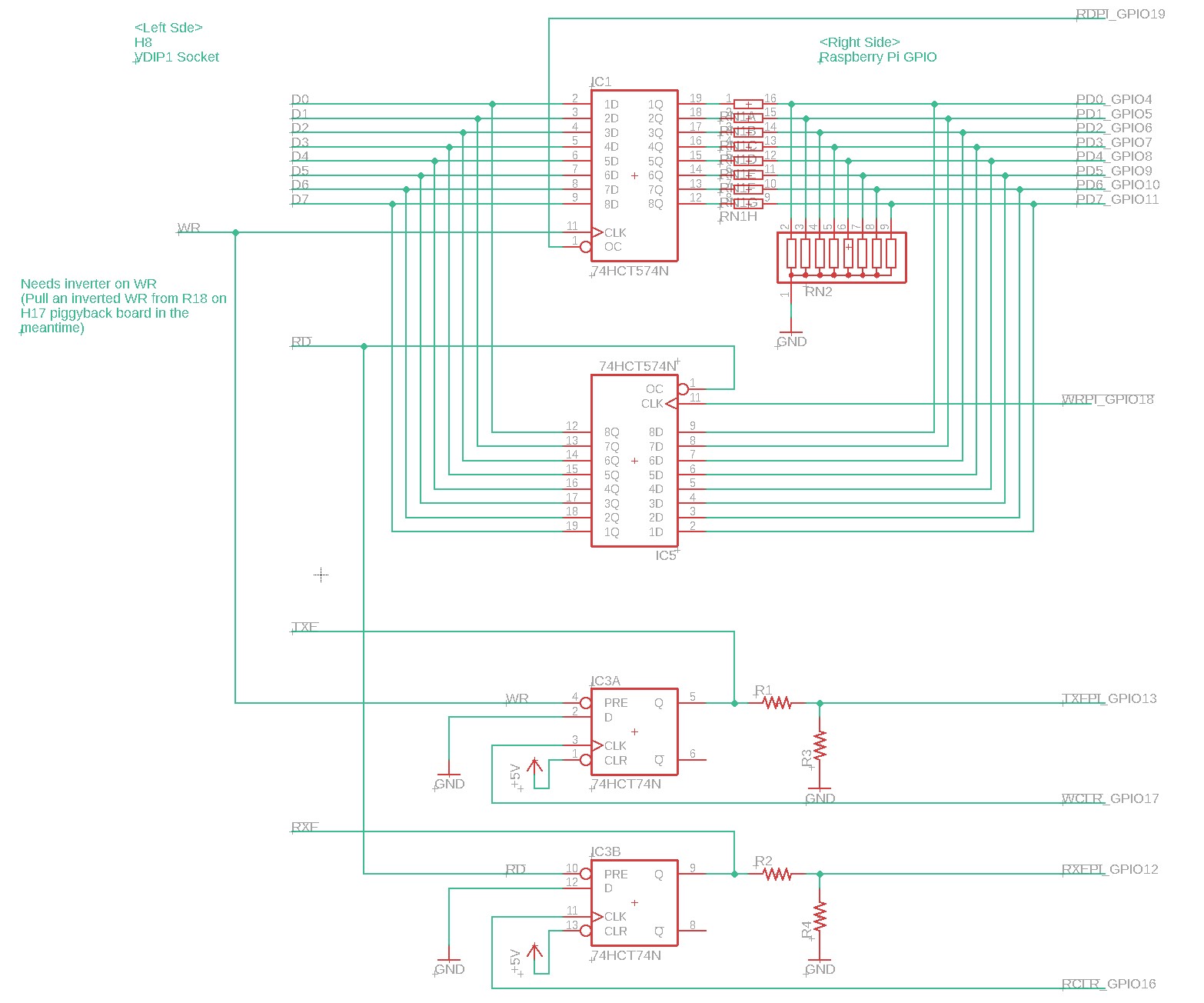
The basic idea is relatively straightforward. Two 74HCT574 latches hold the incoming and outgoing data. When the H8 writes a byte, it goes into the first latch, and the pi can later read it by enabling the latch’s output. When the pi writes a byte, it goes into the second latch, and the H8 can later read it by enabling the latch’s output. In and of itself, this implements a simple 1-byte bidirectional FIFO. Resistor dividers are used to protect the pi from the 5V logic.
However, we also need to implement the handshake. The moment the H8 writes an outgoing byte, TXE must be deasserted. Otherwise, the H8 is going to assume it can write another byte. Similarly, when the H8 reads an incoming byte, RXF must be deasserted. Otherwise the H8 is going to assume another byte is available to be read. This synchronization is done by a 74HCT74 flipflop. The read/write strobes on the H8 use the preset input of the flipflop to set the flipflop state to 1. The pi later clears it by clocking in a 0. We have a simple bidirectional handshake and the pi can take as long as it needs when processing data — the pi in my case is running Raspbian, a general-purpose Linux distribution, and there are no realtime guarantees.
More features and detailed schematics
I decided to take it a lot further than the basic schematic described above. If I have raspberry pi, then why not connect its serial lines to the H8 as well, so the pi can function as a terminal service? and if I’m going to do that, why not add a Propeller-based dumb terminal also?
I’m going to break with tradition and rather than put up jpegs of the schematic, I’ll link to a high-quality pdf.
TODO: Add PDF
Implementation
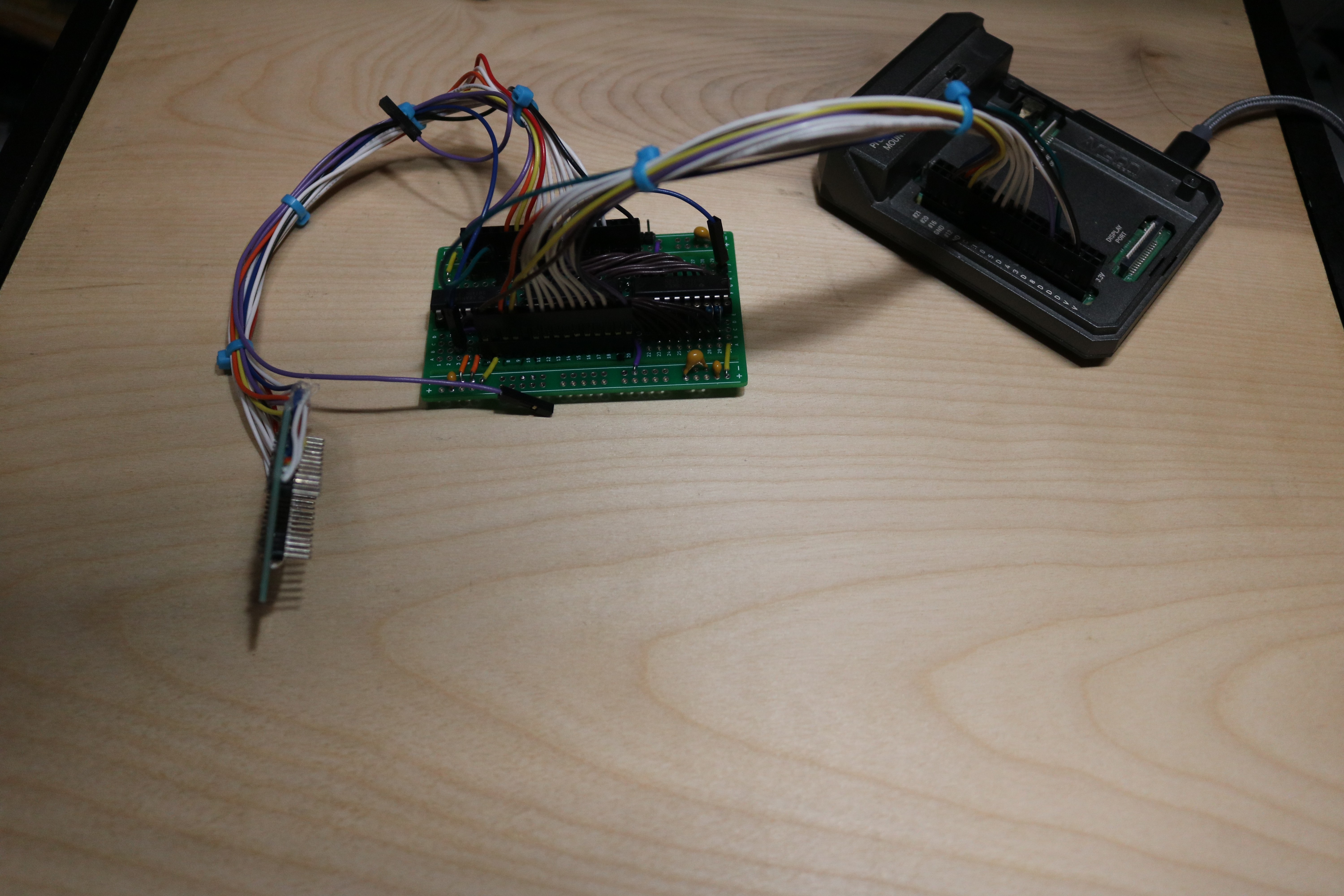
I first implemented the circuit using a breadboard:
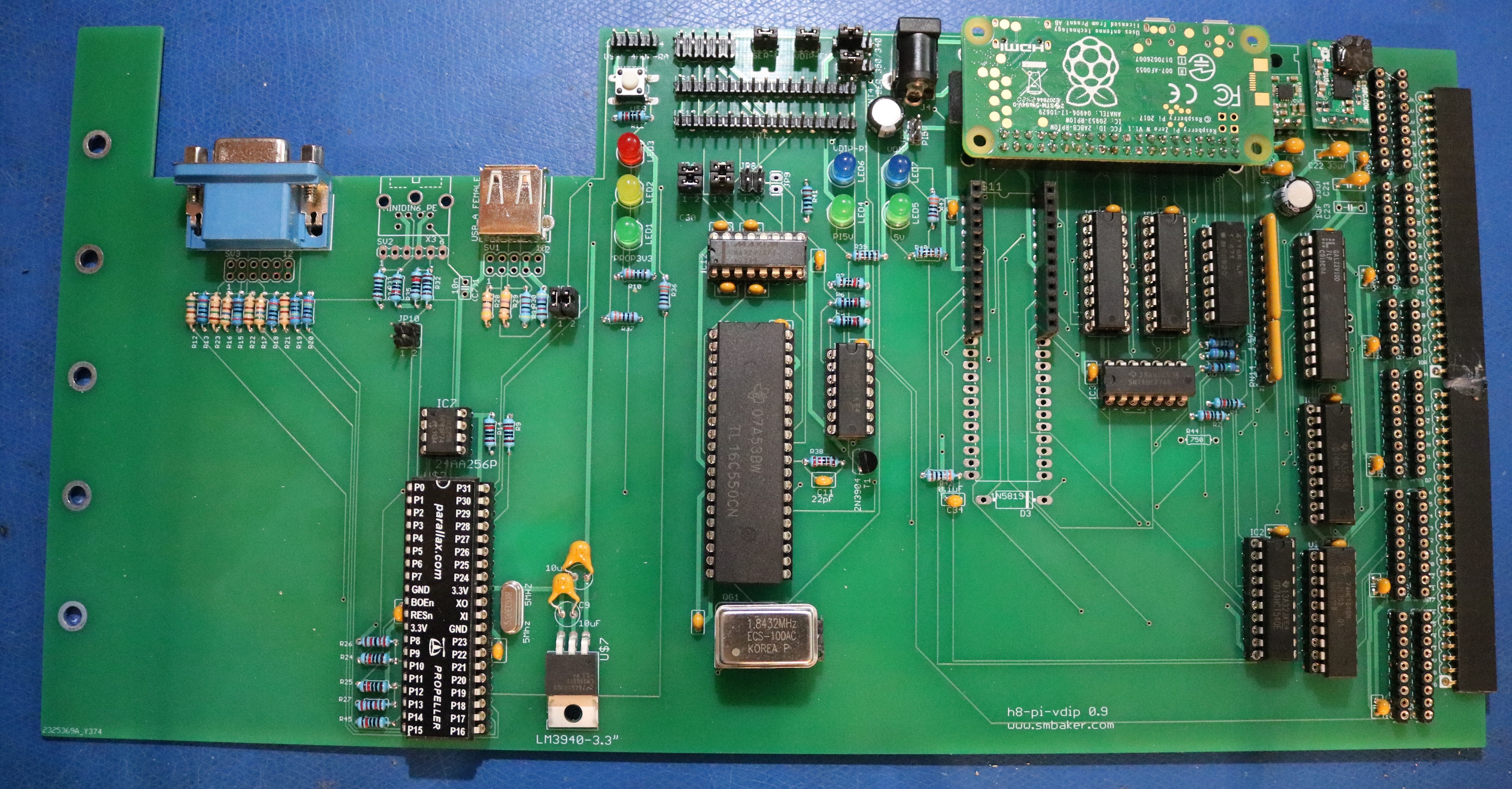
Next, I designed and build a board that I jokingly call the Pinculum board:
Here’s a breakdown of the features:
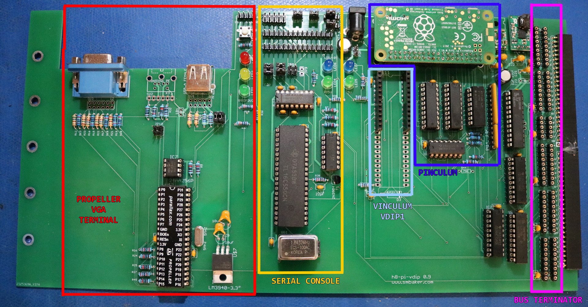
From right-to-left board functions include the following:
Bus Terminator. The Bus Terminator includes two resistor packs per line on the bus. One resistor pack is to ground. The other resistor pack is to +5V. Lines are grouped according to whether they are active-high or active-low. This allows terminators to be selectively placed if desired. For example, all of the active-high bus strobes (IOR, IOW, MR, MW) could be terminated to ground, whereas the active-low data lines (!D0, !D1, …, !D7) could be terminated to +5V. Alternatively, a hybrid technique could be used that pulls the lines toward an intermediate voltage. For example, 330 ohms to +5V, 470 ohms to GND. Be careful of terminating lines that are inputs to the H8 CPU board. For example, pulling one of the INT lines to ground may cause interrupts to be seen by the CPU. Note: Your H8 was not designed to use a bus terminator and does not require bus termination. Nevertheless, if you feel you must terminate the bus, here is your opportunity.
Pinculum. The Pinculum emulates a Vinculum VDIP1 using a Raspberry Pi Zero W or Raspberry Pi Zero 2 W. This may be used with Glenn Roberts’s VDIP utilities to transfer files from the raspberry pi to the H8 computer. The pi may further mount network drives, providing an easy way to move files from a Windows or Linux or Mac desktop machine to the H8, and back. The pi may be powered from the adjacent barrel jack, or may be jumpered to the on-board 5V supply. If using the on-board 5V supply, make sure regulators are capable of sourcing at least 1.5A of power, or the pi could brownout during boot. The pi’s on-board serial port (/dev/ttyS0) may be used to connect to the H8 serial console. If the VDIPEN jumper is removed, the pinculum is disabled.
Vinculum VDIP1. As an alternative to the pi-based Pinculum, a VDIP1 or V2DIP1 could be used in this socket. Populate the Vinculum or Pinculum, but not both simultaneously. If the VDIPEN jumper is removed, then vinculum is disabled.
Serial Console. The 16C550-based serial console may be jumpered to 350/340 and INT3/INT4 depending on preference. 350/INT3 would serve as the primary console port. The serial console connects to two 15-pin headers to mimic the H8-4 connectors, as well as a 2×5 header to use with a modern DB9 cable. The serial console only implements TX, RX, CTS, and RTS. On-board jumpers allow each signal pair to be swapped, in order to simulate a null-modem adapter. If the SEREN jumper is removed, the serial console is disabled.
Propeller VGA Terminal. The VGA terminal uses the Parallax Propeller to provide a VGA dumb terminal onboard. Either a USB Keyboard or a PS2 Keyboard may be used (but not both at the same time; different jumpers and different firmware is required). VGA terminal currently runs the Maccasoft firmware at https://www.maccasoft.com/electronics/vga-serial-terminal/.
Note that all three serial consoles are simultaneously connected to the 16C550. You can use the Pi’s on-board serial port, the 15-pin or 10-pin RS-232 headers, and/or the Propeller VGA terminal at the same time. Output from the H8 will be visible on all three, and input from any of the three serial devices will be directed to the H8. Pressing a key on multiple devices at exactly the same time may yield unpredictable result.
Notes / Problems:
- If your H8 gets stuck on the <SPACE> prompt and using the Propeller VGA Terminal, then please remove R24. It’s next to the propeller chip. The problem is that the H8 deasserts RTS when waiting for SPACE to be pressed. The Propeller VGA Terminal will not transmit while the incoming CTS is deasserted.
Resources:
- Github Repository. Here you can find schematics (coming soon) as well as the files necessary to burn the PLDs, and the python code.