In this blog post I fix a FANUC PPR paper tape punch / reader and use it with both my RC2014 and my Heathkit H8.
Motivation
In a previous video, I repaired an AKI Teletypesetter Keyboard and then modified it to allow tapes to be punched using a raspberry pi and, not part of the video, via serial port as well. That left me in the situation where I could write tapes, but not read them.
A fellow SEBHC member, Mike, mentioned that he had recently got a deal on a Fanuc PPR on eBay, and when I saw what he had accomplished, I decided to try this myself. I found one for $200 but it was (as is usual with my luck), broken. Fortunately, that afforded me the opportunity to diagnose and repair it.
Some paper tape background
Why paper tape? Paper tape saw use in the 19th and 20th centuries as a communications medium and as a storage medium for computers. The tape punches 8 holes per row, and one row per each 0.1″. That’s about 120 bytes per foot. A 17 Kilobyte program, such as the Extended Benton Harbor Basic that I use on my H8 takes about 140 feet of tape. Here’s a shorter tape that contains an H8 Demo program that displays some messages on the H8 Display. This program is only 141 bytes long, including a 32 byte leader and 10 bytes of header and CRC:
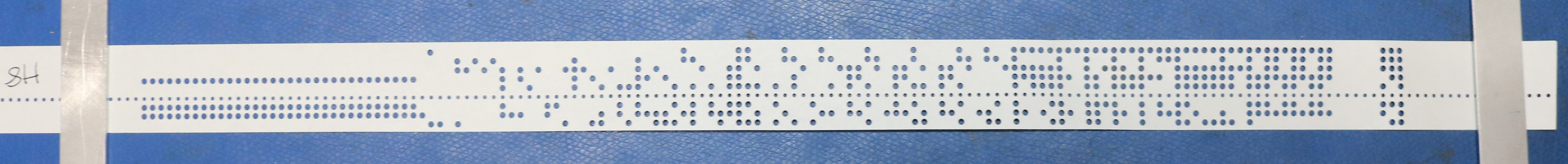
Least significant bit is on the bottom, most significant bit is at the top. You can see there’s a small row of holes that goes the whole length of the tape, between the third and fourth bits. This hole is used by a sprocket to move the tape. Here’s what’s on this tape, from left to right:
- Starting at the left we have 32 bytes each 0x16 that are a sort of leader the H8 writes.
- SOT (0x02)
- Record Type (byte)
- Record Number (byte)
- Record Length (word)
- Program Counter (word)
- Address (word)
- Data (variable length)
- CRC (word)
You could actually manually read the tape if you wanted to.
Tapes are typically read using a photo sensor of some sort. These days we’d use LEDs and phototransistors. Older equipment might actually use incandescent bulbs. I’m not sure what the PPR uses. Punching a tape is inherently an electromechanical process. Some punches will use solenoids to directly drive punches, but many industrial or commercial quality punches seem to use a motor that drives a cam, together with solenoids that cause the cam to selectively engage the punches. Accurate timing is important, and the punches are designed to punch at that 0.1″ interval.
Most punches will either be serial or parallel interfaces. The Heathkit H10 punch, for example, had an 8-bit parallel interface (which was actually driven on the H8’s H8-2 board by two UARTs hooked back-to-back, to make the parallel interface “look like” a serial interface from a program perspective). Slightly more modern equipment like the FANUC PPR will typically have a serial interface with some buffering capability. Flow control is important as the typical punch may not be able to keep up with even slow baud rates like 1200 baud.
Several different forms of tapes may be found in the wild, including:
- Oiled paper. Perhaps the oldest, the paper was coated by some kind of oil, as either a protectant or a lubrican.
- Non-oiled paper. Just plain ordinary paper without the oil.
- Mylar. Used by the CNC folks (machinists / metal workers) to operate their computer-controlled milling machines and lathes. Vastly more durable than paper, but punched and read in exactly the same manner.
Different equipment might have different number of bits
- 8-bit. Used by most computer or CNC equipment. Sometimes encoded as 7-bit with one bit of parity.
- 6-bit. Often used by typesetters. 6-bits is enough to encode the 26 letters, 10 numbers, and a plethora of symbols and a shift character.
- 5-bit. Not sure, but you can find tapes of this width. Possibly used to encode 4-bit numbers with a 5th bit for parity.
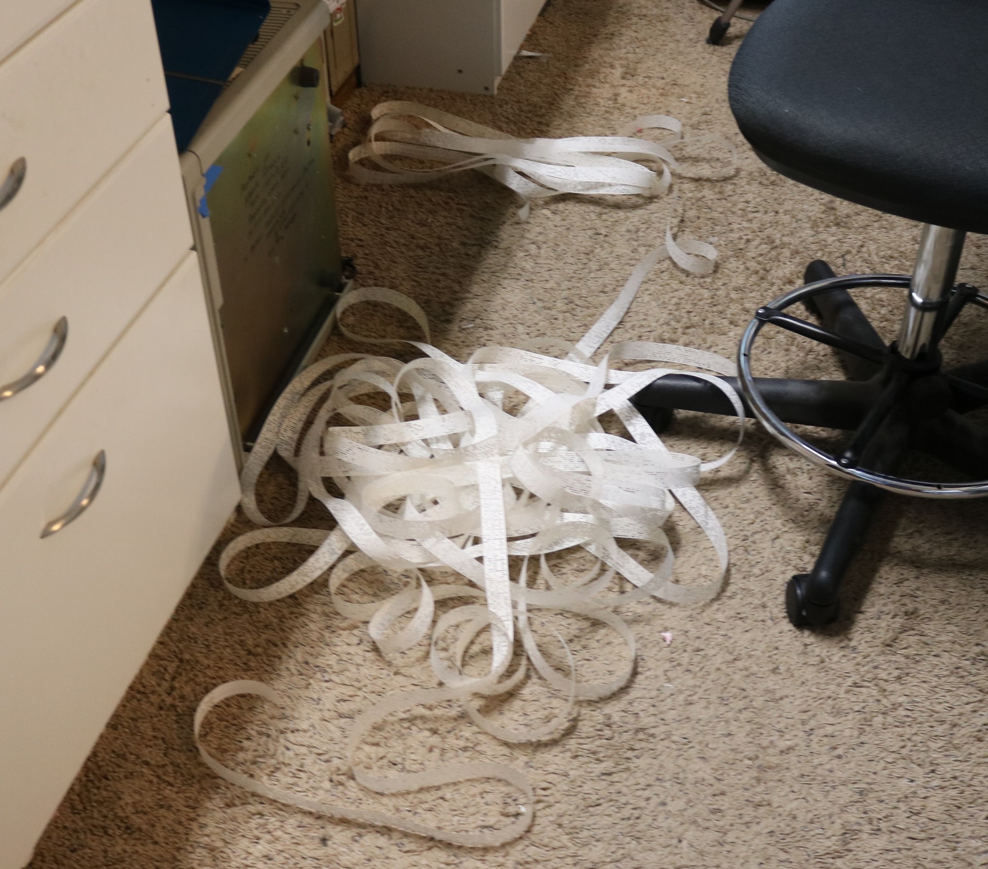
How long of a program can you save to tape? Pretty much as long as you’re willing to deal with. Here’s Extended Benton Harbor Basic v2, all over the office floor:
The FANUC PPR
The FANUC PPR is a 3-in-1 device.
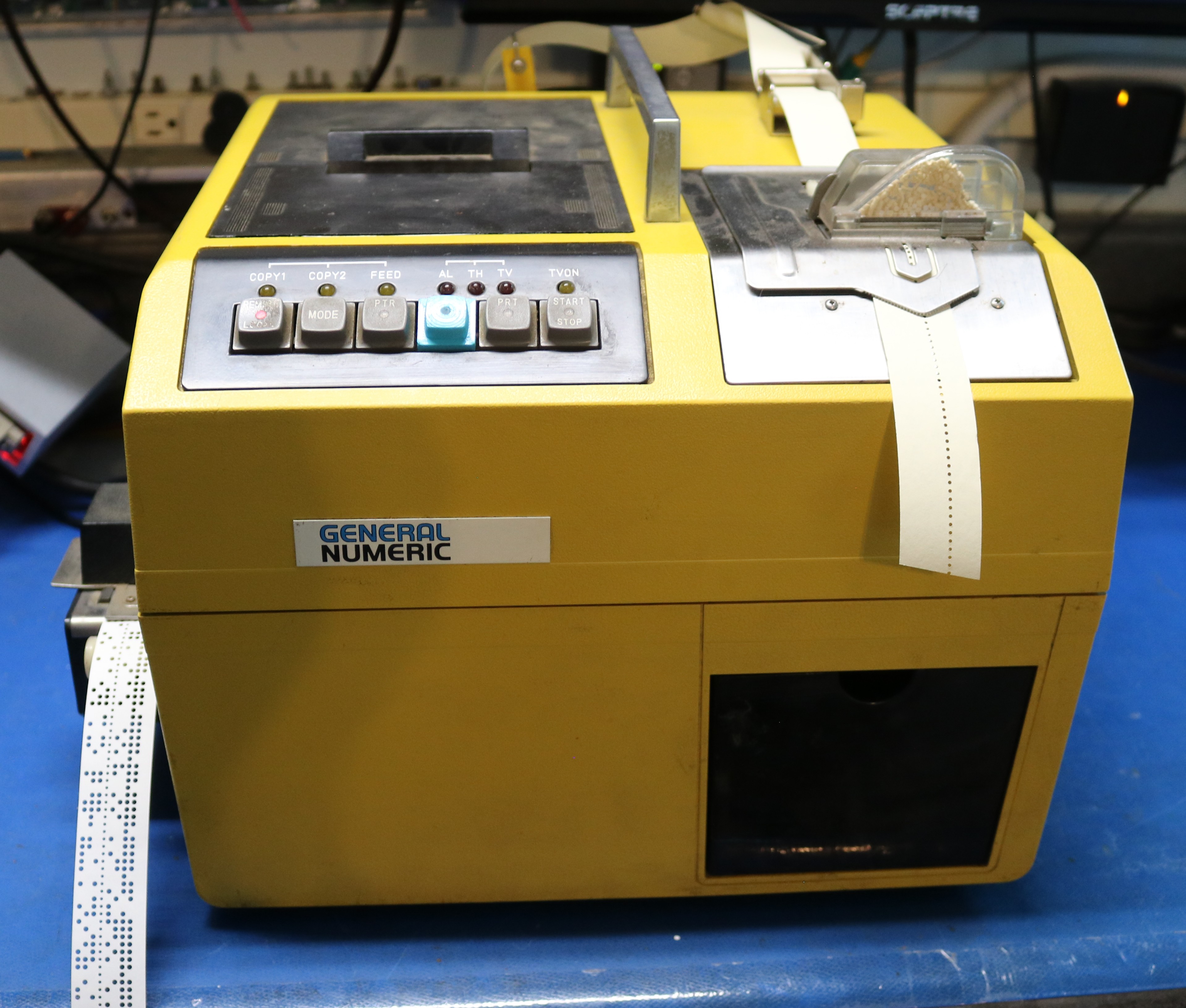
It has all of these functions:
- Paper tape punch. It can punch paper or mylar tapes. This includes punching the index holes that run down the middle of the tape.
- Paper tape reader. It can read paper or mylar tapes. It can do so at a fairly high speed (up to 4800 baud) and will spew tape all over the floor as it does so.
- Printer. It contains a built in cash register style printer that uses 69mm (just shy of 2.75″) cash register paper together with an old timey ink ribbon. It can print 7-bit even parity ASCII or EIA-244/RS-244. This is for humans to read.
- Copier. The PPR will read from the reader and output to either the punch or the printer if you want to copy a tape.
Repair
When I received my PPR from the eBay seller, it didn’t work. That’s alright, it was listed as “parts/repair”. The symptom was that when powered on, all LEDs would stay lit and the keypad was nonresponsive. The manual troubleshoots this as “logic board failure” and says to replace the logic board. Well, I’m gonna fix the logic board. Here’s the original logic board:
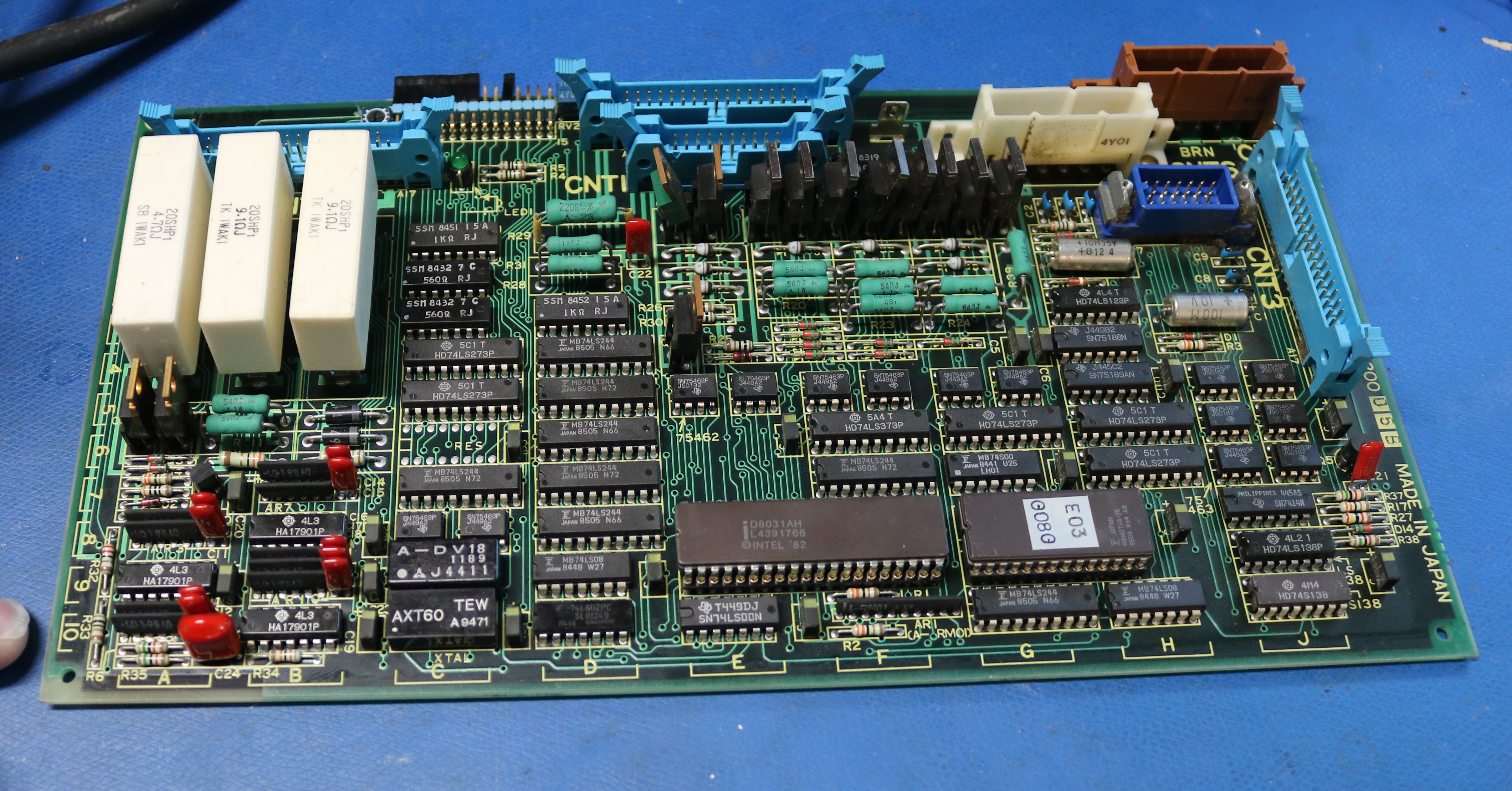
The 40-pin IC is a P8051AH microprocessor/microcontroller. This is the variant of the 8031/8051 that does not feature built in program memory, and sitting next to the 8051 is a 2764 EPROM that contains the firmware for the PPR. To diagnose I got out my logic analyzer and confirmed:
- The CPU was not fetching instructions from the ROM.
- The RESET signal appeared to be working as expected.
- The Clock was not oscillating.
No clock? That’s a problem, so I took a close look at these two custom ICs:
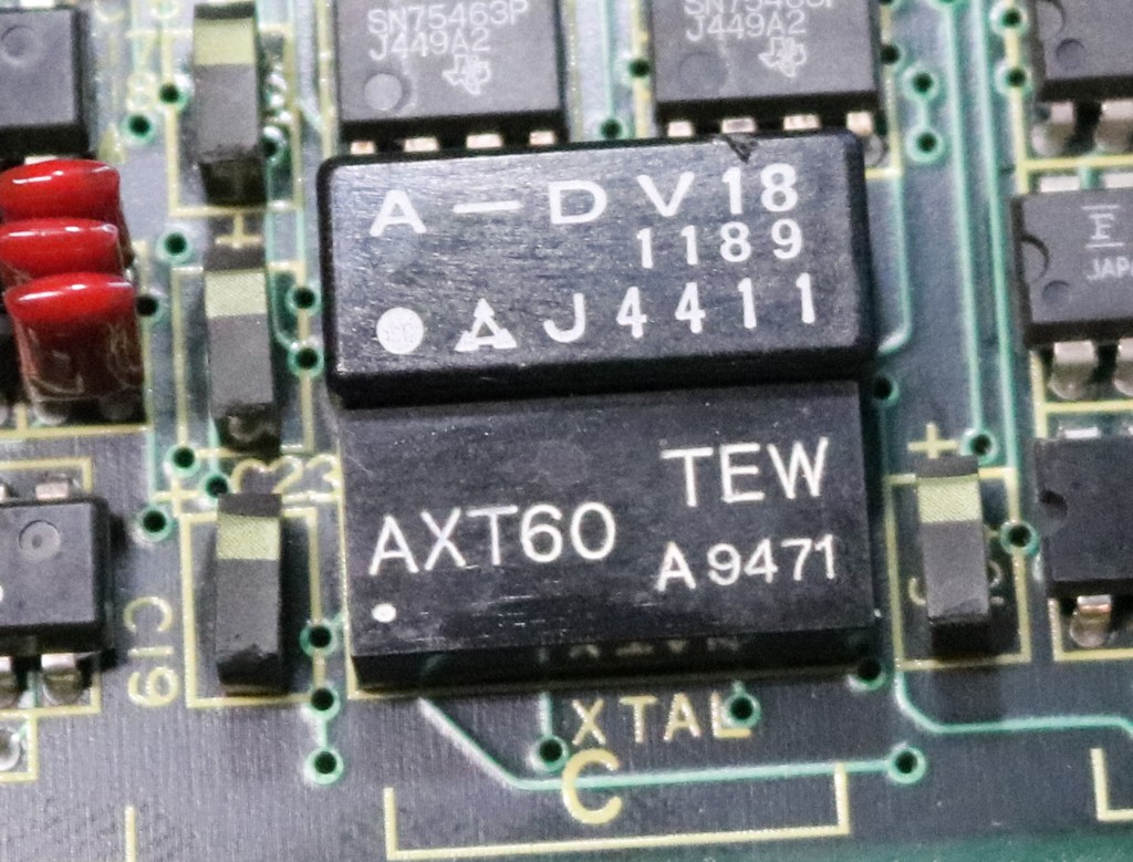
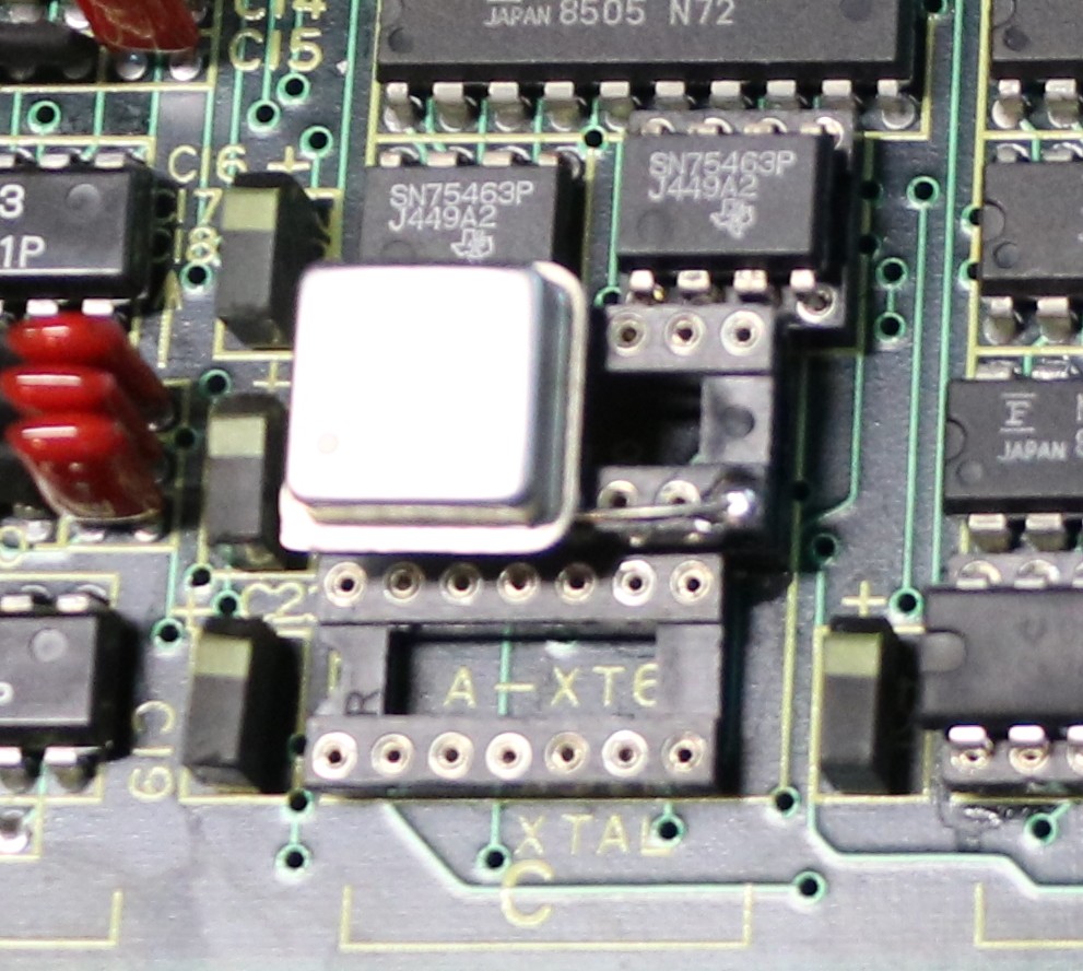
These are both custom ICs, components potted in goo. They are not available anywhere unless you want to pay hundreds of dollars from a scrapper. The lower one, marked XTAL, I tested and found it to be a quartz crystal that resonated at 11.0592 MHz. Don’t let the 14-pin size fool you, only two pins of it are connected. Its neighbor to the north is what I expect was damaged, and is likely all the rest of the guts that make up a crystal oscillator. It was connected to 5V, GND, two pins to XTAL, and one pin to the 8051’s CLK input. I replaced this with a modern 11.0592 MHz oscillator:
Okay, that was enough to get it clocking and to get it fetching, but I still had stuck LEDs on the logic board and the buttons were as responsive as an inert lump of coal. Something else was wrong, and I tracked it down to two input buffers being active on the data bus at the same time — one buffer for the ROM and one buffer for the input peripherals (tape reader, buttons, etc). The problem was with the peripheral buffer, and by reversing the schematic I found that a pullup to some logic had been pulled down to -1V. The problem was traced here:
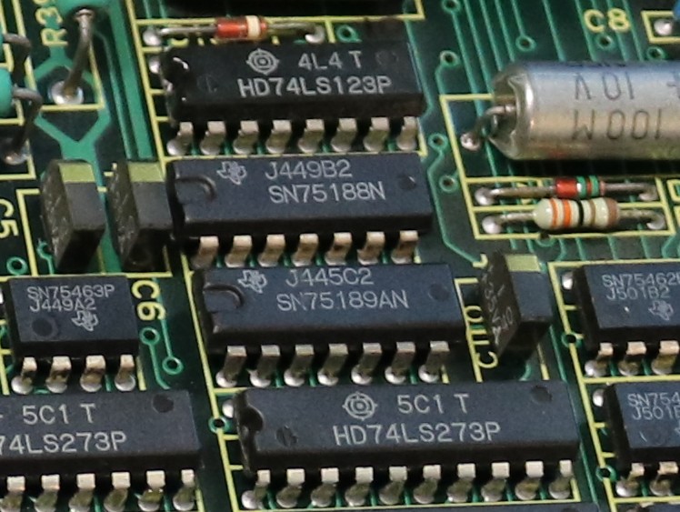
The 75188 is a serial output driver and takes as its supply voltages +12V and -12V. It was leaking some of that -12V out onto its input pins, and pulling the logic board’s common pullup down to -1V. That input should have been at +5V not -1V. I suspect what happened was that someone plugged the DB25 serial cable into either a faulty piece of equipment, or something that was not a serial port, and fried the 75188. I desoldered and replaced the 75188. The board worked.
mostly…
Occasionally the board would spontaneously reset. I took a look at the reset circuit:
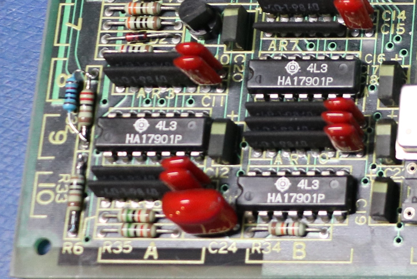
R32 and R33 form a voltage divider that divides the +5V supply down to approximately 1.5V. Nearby is a comparitor that compares this to a 1.5V reference and resets the CPU if it believes the input voltage is too low. It wasn’t really that low, and I suspect some component drift may have been to blame. As you can see I soldered the little blue resistor in parallel with the upper half of the divider, pulling the signal a little higher and resolving the false triggers on the reset circuit.
After this, the board worked flawlessly.
Interfacing to RC2014
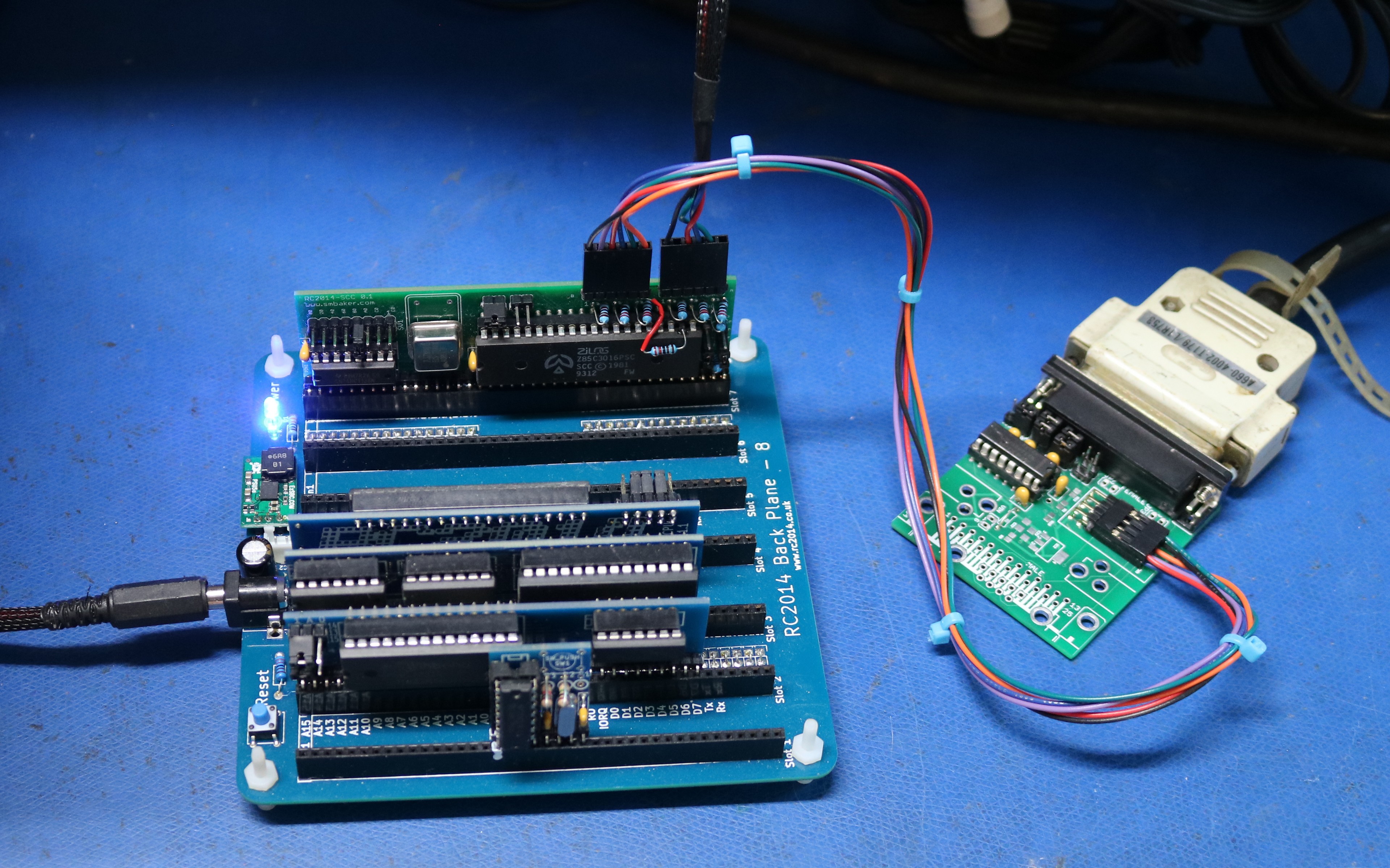
If you recall my “Bubble Basic” project, I designed a two-port SCC serial board for the RC2014. Part of the reason for that two-port board was that I was planning these paper tape projects. Port0 I use for the console, and port1 I connect to the PPR. I added the following commands to RC2014 BASIC:
- LLIST – list program to printer
- LPRINT – print string to printer
- LBAUD – set printer baud rate
- TSAVE – save program to tape
- TLOAD – load program to tape
The TSAVE command writes a 32-byte leader of 0x16 followed by the bytes “T”, “A”, “P”, “E” and a length and a checksum and then the data. That’s my own private save format for this project. The TLOAD command simply reads until it encounters “T”, “A”, “P”, “E”, then it parses the length and CRC and loads the program.
Interfacing to Heathkit H8
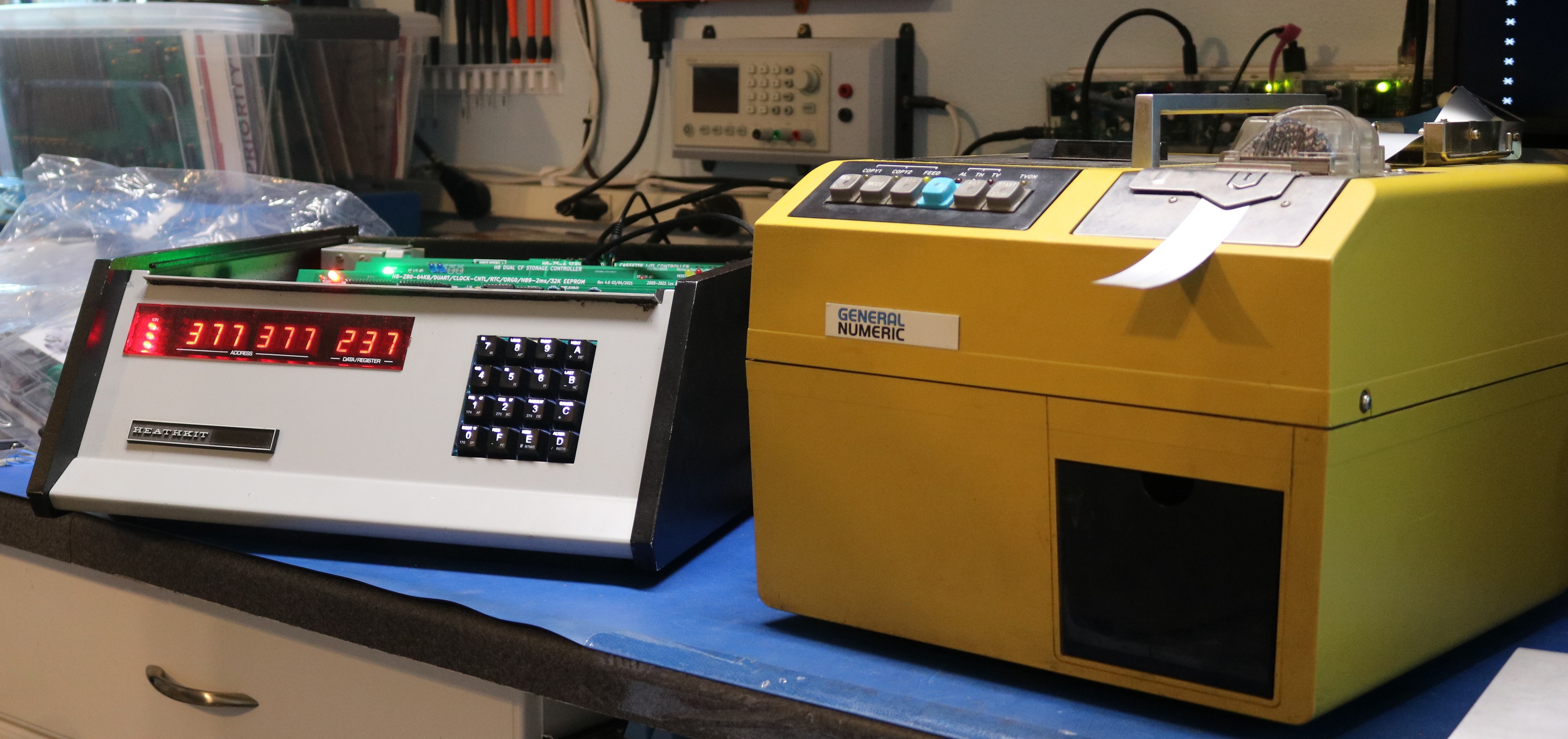
This was easier. Norberto Collado already created a magnetic tape board for the H8, and his tape board has provisions for outputting to a serial port. Norberto did this with the intention that a laptop or other modern computer could be used in lieu of the magnetic tape. His board works with the FANUC’s serial connection. Almost.
There was one issue with Benton Harbor Basic — when loading or saving program, Benton Harbor Basic expects to see transitions on the RTS pin and it will actually wait for this to happen. The PPR has a generous (about 32 bytes or so) and doesn’t cause this transition at the time BHB expects to see it, and BHB would hang while saving programs. I fixed this by simply NOPing out that wait — perhaps it’s necessary for some reason when using magnetic tape, but it’s certainly not necessary when using a buffered paper tape.
In search of an H10
Heathkit made a paper tape punch / reader for the H8 called the H10. I wouldn’t mind one, though I’m probably too cheap to pay what it’s worth. One can dream…
Watching a DDP516’s 1000cps reader operate is entertaining, with the tape is fly horizontally for a couple of metres, and landing in a big “laundry basket”. Just keep your fingers away from the moving tape’s edge!
5-channel paper tape had multiple encodings. ASCII was a godsend when it arrived!
Letters and symbols were “multiplexed” onto 32 symbols using “letter shift” and “figure shift” keys/codes. That abomination has been reinvented for tablets; youngsters forget history and condemn users with their abomination.
I have one of theses I’m trying to use with my altair but not having good luck inthink its because the funuc sends 7bit and the altair is 8 any ideas I’m looking for anything that might get me closer.