In this post, I take my H8-8008 board design and turn it into a single-board computer based on the 8008 CPU.
Purpose
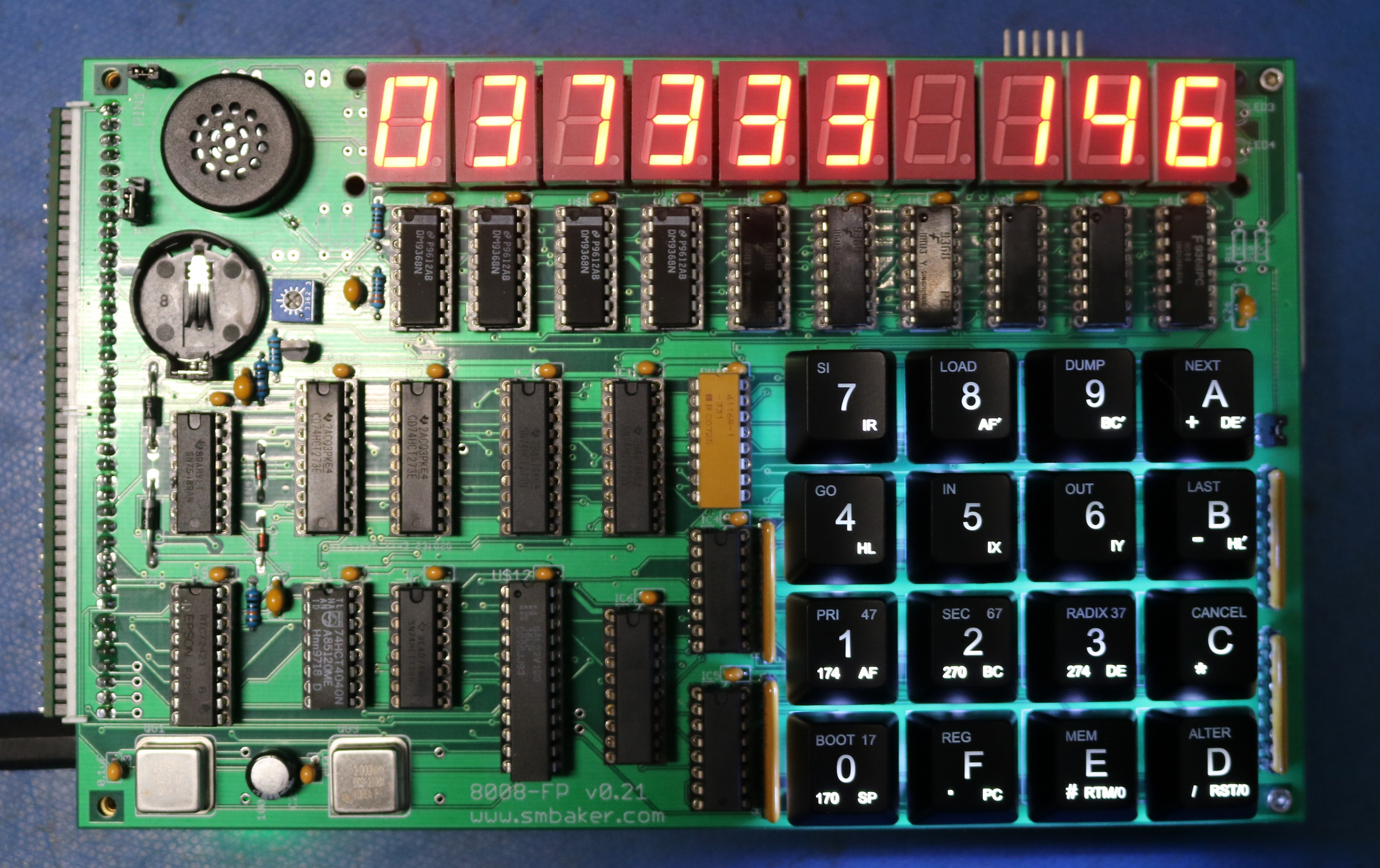
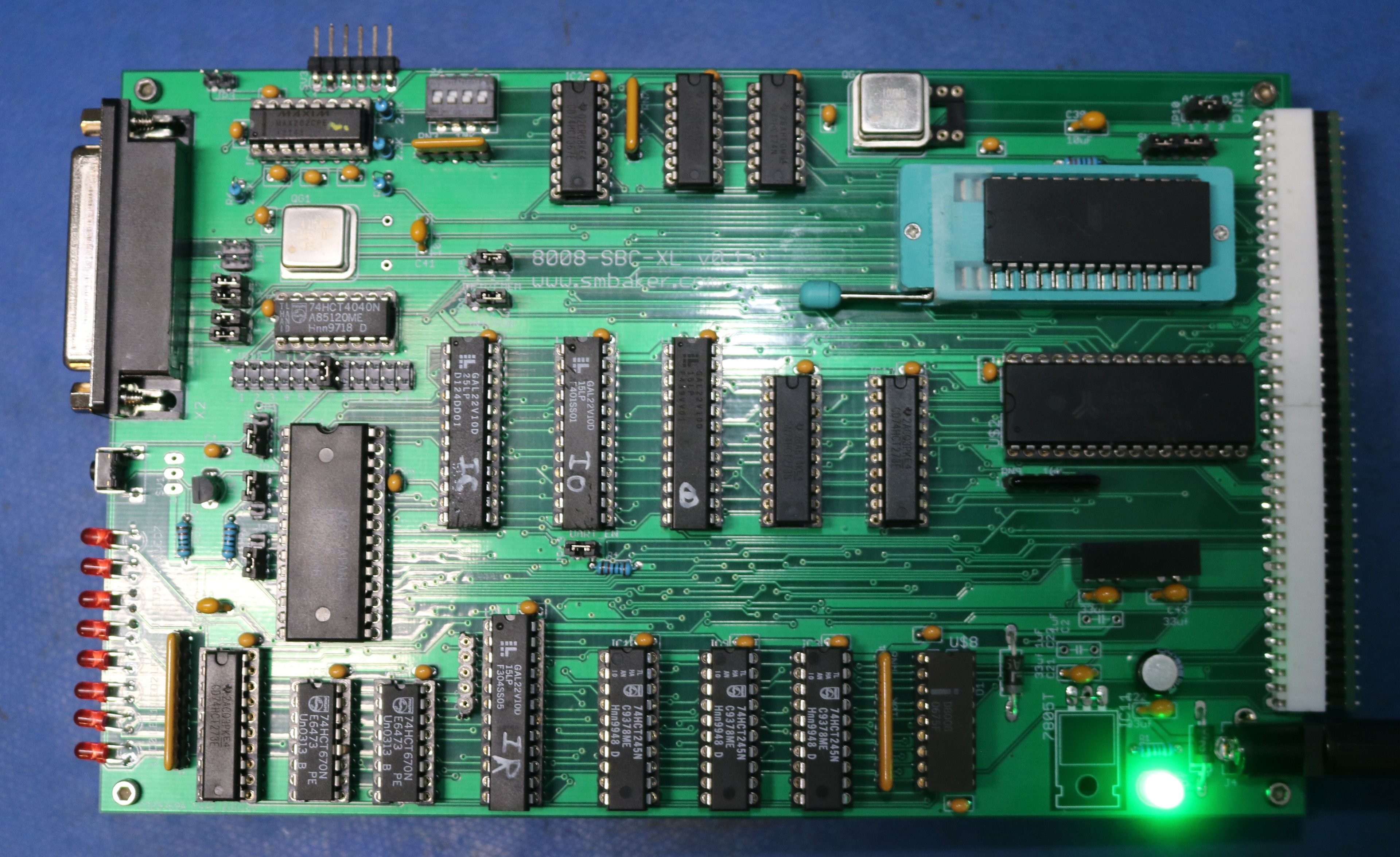
A few months ago, I designed a CPU board for the H8 Computer that used the Intel 8008 CPU. I decided to take that design and translate it back into a single board computer, with an optional display board. At the same time, I made a few improvements, for example increasing the banked memory support from 32KB RAM/ROM to 128KB RAM/ROM. Now, we don’t really need all that RAM, but the ROM is useful to store additional programs that may be bank switched in. Here are a couple pictures of the completed computer with its display board:
Overall Architecture
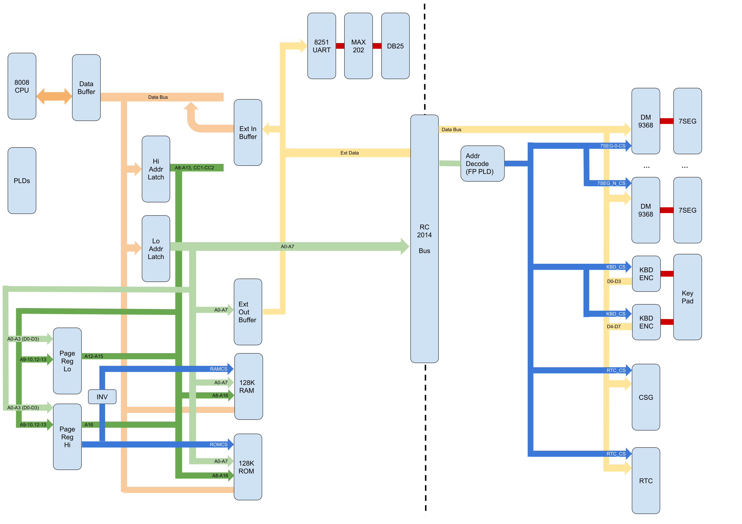
Here’s a picture I drew up in google drawings to show how the various bits fit together:
Design – CPU Board
The 8008 CPU has a triplexed bus, meaning that there’s an 8-bit bus that is shared between the data bus, low address bus (A0-A7), and high address bus (A8-A13, CC1-CC2). The data buffer buffers IO in and out of the CPU, and a pair of latches handle latching the address bits and control bits at the appropriate time. There’s two additional buffers used as input and output buffers for the external (“RC2014”) bus connector.
An idiosyncrasy of the 8008 is that a Port OUT instruction does not place its data on the data bus, but instead outputs it onto the address bus. Well, it’s a triplexed bus, so it’s really all the same bus… But the outgoing bits go out in the address phase not the data phase, so they end up latched into the Lo Addr Latch as A0-A7. This complicated the interface for the RC2014 bus connector slightly which is why I have two buffers there instead of a single bidirectional buffer.
Memory is paged by use of a couple 74HCT670 4×4 register files, a staple of the modern retro-computer movement. These allow us to take the upper two address bits (A12, A13) and map them to 5 address bits (A12,A13,A14,A15,A16) and a ROMCS signal (which can be inverted to create a RAMCS signal). This gives us our 128 KB of address space and two memory devices (ROM and RAM). Memory mapping is disabled on boot up, so that all memory is read from ROM, regardless of bank. The first thing the ROM program does is to enable memory mapping, so that RAM can be used.
Several Programmable Logic Devices (PLDs) are used to handle bus signals, io addressing, interrupt support, etc. The PLDs used are GAL22V10D. Each one replaces about a half-dozen discrete logic chips, vastly reducing board size and component count. There’s nothing magic in them — they’re just plain ordinary logic comprised of your typical ANDs and ORs and such.
For more information about the CPU board, I suggest you start with my prior blog post on the H8-8008 CPU board, since I covered most of it there.
Design – Display Board
The display board is connected to the RC2014 bus connector. The display board has one GAL22V10D PLD that handles all of the IO addressing, selecting various onboard devices as necessary. These include:
- DM9368N 7-segment display drivers and their associated 7-segment displays. Each one of these takes 4-bits and maps them to a hex character 0-F. The DM9368 also has a blanking input to turn off the display and a latch pin to latch the current 4-bit value. The DM9368N does not handle the decimal point on the display, so we’ll handle that separately. There are 10 of these drivers and 10 displays, each being 4 bit, accounting for 5 bytes of IO space and 5 write-only IO ports.
- Latches to hold the Blanking Inputs and Decimal Points for the displays. Each 8-bit latch can hold even blanking inputs or decimal points for 8 displays, so we need about two-and-a-half latches to take care of our 10 displays.
- 74LS148N priority encoders and a 74HCT245N buffer to support a 16-digit hexadecimal keypad. 8 bits encodes the 16 keypresses.
- SN76489 CSG “Complex Sound Generator”. This is the sound chip popularized by the Tandy 1000. It supports 3 voices of musical notes, and 1 voice of noise generation. A single 8-bit port is sufficient to program it. Although it does have a CS input, it also requires wait states in order to load its data. So I stuck a latch in front of it and added a bit of logic to simulate a wait state.
- RTC72421 Real Time Clock. The RTC has an associated battery backup. It needs two IO ports, one to load an address of which register we want to read, and the other to read or write the register contents. All registers are 4-bits wide, and this is enough to transfer a single BCD-encoded digit. So we read the 1-second, 10-second as two separate reads.
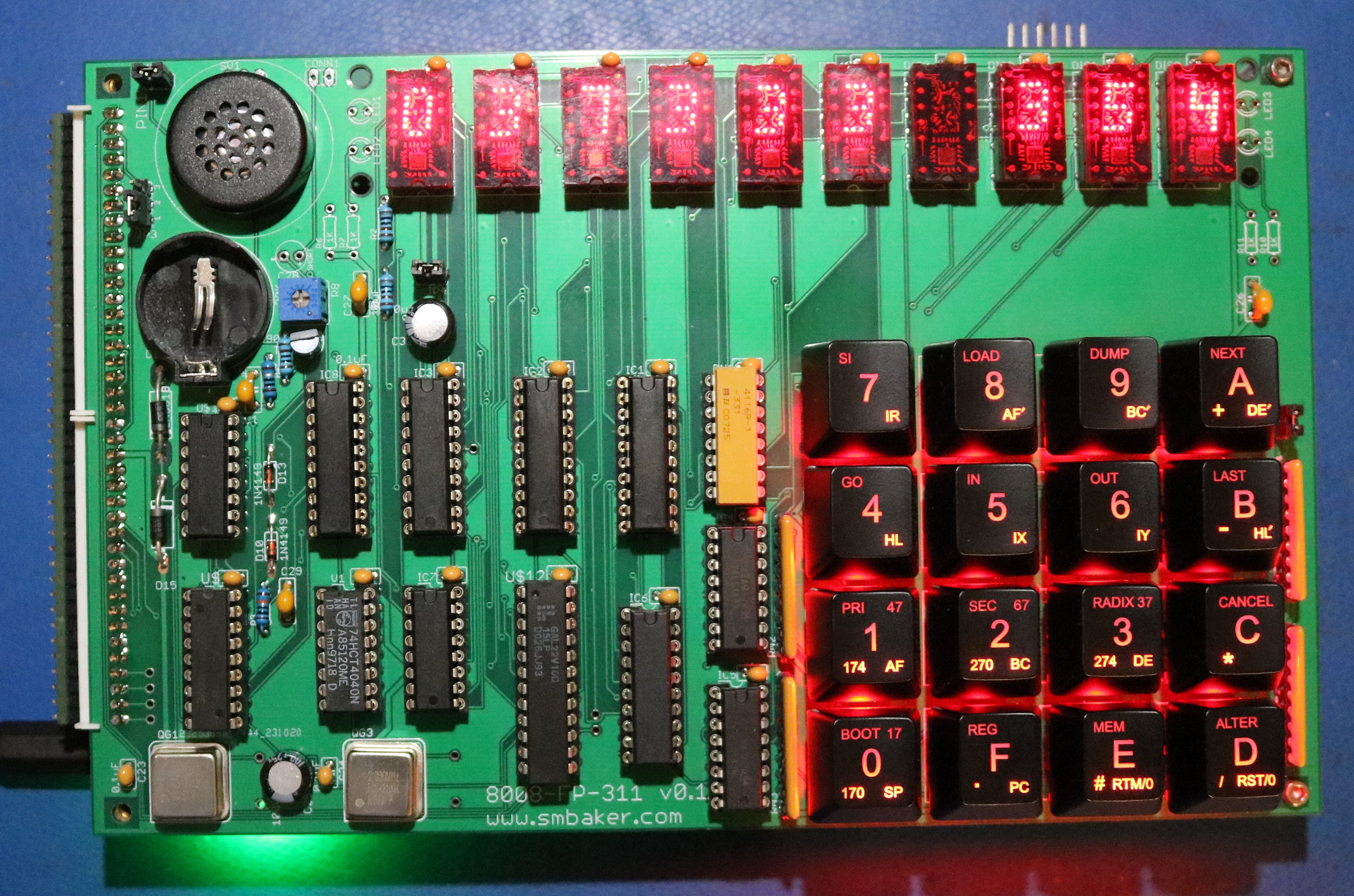
TIL311 Display Board
The DM9368 Drivers in the default display board can be a little hard to find and you have to be careful of counterfeits. I did produce a variant that uses TIL311 displays. The digits are a little bit smaller, they’re also hard to find (a guy in the UK sells them) and they’re also expensive, but so far it hasn’t been a problem with counterfeits.
Software
The board supports the following:
- The same 8008 Monitor that I used on the H8-8008 board, which is based on a monitor by Jim Loos. There’s a slightly different build of the monitor to support the display board, since the display board is different from the H8’s display board.
- Scelbi Basic
- 8008-Forth. My port of Jonesforth for the 8008. Forth is a cool programming language. I like it better than Basic.
- Galaxy. A Star Trek clone written in 8008 assembly
Resources
- Github Repository containing PLD files, schematics, gerbers, and other resources.
- Jim Loos’s 8008 SBC. It’s what I used as a reference while creating the H8-8008 board, which sort of makes it the grandfather to this SBC.
- JonesForth. You can learn how to program in Forth and learn how to write a Forth interpreter/compiler at the very same time. How cool is that?
- 8008-Forth. Source code for my 8008 port/rewrite of Jonesforth.
An impressive project! I tried to build a Mark-8 back in the 1970s, but failed (I was too young and inexperienced). But I do have a more recent design by Len Bayles. It’s almost all vintage parts except for two PALS.
Have you looked into VTL (Very Tiny Language)? As I recall, it was a BASIC-like language that ran on an 8008 in less than 1K of memory.
What is this Star Trek game called Galaxy? Never heard of it nor can I find good info about it.
This looks like a cool project! Have you thought about making a SBC using an old 8088 CPU (I kind of miss those old days! LOL)?
Used 8008 for telecom application that required 256K of memory. Added a multi-register chip to implement what we now call a memory management function.
Intel application engineer was very interested. Wish I’d patented.
You can find the details on it here — https://bytecollector.com/archive/mark_8/My_Mark-8_Info/Scelbi_Computer_Consulting/Galaxy_Game/Galaxy_Game_8008-8080.PDF. I think it was actually distributed in hardcopy form, and you’d type it in. As to why it’s called Galaxy rather than Star Trek, perhaps due to copyright / trademark issues?
Have not looked into VTL, but sounds interesting!
I’ve built a board based on Jim Loos’ 8008 design, and I have added your FORTH to the monitor ROM that he wrote. Incredibly, both my modifications to the monitor (minor) and your code (major) worked first crack, although I only used the upper 8K of the FORTH.BIN file for addition to the modified monitor/SCELBAL UVEPROM image – so, monitor + SCELBAL + FORTH = 24K of 32K.
Learning, Forth, in particular, THAT Forth, might be a challenge for me…
There were very few high level languages ever written for the 8008, and even fewer still existing.
Wow, these 8008 SBCs are very cool! I definitely need to build one or two of them. I also have an H8 that I’m in the process of restoring, and your H8 8008 is very tempting.
I was curious on a couple things:
1) Where did you get/make the keypads on the two display SBCs?
2) Can you share the source you used for the SN76489 and RTC72421 ICs?
I was thinking of trying UTSource. I haven’t every used them. Going eBay/China is a crap shoot, and my guess is I’ll get fakes.
Just thought I’d ask how you got yours, and if you were happy with the source you used?
Thanks for everything you do for the community. I’ve built several of your project, and I have to thank you for sharing.
Hi! I had some boards made and am building one of these (with the TIL311 front panel), but I’m unsure about the values for RN2 and R3 (on the main board). Neither of them seems to be specified by value in the BoM, silk screen, nor schematics. I’m guessing that R3 is 2.2Kohms, judging from where it is, but I see that, in your photo, RN2 is populated with an empty SIL socket, and, in your video, there’s a resistor network in that SIL socket. It looks like a pull-up resistor network, so I assume that it needs to be populated with something. Is it 1Kohms? Was a socket used so that it could be removed for certain purposes, or just to experiment with values? Thanks!