In this video, I follow a Hackaday.io post that describes a DIY Jupiter Ace project, then I design three of my own modules to go with it.
Motivation
It all started when I acquired a speech synthesizer for the Timex Sinclair and set off to build myself a Timex Sinclair clone. Along the way I stumbled onto the Jupiter Ace, and being a FORTH-based computer that was a commercial failure, I just couldn’t resist the diversion of building one of these unique computers! That’s often how these journeys go — you start down one path and encounter something interesting along the way.
The Jupiter Ace was a British computer created in 1982 by the Jupiter Cantab company. Its contemporaries at the time would have been small Z80-based home computers such as the ZX80, ZX81, ZX Spectrum, etc. All of these other computers ran BASIC as their embedded programming language, but Jupiter Cantab thought they’d try to do something different and instead of implementing BASIC, they chose FORTH. If you’ve read some of my other posts lately, you can see that I’ve been on a bit of a FORTH kick, implementing it for the 8008 and also porting public FORTH implementations to the Olivetti M20 and to my own H8-80186 board. I’ll leave other references to extoll the virtues of the FORTH language, its structure, and its efficiency. Unfortunately for Jupiter Cantab, the FORTH programming language, while being a really interesting move technologically for a small computer, was not as well received in the marketplace. According to Wikipedia, only about 5000 Jupiter Aces were sold.
A Hackaday.Io project by Cees Meijer, titled “Recreating the Jupiter Ace” has Kicad schematics and layout for a Jupiter Ace clone. It makes a few small changes, such as substituting the more readily available 6116 RAM instead of the more obscure 2114 RAM chips. Prior work includes schematics drawn up by Grant Searle.
Re-Recreating the Jupiter Ace
It’s always fun to grab some project from the Internet and see if you can reproduce it. From Cees’s page, I downloaded his Kicad files, loaded them into Kicad 6.0, ran a gerber job to produce the Gerbers, and sent them off to JLCPCB for PCB production. Acquiring the components was not too difficult, as I already had almost everything. The one noteworthy item I was missing was the 6116 RAM chips. I found a vendor on eBay and ordered them.
Building the Jupiter Ace was relatively easy and I did so with minimal modifications. For example, I chose to use a barrel jack for my +5V supply, and a Pololu switcher instead of a 7805 regulator. But as far as I can recall, the rest of it was the same. I did substitute a BS170 for the 2N2369 transistor, and this led to my first issue — I didn’t realize you had to rotate the BS170 180 degrees relative to the symbol on the pcboard. Keep this in mind when doing transistor substitutions. Once I resolved this, the Jupiter Ace was clocking and producing video output, or at least try to.
The white screen
On my first boot, I was presented with an all white screen.
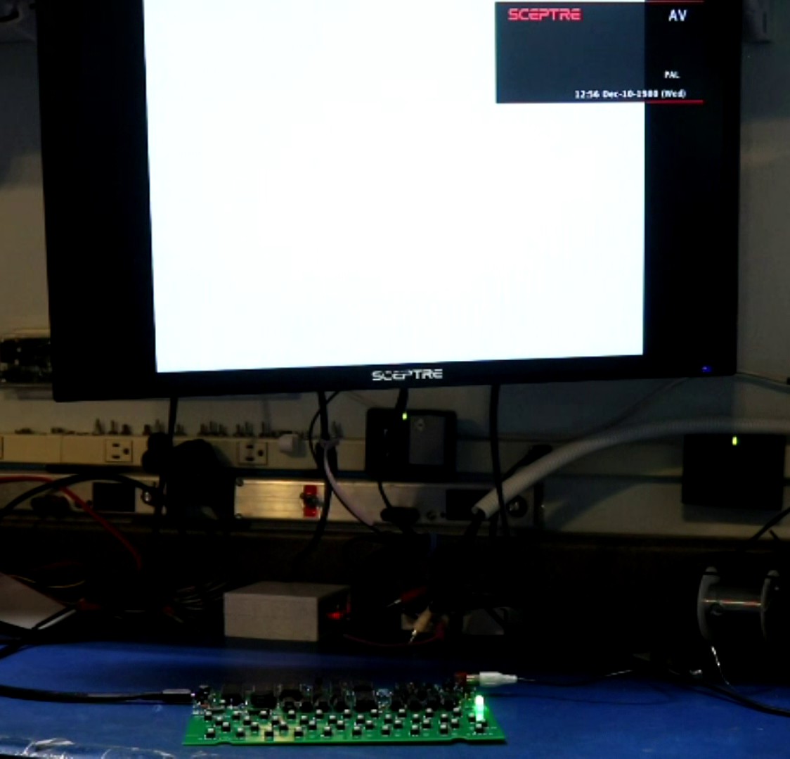
While trying to diagnose this, I hit enter several times, then plugged and unplugged the composite video to my monitor and I saw text! It was bright white text on a dark white background, but it was text nonetheless and proved the computer was working.
I ended up pulling the 555 timer IC from the board, and the video cleared right up and appeared as it should. I’m still trying to understand why it doesn’t work right with the 555 timer installed. Talking it over with Cees, he confirmed my suspicion that this was to improve the backporch signal. It worked fine on his monitor, but it did not work on mine. I need to spend some time to research more about composite video signals, so I can understand.
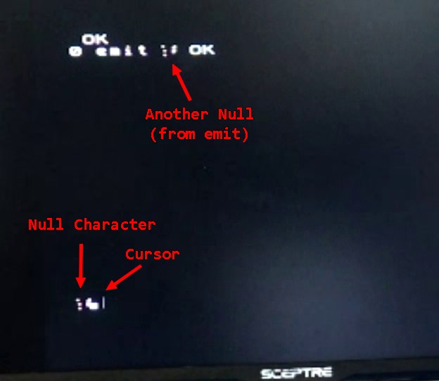
What’s that weird character next to the prompt?
The next thing I noticed was that every time I repowered the computer, I would get a strange symbol to the left of the prompt. The symbol was different every time. It turns out that the Jupiter Ace stores a NULL (i.e. byte 0x00) in this particular location of video memory. The character set RAM for NULL was being corrupted for some reason, and rather than displaying the NULL as blank, random garbage was displayed. This wasn’t a big deal, so I moved on.
But then the problem came back to me a little later when I tried to load some Jupiter Ace games. The first thing most Jupiter Ace games do is to redefine many characters in the character set RAM, and this time the problem was not just confined to the NULL character. Many different characters were being corrupted, including such things as the space character. Games were pretty much unplayable.
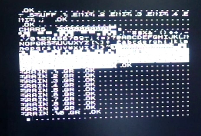
I tracked this down to the timing of the signals to the character set RAM. Looking at the schematic, I could tell that the !WR signal could go low before the address bits had arrived to the character set RAM. This would only happen if the program tried to write the character set RAM while the screen is refreshing. The Ace has two ways to write character set RAM — one way pauses and waits for vertical retrace and the other way writes immediate (causing visual glitches). It’s the former that wasn’t working. The Ace attempts to delay these writes until the vertical retrace, but I think what happens is it opens the floodgate all at once, and there’s a race for the !WR and the address lines to make it to the RAM. Perhaps some RAM chips, such as the 2114 SRAMs originally used in the Ace, work fine. But the 6116 SRAMs that I had did not.
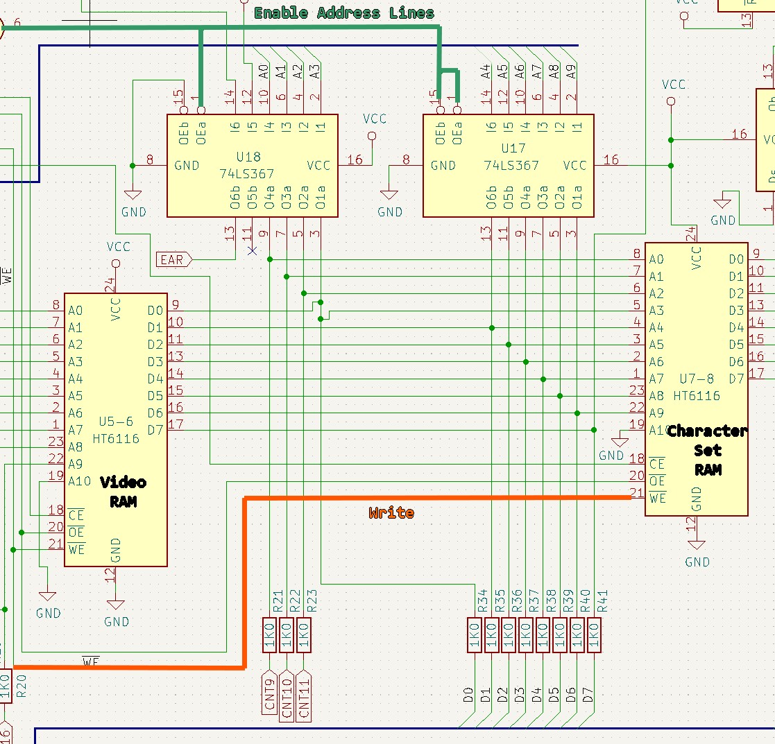
My solution was for me to delay the !WR signal by 60-80ns using 4 inverter gates. This ensured the address bits made it to the RAM before the write signal did.
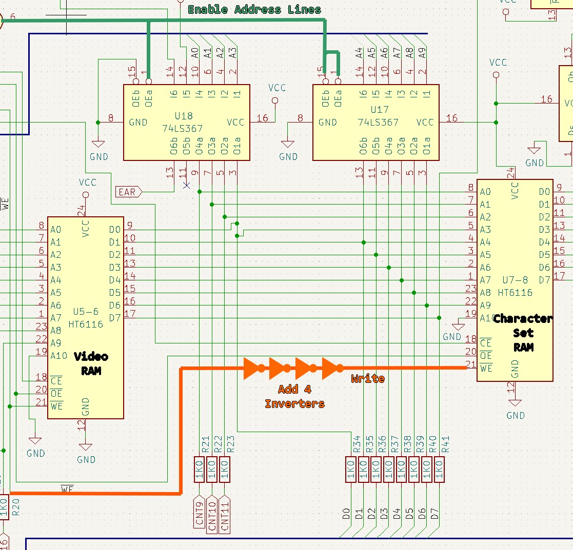
If you invert something twice, you get back the original, but you’ll introduce gate delay of about 15ns – 20ns per inverter. So the 4 inverters above ought to yield 60-80ns of delay. There was already a 74LS04 inverter IC with 5 unused gates on the board. The one gate that was used in the 73LS04 was already attached to the !WE line, so I only had to add 3 of the unused gates. The video linked to this post illustrates the changes to the schematic.
Making new Jupiter Ace Modules
Making new modules wasn’t difficult, though there are a few tricks I came up with for the edge connectors.
- The edge card connectors need to be “open” on the two ends. I made them by taking a larger-than-necessary connector and using a hacksaw blade to carefully cut off the ends.
- For a “pass-through” so you can piggyback one module behind another, I used a small stub board. I pushed the edg connector through the main pcboard, then bent over the pins at an angle so they would contact the stub board, then soldered it all together. You end up with kind of an upside-down “T” shaped module.
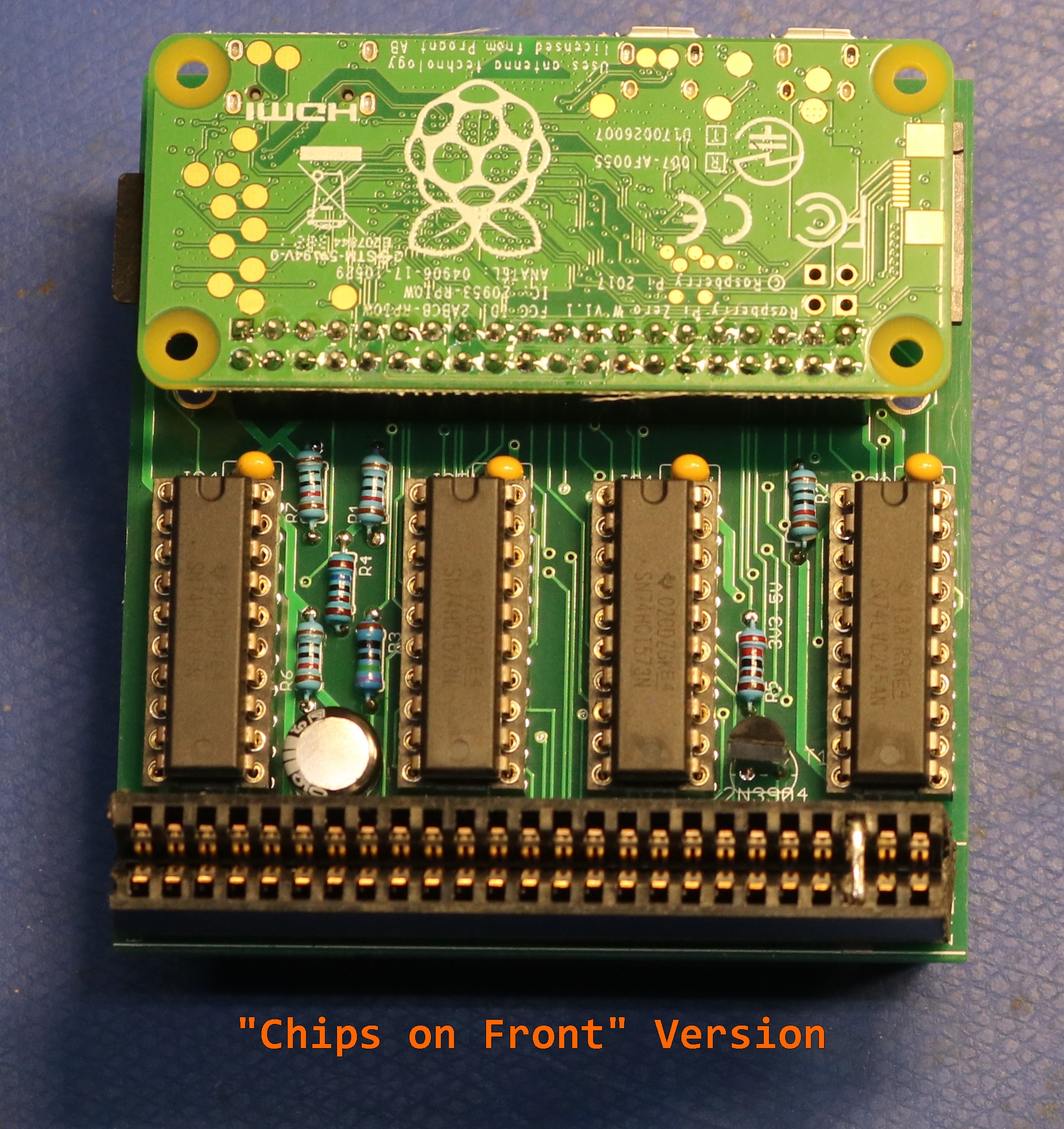
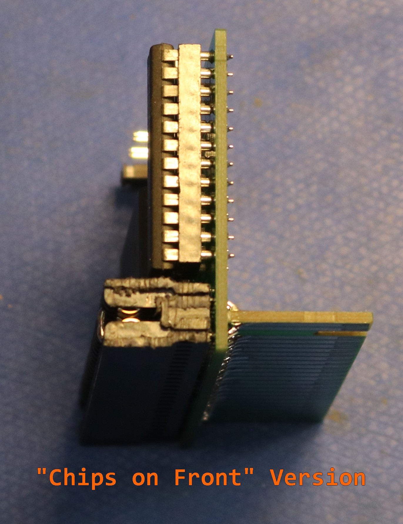
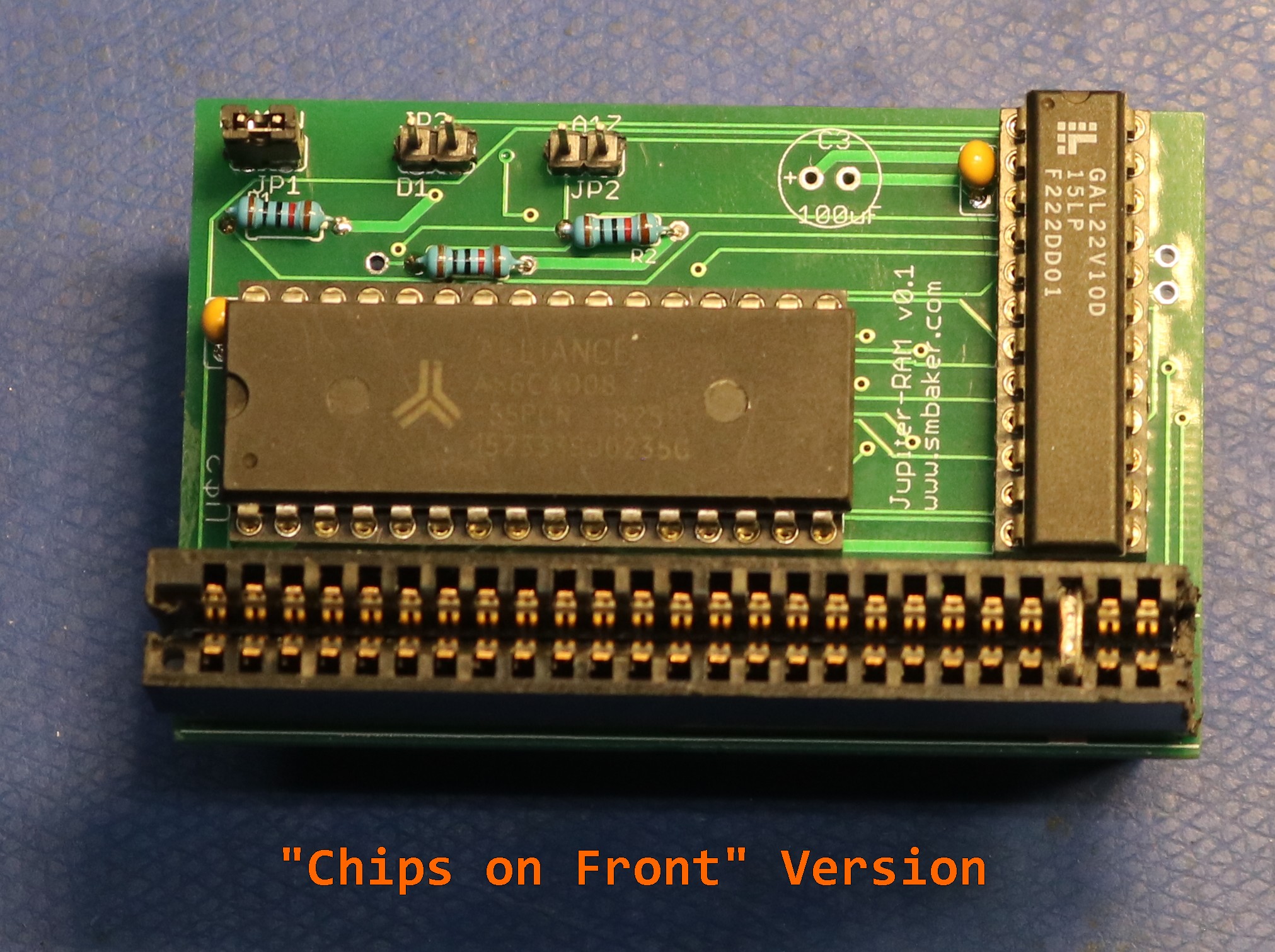
After I made the initial three modules, I realized that it would have made more sense to put the chips on the back, than to put the chips on the front. Doesn’t really matter for exposed modules, but if you ever want to put them in a case, the case won’t fill well if the chips are on the front. So I am redesigning the modules to move the chips to the back, but in the meantime this blog post will show the “chips on front” version.
(Note: You can’t just move the chips from one side to the other or move the edge card connector — it needs to be rerouted, thus I am fabbing new “chips on back” variants of these boards)
Designing a RAM board
The Jupiter Ace has a fantastically tiny amount of user program memory. Less than a kilobyte. FORTH is an efficient language in both time and space, but it’s not that efficient that it turns a kilobyte into a magically plentiful amount of space. Most people using a Jupiter Ace would probably go out and buy a RAM expansion for it. It’s also the only way to get most games to fit into memory.
The Jupiter Ace archive had several notes about RAM boards, including 96KB RAM module by Klaudiusz Fatla. Using Klaudiusz’s design as a starting point, I went ahead to design my own.
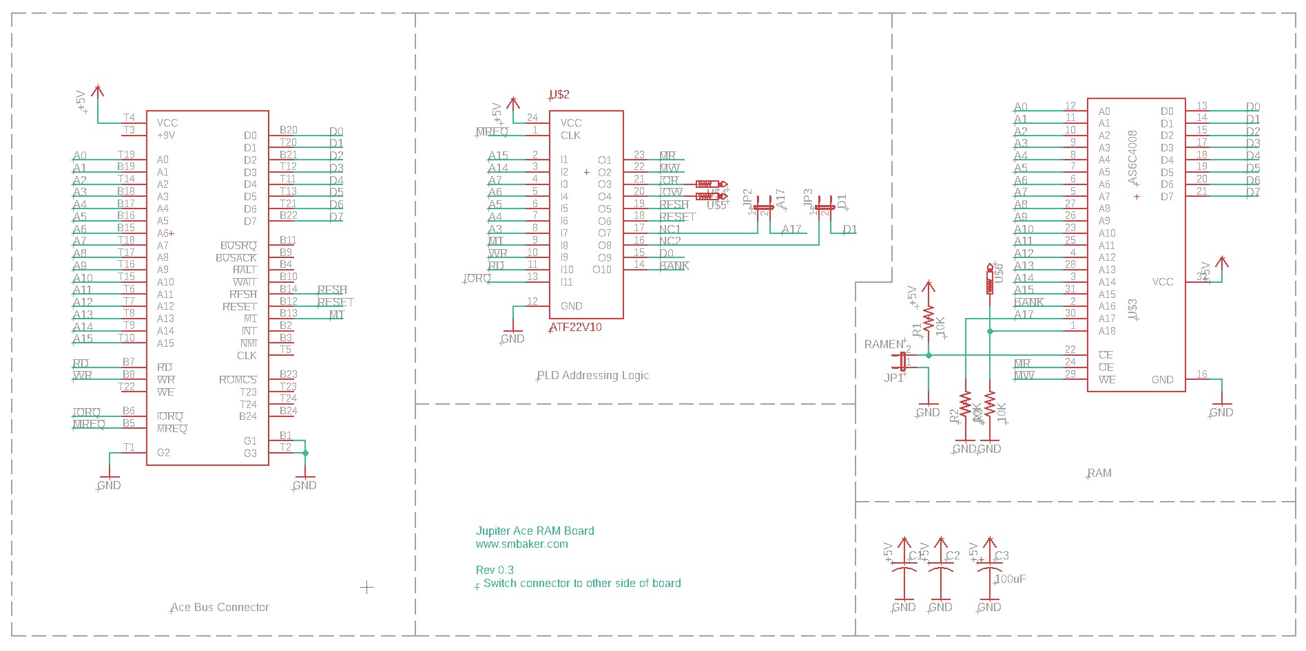
I ended up putting the logic in a GAL22V10D since I used those programmable logic devices in a lot of my projects these days. This affords the option of building a stock 48KB module, a 96KB module like Klaudiusz’s, or a bigger module of my own design. I plumbed the !RFSH line into the PLD so I could emulate Klaudiusz’s design, and I also added IO decoding and D0 and D1 so I could pursue a more traditional port-based design. Ultimately though I chose to just leave the board as a 48KB module where all you really have to do is decode the top two address lines:
/* for full PLD code, see github repo */
MADDR = A15 # A14; /* the upper 48K A15=A14 = 01, 10, or 11 */
BANK = 'b'0;
MR = MREQ & MADDR & RD;
MW = MREQ & MADDR & WR;
Here’s a picture of the RAM module
Designing a speech synthesizer
One of the first things I always do is to make a speech synthesizer for my brand new retro computer, usually using the popular SP0256A-AL2 speech synthesizer IC. So I set out to design one. There’s already a Jupiter Ace speech synthesizer called the Big Mouth by Martyn Davies. I chose to make my synthesizer compatible with the Big Mouth. Just like the the RAM module, I let a GAL22V10D do the work of decoding the IO address. Here’s a schematic:
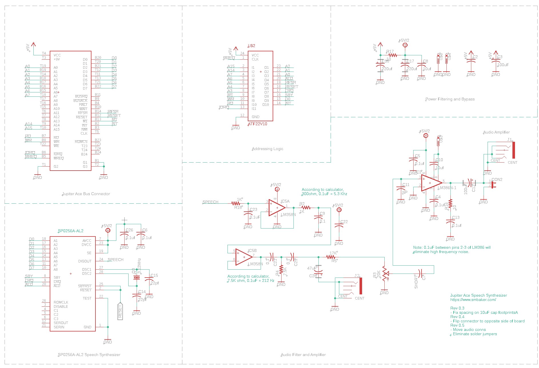
… and here’s the PLD code:
/* For full PLD code, see github repo */

FIELD ADDR = [A7..A0];

PHON_CS = (ADDR:0x45);
STAT_CS = (ADDR:0x47);

ALD = IOREQ & !M1 & PHON_CS & WR;

D0 = LRQ;
D0.OE = IOREQ & !M1 & STAT_CS & RD;
Finally, here’s a picture of the speech synthesizer board itself:

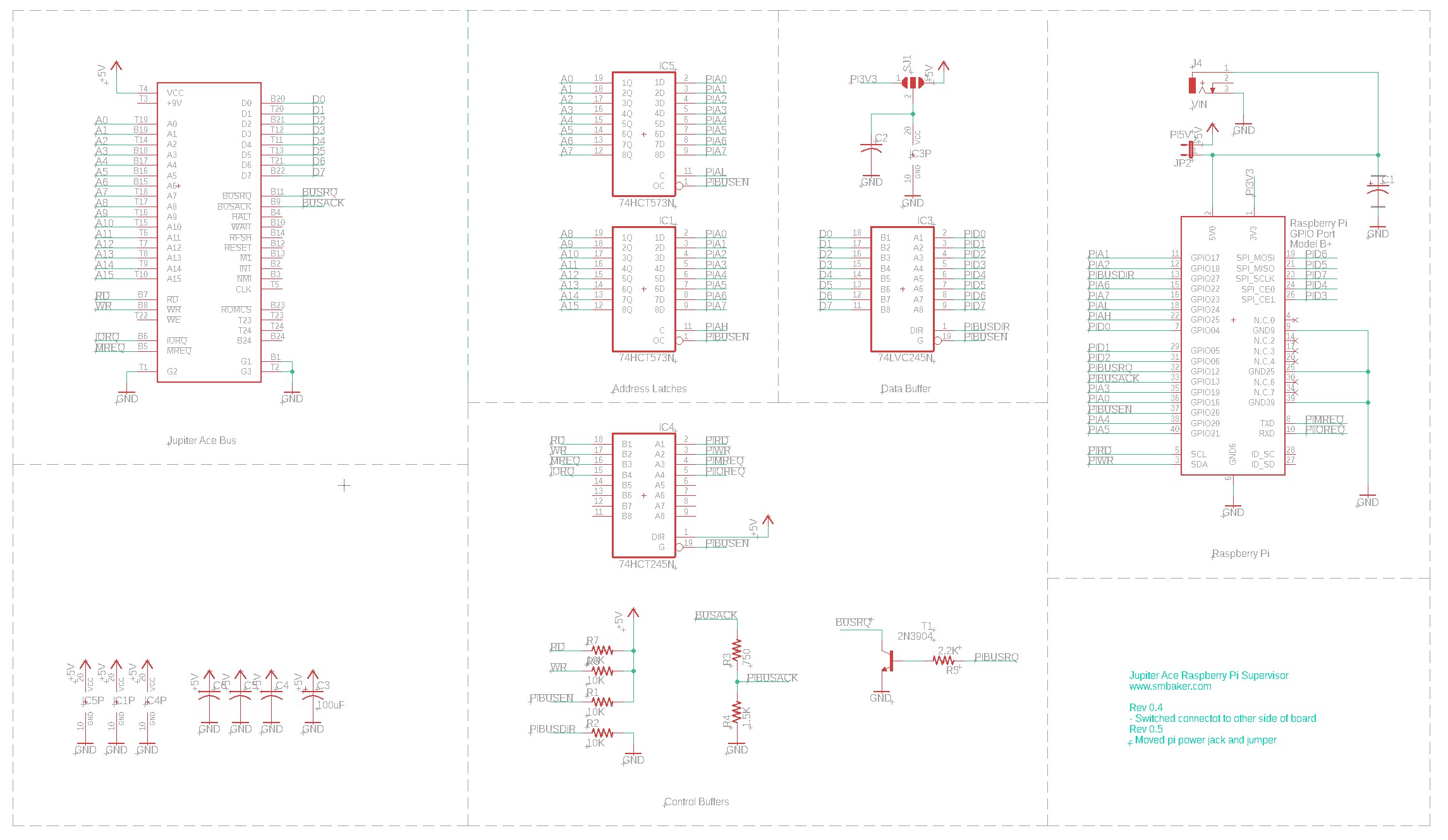
Designing the Raspberry Pi Supervisor
The Pi Supervisor is a board that I first built for the RC2014. I recognized how useful it would be to just pause the CPU and read or write memory. You can PEEK and POKE your retro computer from the convenience of your desktop computer, to see what’s going on inside the retro computer. You can even push whole programs into memory, or save the current state of memory. On some computers, such as the Jupiter Ace, I’ve been able to push keystrokes directly into the keyboard buffer and download screen captures. This lets me do software development from my Windows desktop across the room, yet still do it “on” the retro computer. Rather than laboriously type a whole program on the Ace’s keyboard, I can just paste the whole thing into the keyboard buffer. The schematic is below:
Here is the completed board: