In my quest to have a vintage paper taper writer, I converted an AKI TTS Keyboard to be controlled by pi and by serial:
Purpose/Motivation
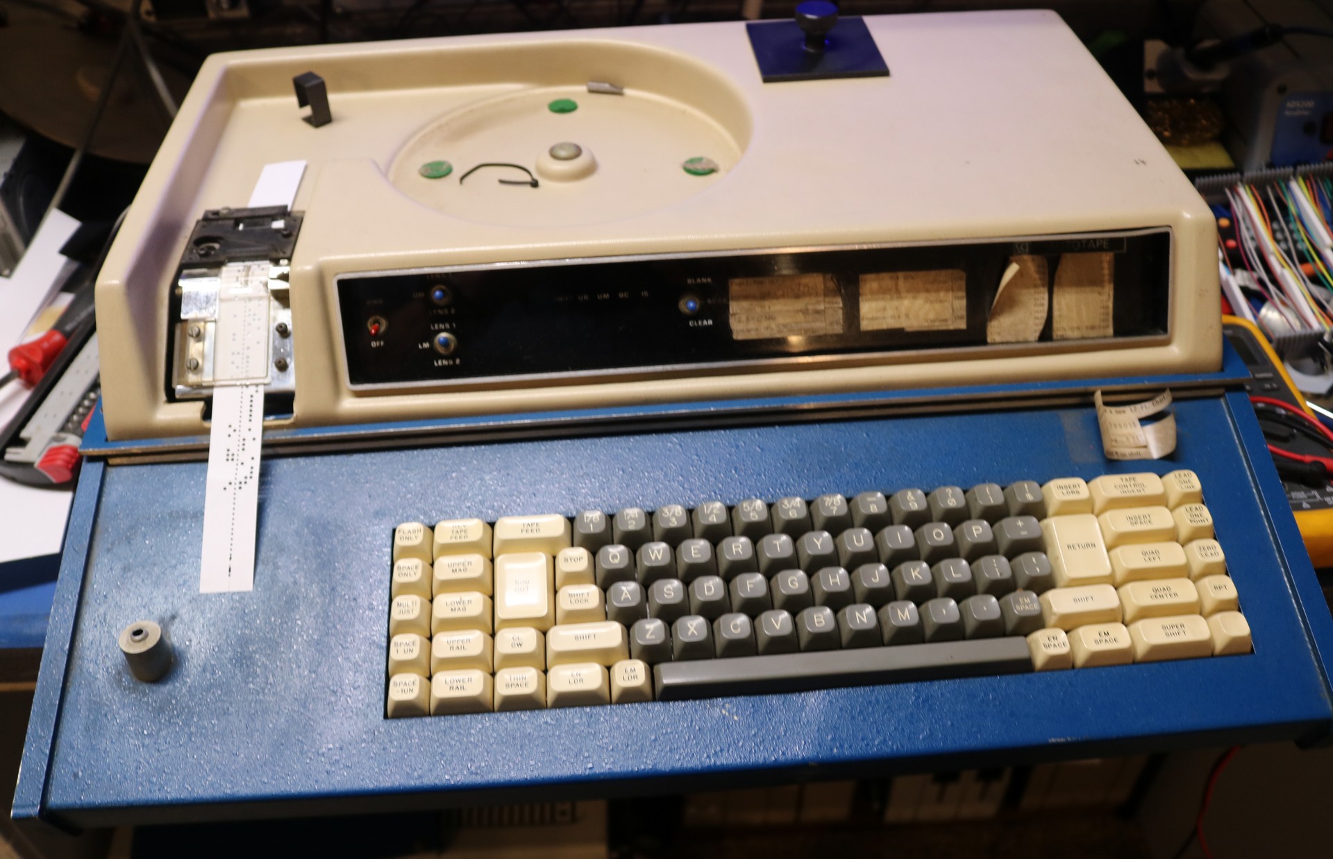
I’ve always wanted to play around with punched paper tape. DIYing a paper tape reader would not be a problem (see https://github.com/dhansel/PaperTapeReader) but DIYing a paper tape punch seems like it could be an incredible amount of work. Totally new to this, I started watching eBay for paper tape related items. In June 2023, a pair of AKI Teletypesetter keyboards showed up at a reasonable price, and I bought one of them, for approximately the starting bid value. Below is a picture of the best, as received:
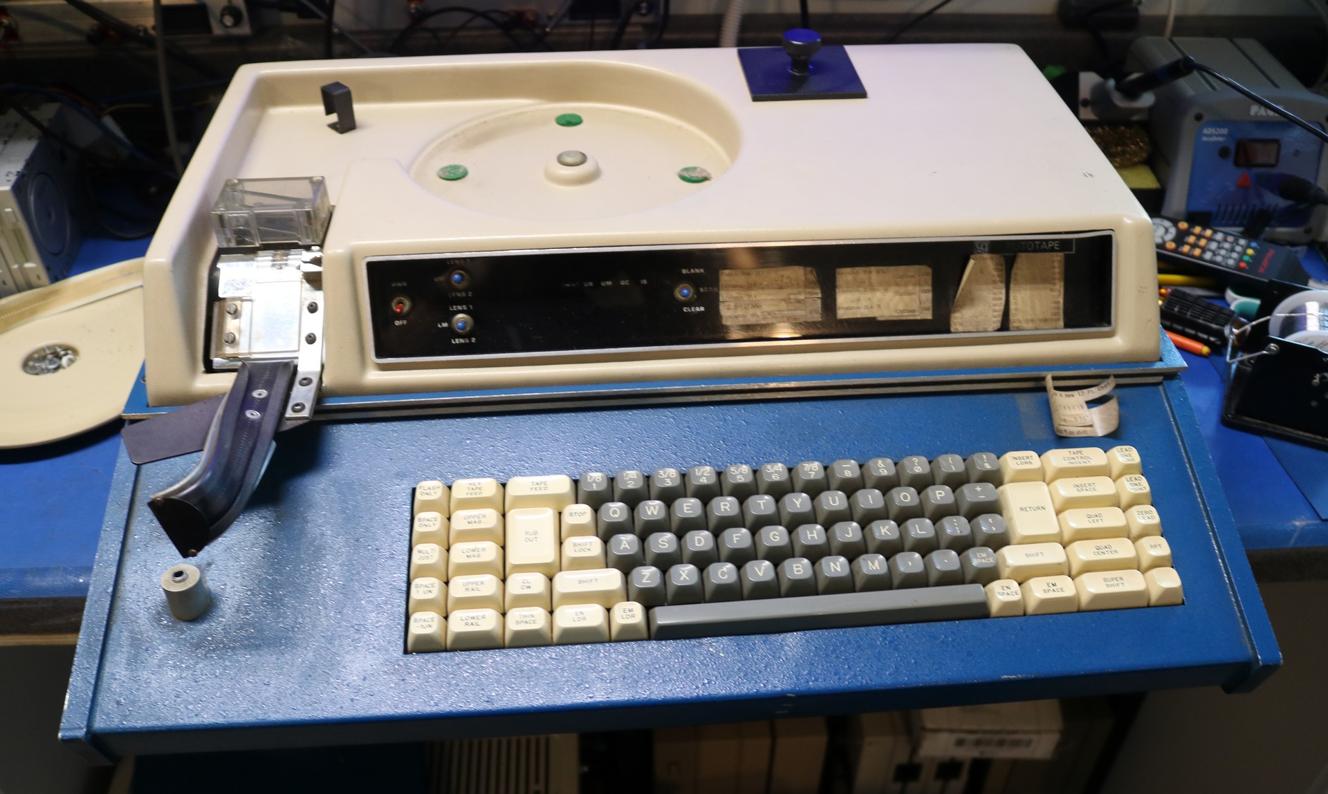
Note that there are no IO ports present on this thing. It’s purely a keyboard attached to a paper tape punch. What you type on the keyboard appears on the paper tape, letter-for-letter and key-for-key. If you push down <Shift>, that’s recorded on the tape. If you release <Shift>, that’s also recorded. There’s no built-in correction capability — if you push the backspace key, <Rubout>, that too is encoded as a sequence on the paper tape.
Other can a couple of single LED indicators, there is no visual feedback.
Restoration
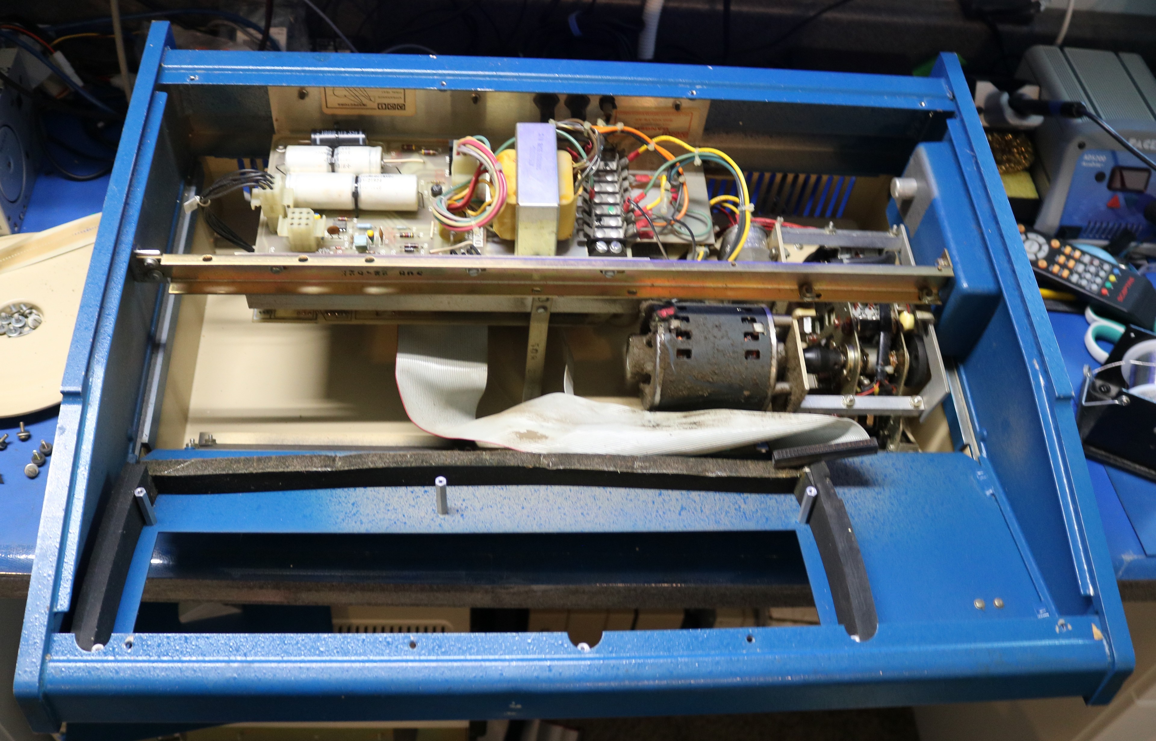
The eBay listing said the keyboard would not punch, and true to description, it did not work. It produced a motor-running noise when plugged in. A few LEDs would momentarily light, including one for the capslock. That the capslock would not stay lit led me to suspect there was a power and/or logic reset problem occurring. First I removed the lid — it comes off with four screws:
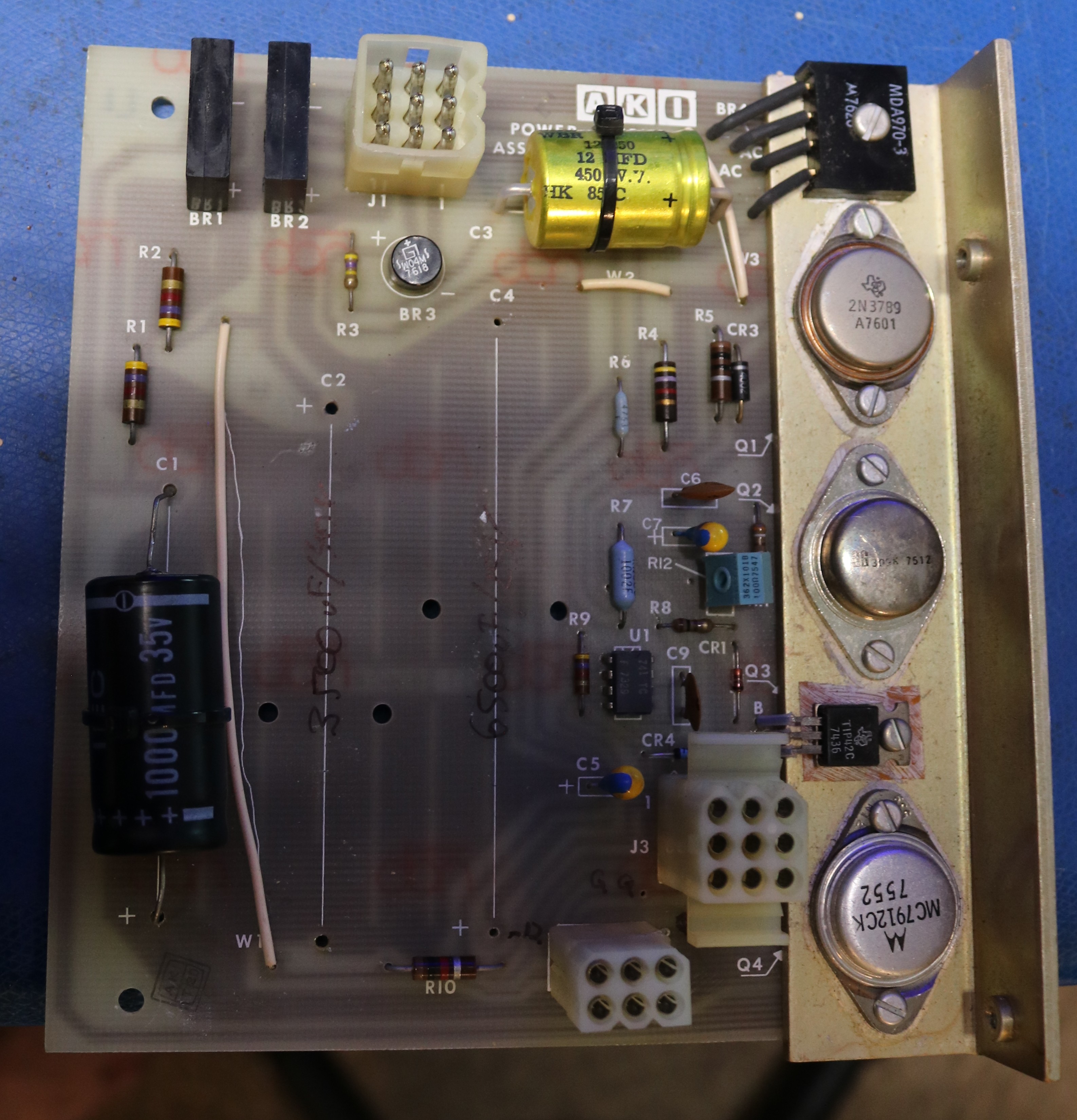
Removing the lid and checking a random 74XX logic IC, I found only about 3V of voltage across its power leads with my multimeter. Had I connected an oscilloscope, I’m sure we would have seen that this was 3V average power, oscillating at 60Hz. This would have been a telltale sign of bad filtering capacitors. I didn’t even bother with the scope, I proceeded to flip the unit over and take a look at the power supply.
See those two ancient-looking silver things? Old electrolytics. Here’s a closer view:
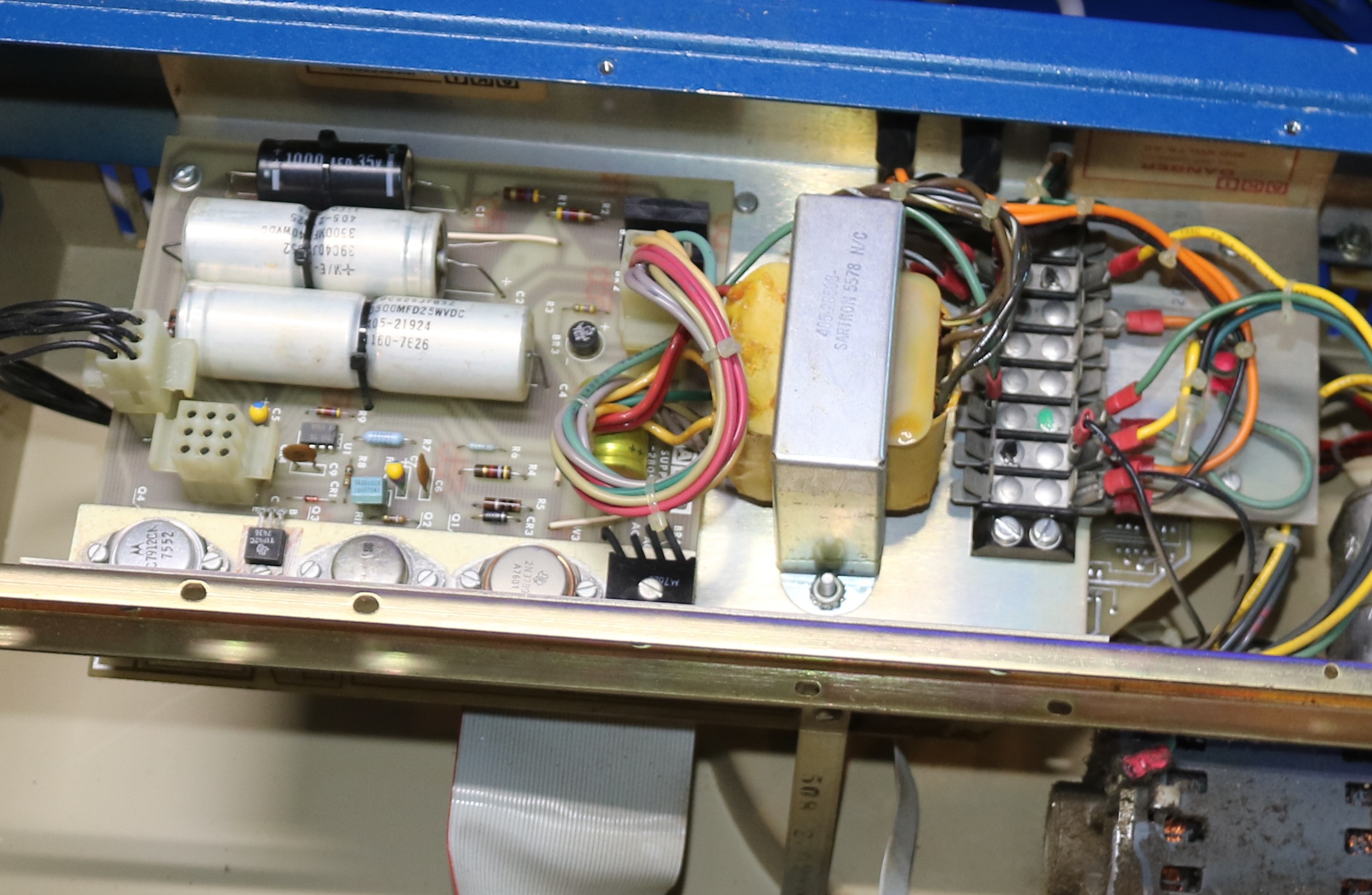
I removed the power supply board, and removed the two electrolytics:
I had a 6800uF/25V, but the closest I had to the 3300uF/35V was a handful of 3300uF/25V. I decided to series/parallel them to get 3300uF/50V:
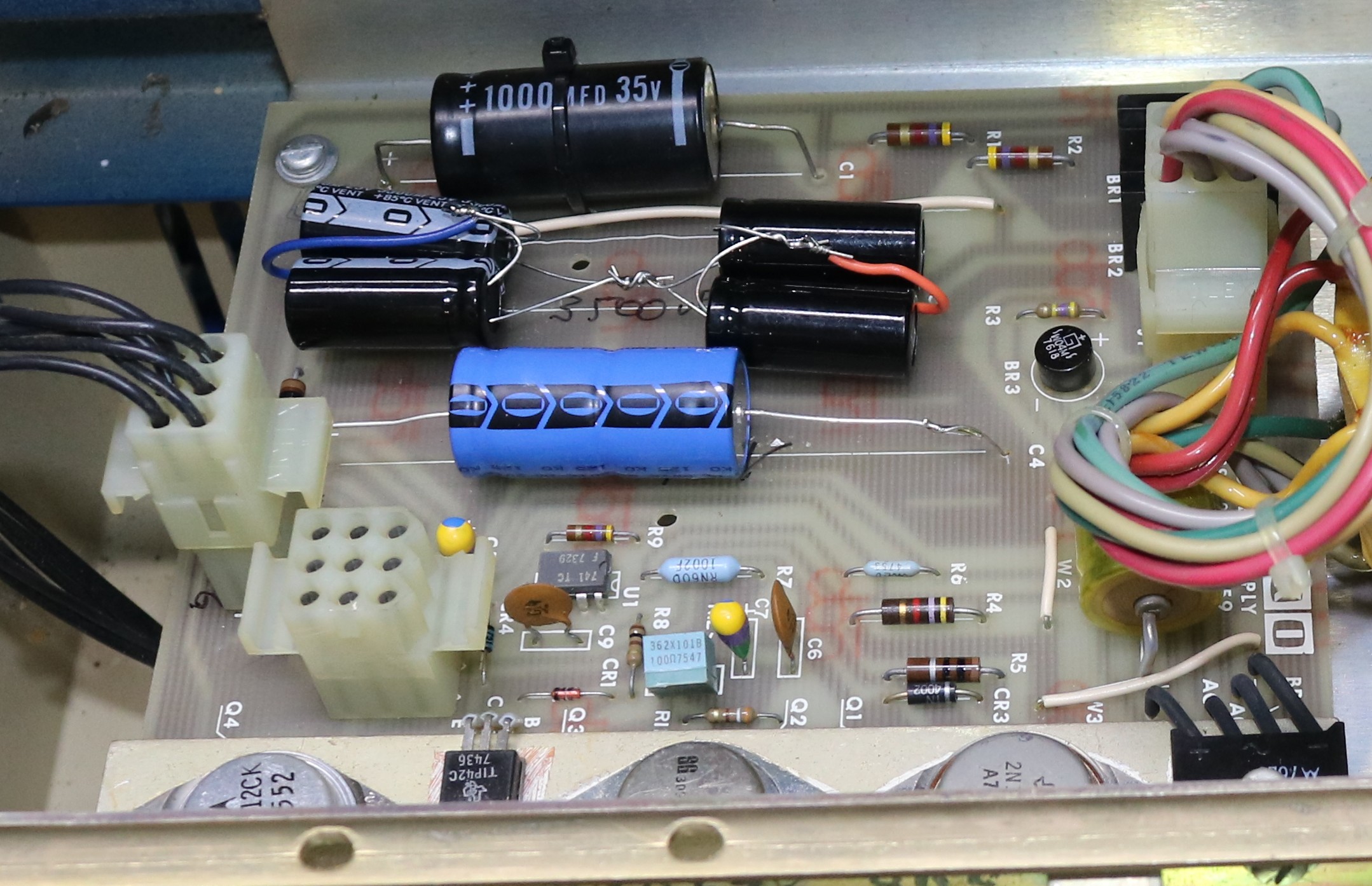
This was enough to get the punch up and working!
Unbeknownst to me at the time, some of the punches were “sticking”. If I hit the “S” key and the “U” key I would see the same sequence, 111000 punched to the tape. The two outer 1s were causing the middle 1 to always fire. I sprayed some deoxit on the punch mechanism and worked the keys extensively and was able to resolve this issue. Diluting down the grease with deoxit is not necessarily a good idea, and it probably needs a thorough cleaning and regreasing, but this was sufficient to get it to punch correctly.
Reverse Engineering the logic board – Drivers
First, I pulled the keyboard and took a picture of it:
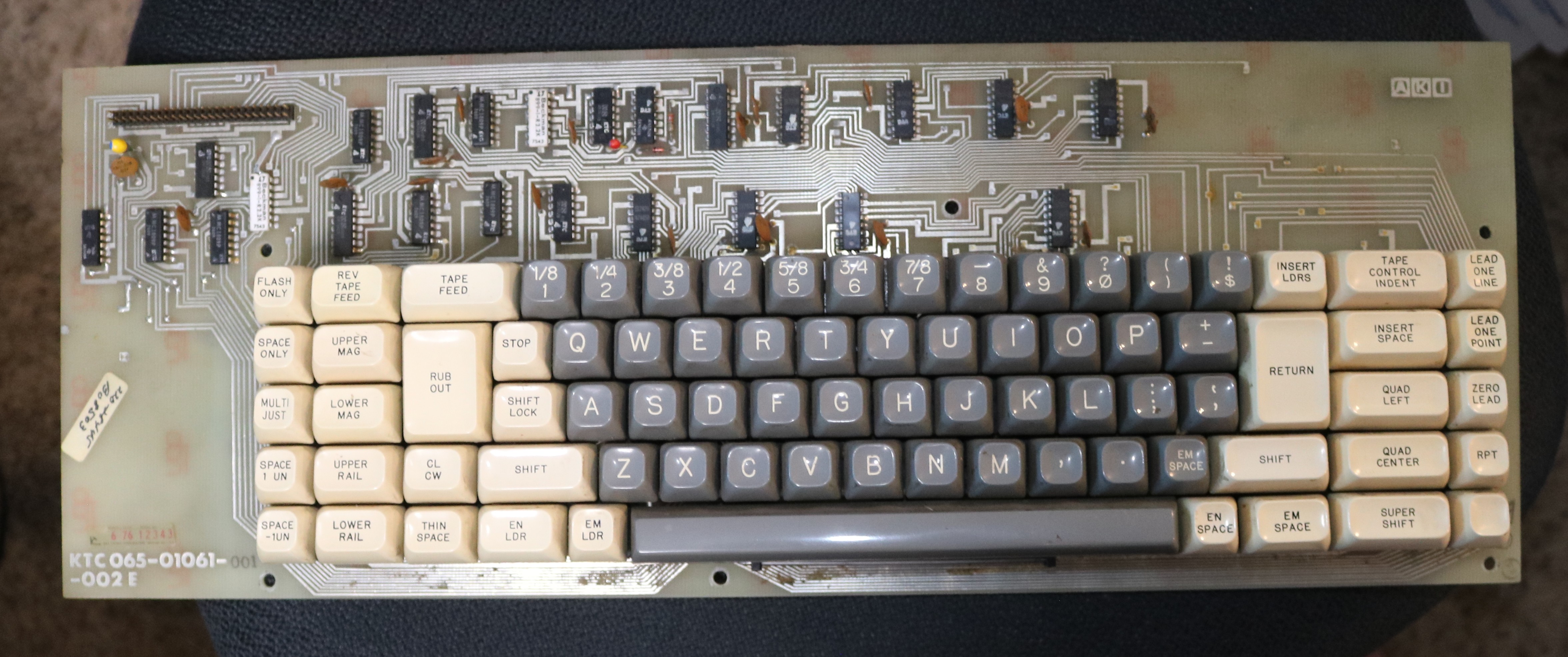
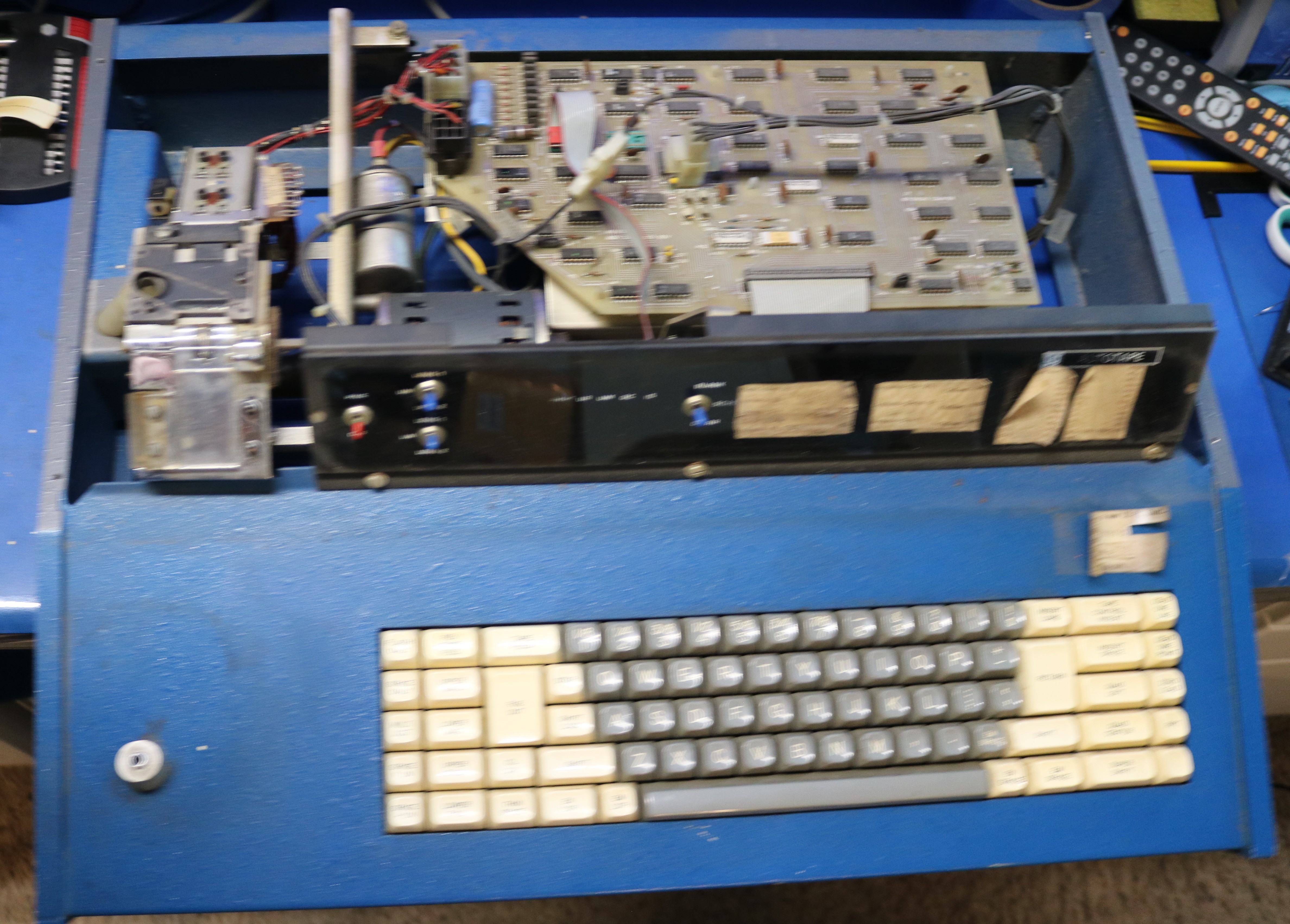
I didn’t do much work with the keyboard, but instead I focused on the main logic board:
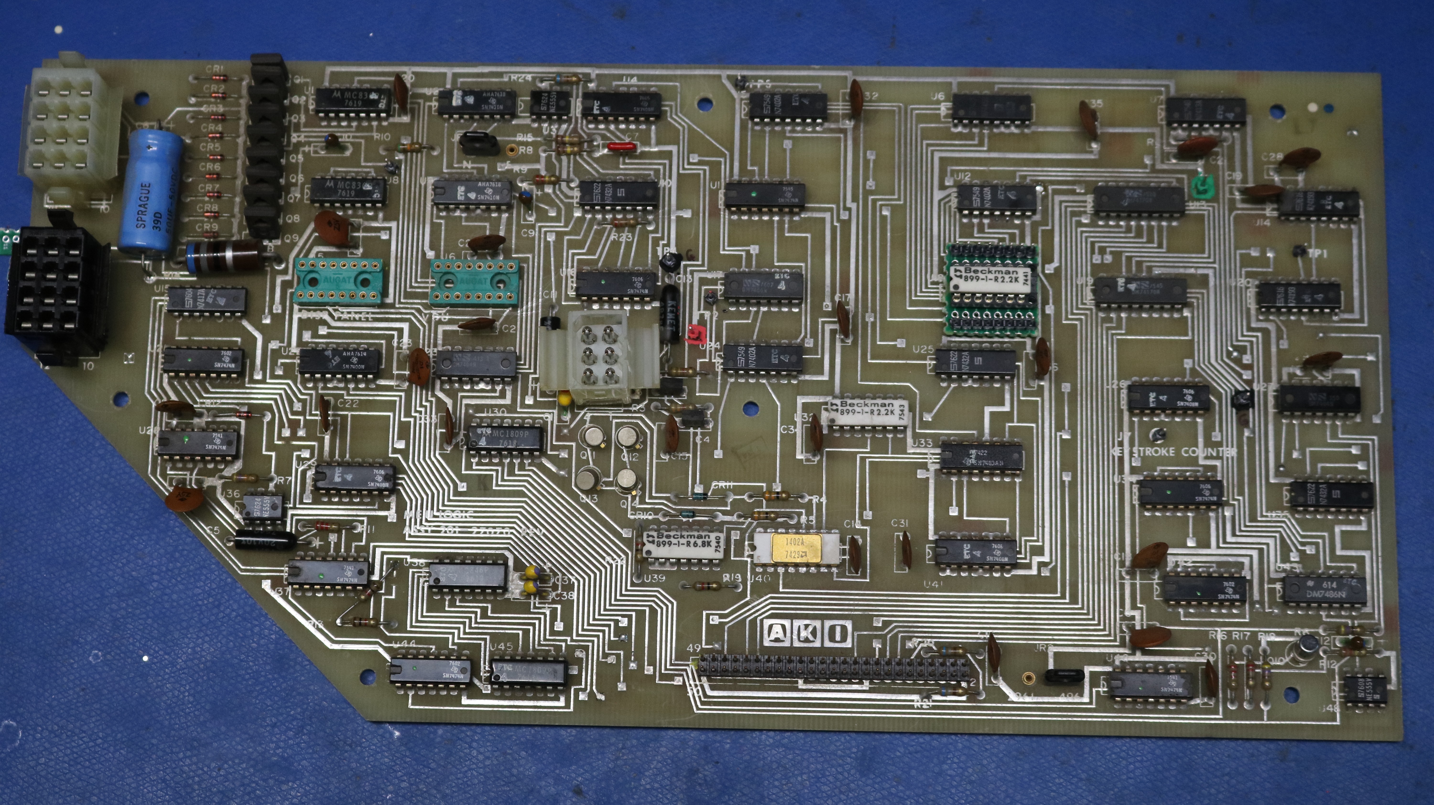
The white and black connectors on the left go to the punch mechanism. The white connector in the middle is the power supply. The 50-pin header center-bottom goes to the keyboard. You can see nine power transistors in the upper left that are obviously the drivers for the punch solenoids. I started working on a schematic:
You can find the full schematic (as much as I reverse-engineered) in my github repo. For now, let’s just take a look at a couple of drivers. There an MJE800 power transistor (Q1) that drives the punch by pulling the punch solenoid down to ground. There’s a kickback diode (CR1) associated with each transistor. The MJE power transistor is driven by an inverter (U1A) which is in turn driven by a 7410 triple-input NAND Gate (U9B).
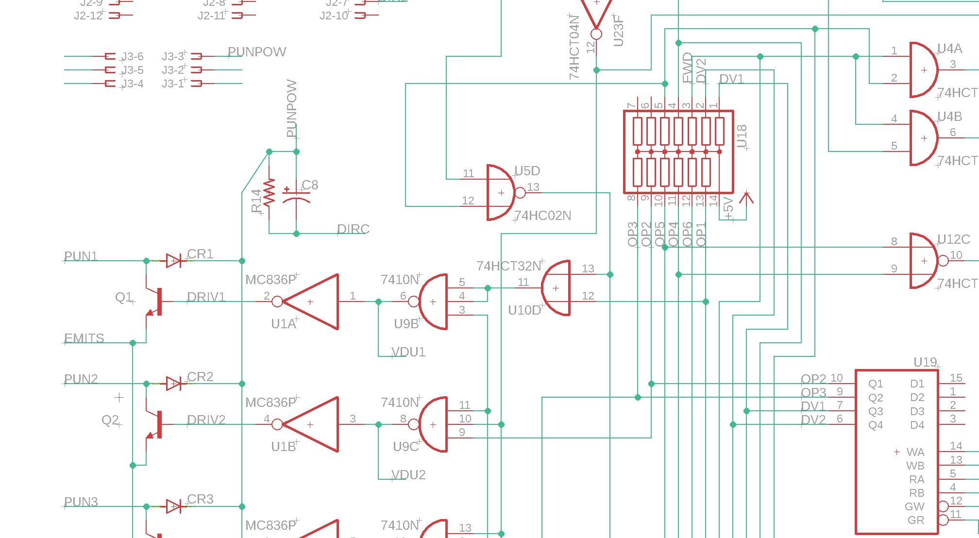
Here’s where it starts to get a little bit weird. Every bit in the punch eventually makes its way over to U18, a DIP-14 pullup resistor. Some of them (like Q2-U1B-U9C) have a line that directly heads over there. Others, like (Q1-U1A-U9B-U10D) go on a more roundabout path but eventually make their way to a pullup in U18. I’m not sure why the divergence.
Anyhow, those pullups in U18 are eventually driven by U19 or U13 which are open-collector register 4×4 register files. I think these are used as a simple 4-deep queue, perhaps to iron out any bumps between the typists speed and the punches speed.
Each driver is also enabled by two other lines. One of these is a signal that is engaged only when the punch is in “forward” mode — you only punch data bits while moving forward not backward — makes perfect sense. The other is via a 555 timer connected to a sensor on the punch:
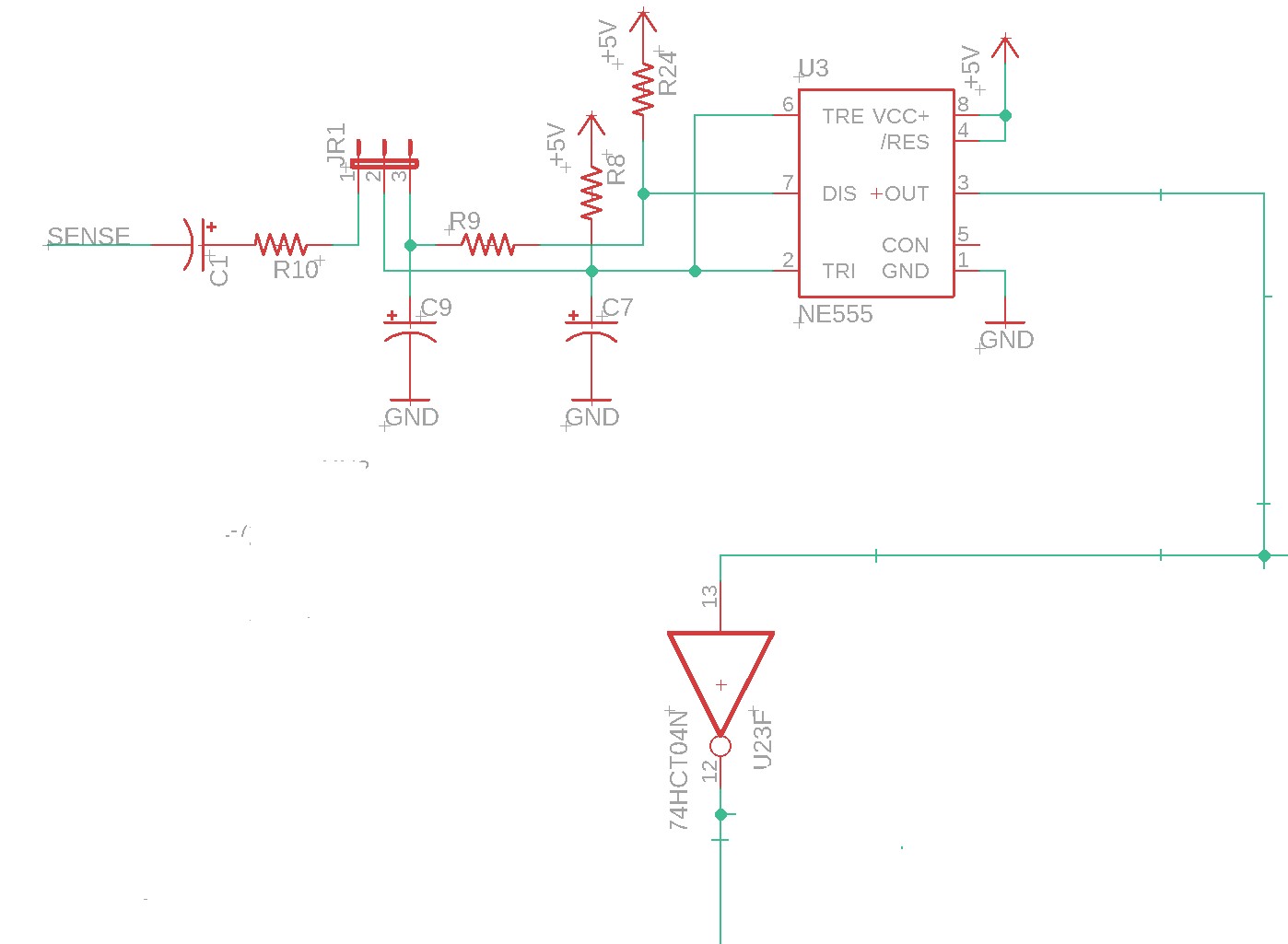
Looking at a 555 cookbook, the closest I found to this circuit is a “sinewave to squarewave” converter, and I believe that’s more-or-less what it does. “sense” is a magnetic pickoff from the punch that changes as the punch motor turns. The output is a square wave that is used to determine what cycle the punch motor is in. Apparently, it’s important to only fire the solenoids at just the right time for the punch cam to engage them.
Reverse Engineering – Control Logic
Now here’s where it gets really strange. I had traced the drivers to a pair of 4×4 register files (U19, U13) with open collector outputs, and it seemed like if I wanted to control this from a pi, it would be simple enough to just output my signals onto those open collectors. However, I found they’re constantly getting spammed with a free-running 8-bit counter. This one:
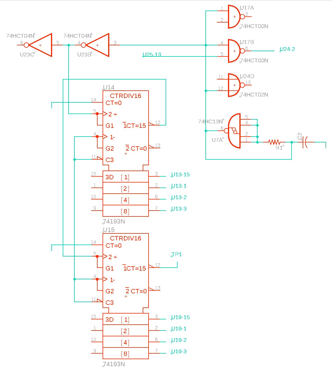
U7A forms a schmidt-trigger oscillator, and it’s fed into U14/U15 which are an 8-bit counter. These are in turn fed into the 4×4 register files, and written on every cycle of that oscillator. Generally the address bits of U13/U19 are set to the same, the read output it enabled, so this free-running counter is constantly spamming the NAND gates that feed the solenoid drivers.
My suspicion is that this counter is sent to the keyboard pcboard, and when a key is pressed, it causes the address to increment on the register file, thus queuing the current keypress.
Controlling this with a raspberry pi
I ended up going with a relatively brute force approach:
- Disconnect the 4×4 register file GR signals from ground and connect them to the pi. This allows me to effectively turn off the 4×4 register files, leaving their open-collector outputs pulled up to a high state by U18. This prevents the spamming of that free-running 8-bit counter into the drivers.
- Put the bits I want onto the pulled-up driver inputs (the ones that would be driven by the 4×4 register files, but are not because I disabled them in step 1)
- Electrically trigger the “tape forward” button. This will cause the keyboard to do all the necessary synchronization to engage the solenoids to move the punch forward and punch the index hole. Since my desired data bits are set in step (2), my holes get punched.
Here’s a schematic of my pi board:
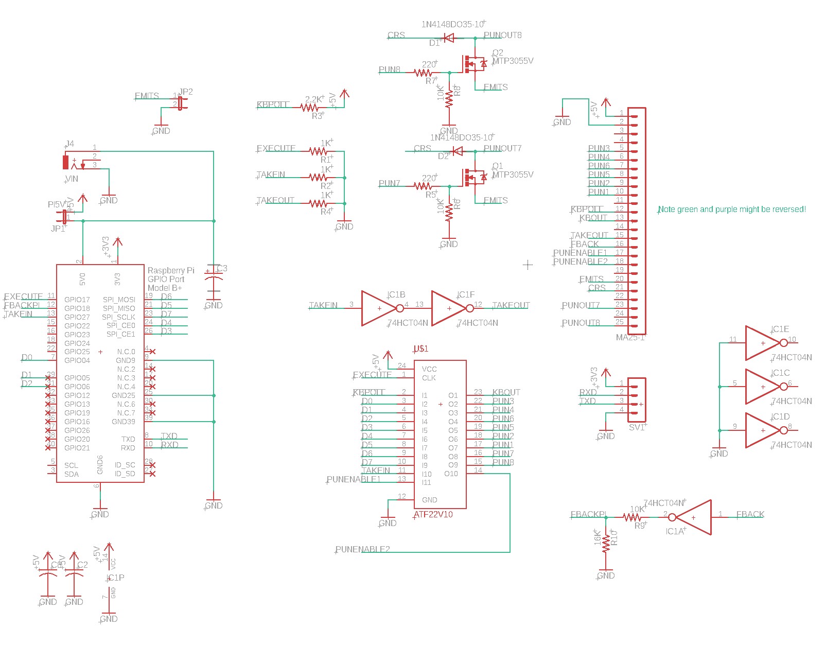
Here I use an ATF22V10 (or GAL22V10D) PLD to do some interfacing. It functions as an open collector, taking the pi’s GPIO4-GPIO11 and putting them to the appropriate drivers. It also handles asserting the signal to shutdown the 4×4 register files. Finally, it handles pushing the tape-forward button. Pushing the tape forward button involves watching for a poll (/KBPOLL) signal and then pulling down /KBOUT to simulate a key press.
Finally, the AKI keyboard only implements a 6-bit driver for the punch. The punch mechanism is however, an 8-bit punch. Two of the solenoids are simply undriven. So I used MTP3055V mosfets to drive those solenoids.
Prototype
I assembled the prototype on a piece of perfboard. It’s kinda ugly…
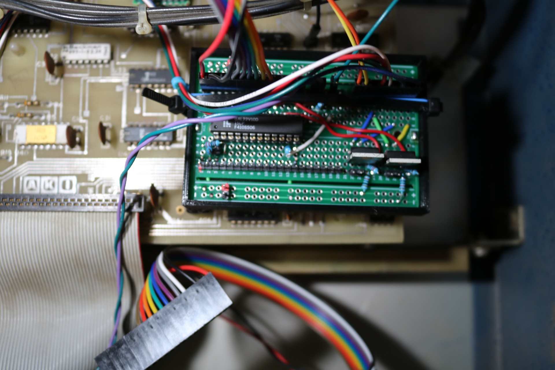
This also involved modifying the logic board to connect to the pullups at U18, disconnecting the GR signals at U13/U19 and wiring them to the pi, and connecting various wires for the two mosfet drivers. By the time it was all said and done, it turned into a ratsnest of wiring.
Serial Control
The ultimate goal was serial control via my H8 and/or RC2014 computers, not control from a raspberry pi. This is easy to do using a pi as the pi has RX and RX lines. I used a commodity TTL-to-RS232 driver board obtained from Amazon and wired it to the pi. My python program will take the serial coming into the pi and output it to the punch.