In this blog post, I create a new calibrator and a new amplifier for my Drake R-4C ham radio receiver.
Background
I’m relatively fond of these old drake tube ham radios, and I decided to upgrade my R-4B to an R-4C.
Note: many people don’t consider the R-4C to be an upgrade to the R-4B. While it came later chronologically, and included some modern technology such as a few transistors and crystal filters, it also moved much of the functionality to paid add-on modules, and it introduced an energy wasting / heat spewing amplifier stage.
Anyhow, the R-4C that I purchased came complete devoid of any options. It was utterly and completely stock. This blog post will chronicle some of my steps in upgrading the R-4C. I will mostly stick with doing period-accurate upgrades, what people would have done back in the day.
Crystal Calibrator
The crystal calibrator was an option that plugged into a four-pin socket in the R-4C. It produced a tone every 25 KHz on the band and could be used to accurately align your receiver to a particular frequency. It used a 100 KHz crystal, together with a capacitor to tune the oscillator exactly on frequency. The oscillator was divided in two and then divided in two once again, using a 7473 flip-flop IC. The schematic of the calibrator, reproduced from the R-4C manual, is shown below:
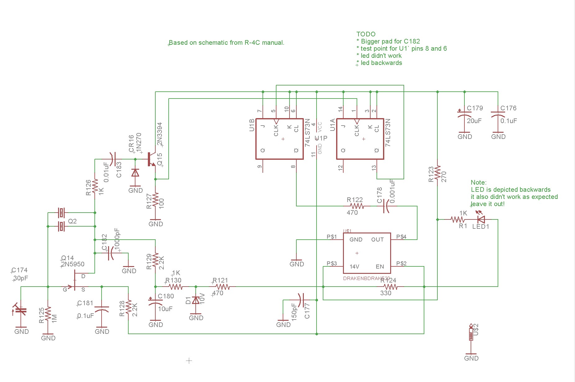
It is critical that you use a SN7473N and not a 74LS73 or 74HCT73. When I tried the newer logic families they did not work, producing spurious triggers leading to erratic behavior. I tried to add a LED, but it did not work out properly — I expected the LED to be unlit when the calibrator was off, but there was enough leakage to dimly light it. Leave the LED out.
The board I built is shown below. Note that the red trimmer pictured below should probably be green rather than red. Red is 0-20pF and green is 0-30pF in the typical assortments. Also note that the picture shows a 1000pF monolithic ceramic capacitor for C182. This should be a 1000pF silver mica cap instead.
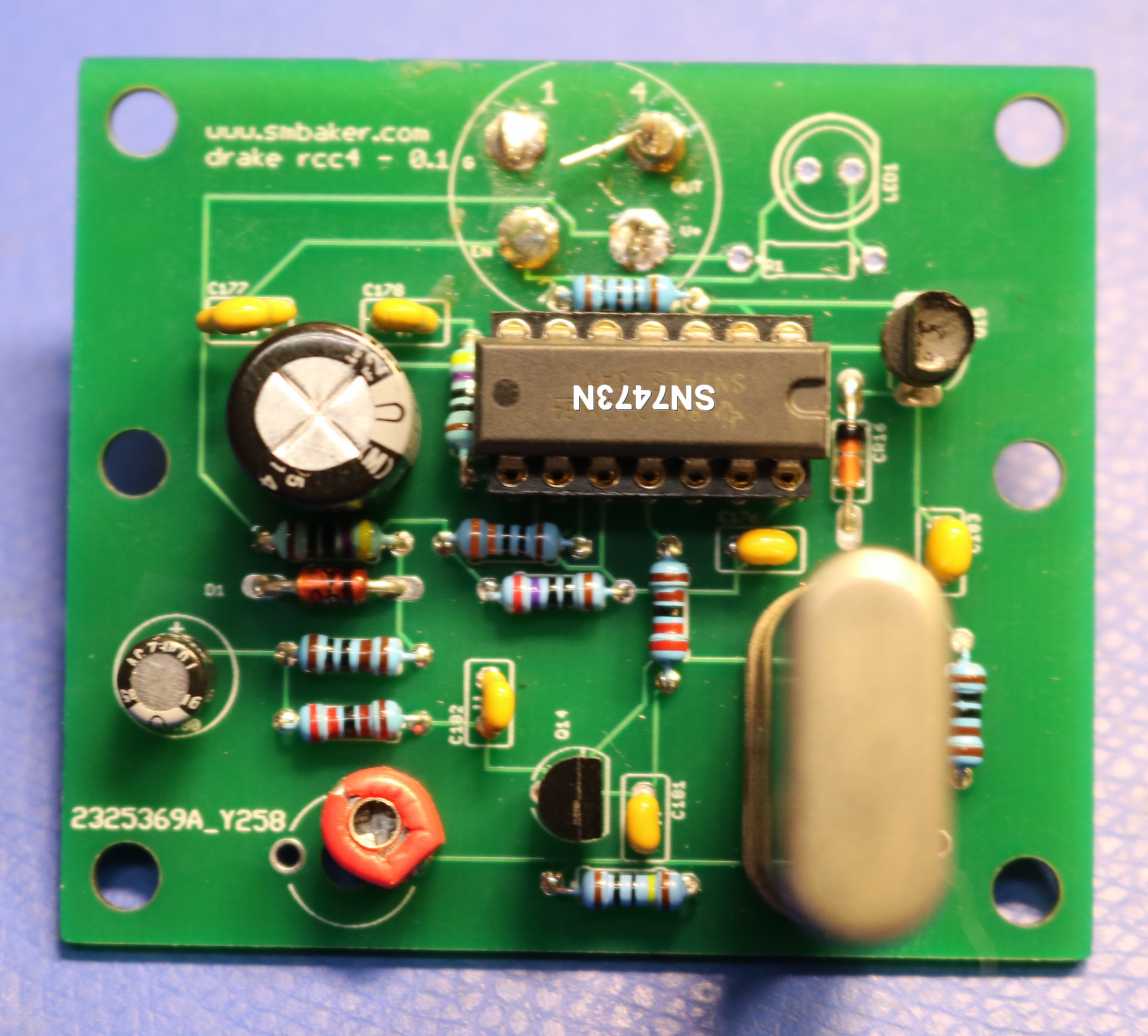
Note: Use *green* trimmer cap, not *red* trimmer cap.
Note2: Use a Silver Mica Film cap for C182, not a monolithic ceramic
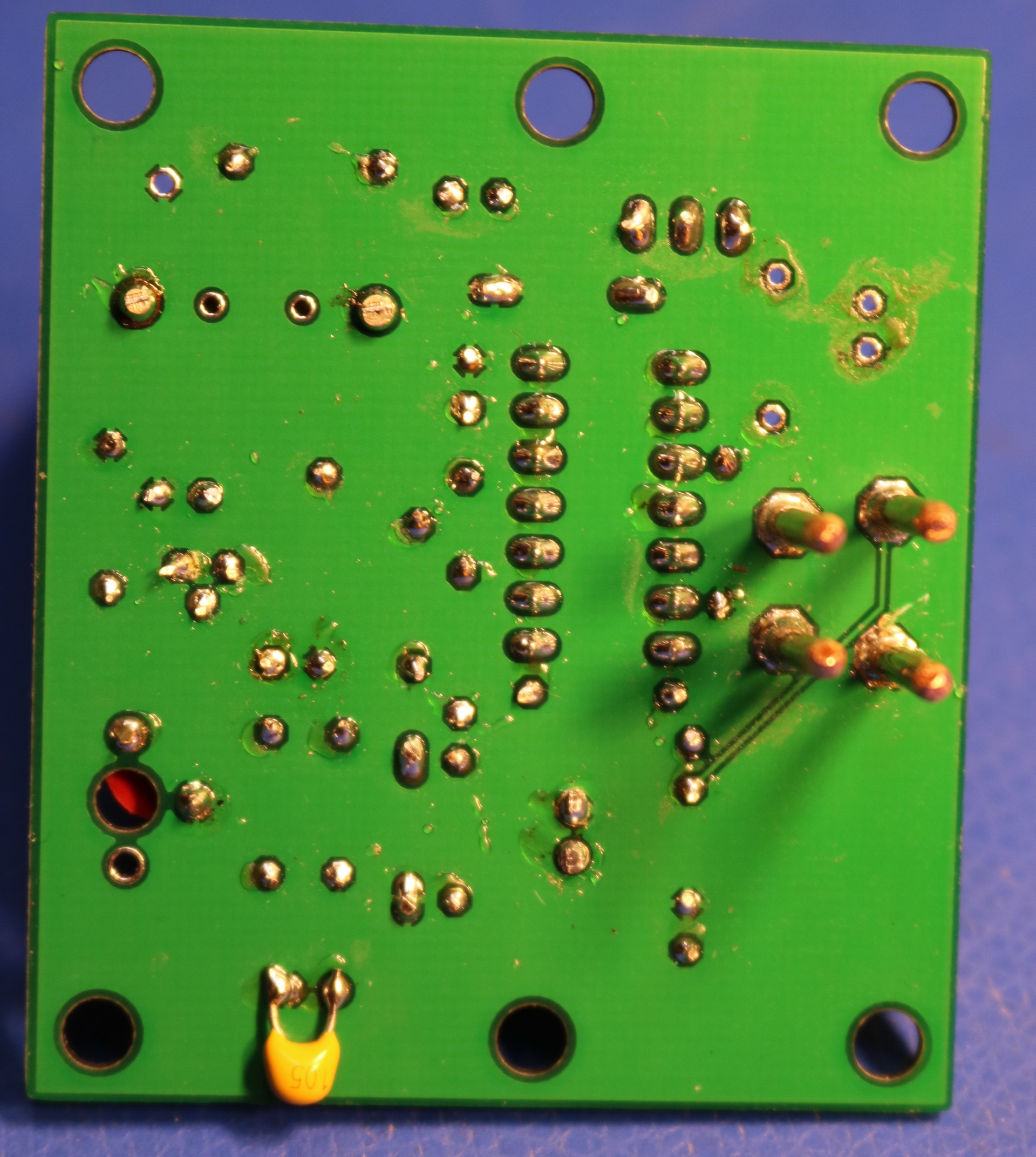
The socket pins are 12ga copper wire, from my local hardware store. Note the additional bypass capacitor on the bottom; I’m not sure this was necessary — I added it while trying to diagnose a problem.
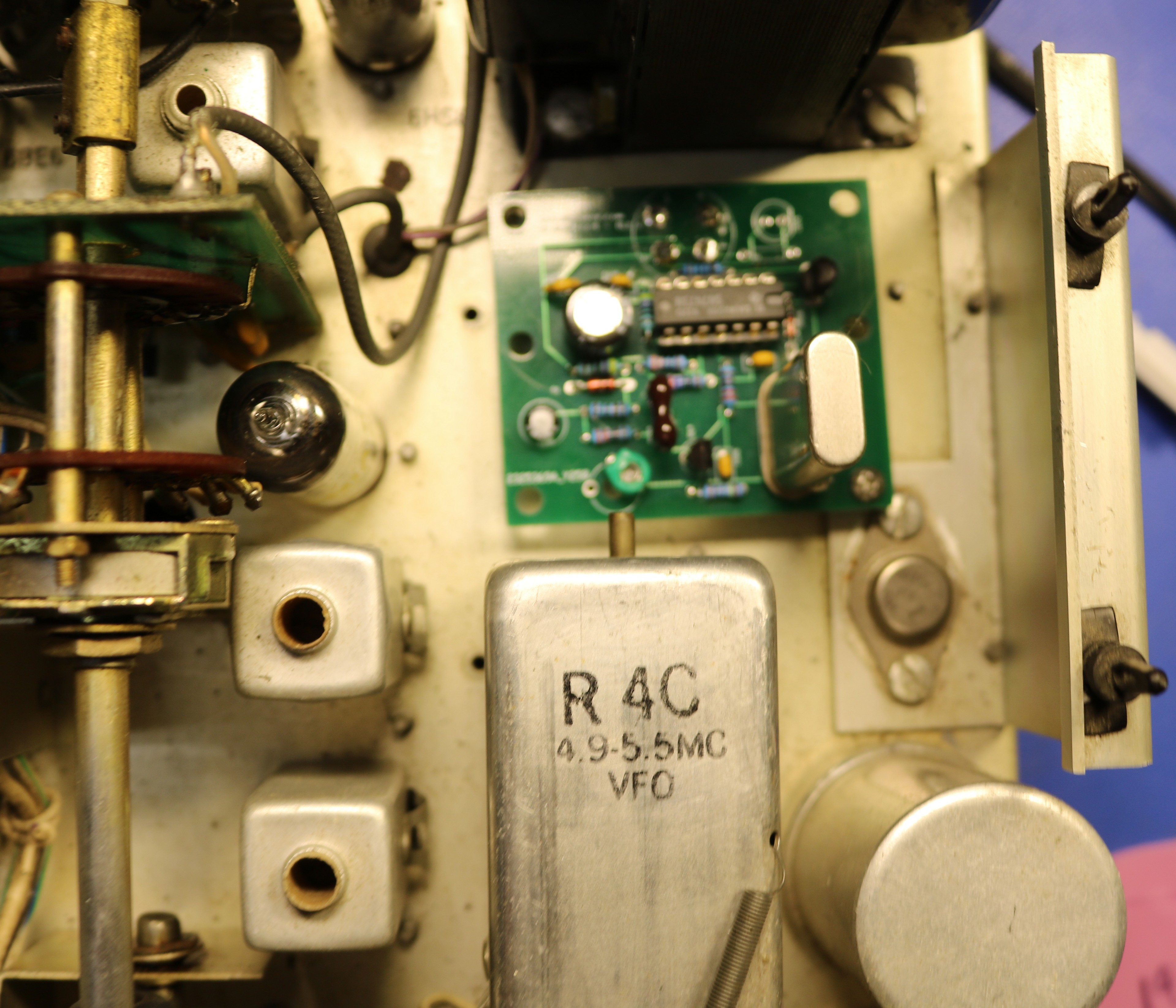
Below is a picture of the calibrator mounted in my drake:
Amplifier Modification
The R-4C amplifier is an inefficient design that dissipates a ton of heat. The heat is dissipated from the power transistor in the picture above right next to my calibrator board. It’s also right next to the VFO, and heat near the VFO can lead to drift. It’s surprising that Drake use this amplifier design when alternatives were available.
In 1979 Bob Sherwood published the design for a replacement amplifier based on the popular LM383T amplifier IC. I’m not going to discuss the design, as Sherwood’s article will do a better job than I ever could. Below is a schematic based on that article:
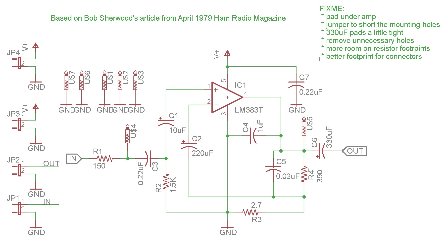
I produced a board and installed it in my Drake R-4C:
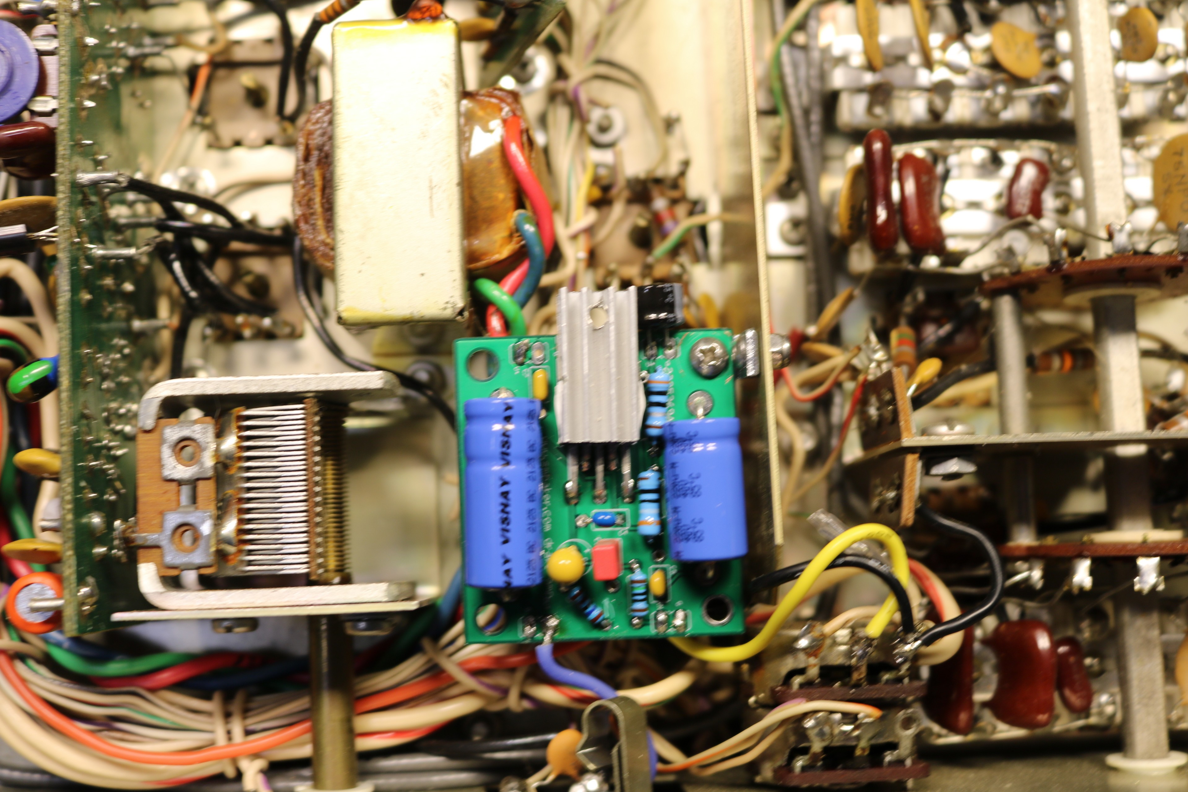
Sherwood’s article has a couple of cautions. First, that the length of the leads on the 1uF capacitor are exactly 3/4″ long. Second, that the board is only grounded via the ground wire to the audio pot and not grounded to the chassis. I found this didn’t matter; my board is grounded via a little metal L-bracket as well as via black wire to the audio pot.
When I do revise this board, I’ll probably add an option to isolate the L-bracker from the ground, so that Sherwood’s instructions can be more easily followed.
I have a heat sink glued using thermal adhesive to the LM383. I don’t know whether or not this is necessary.
The first problem I ran into was when I accidentally installed a 2.7K resistor instead of the 2.7 ohm resistor. This caused low volume, high heat generation (200+ degrees F), hum, and probably a host of other problems. Make sure you get the component selection correct.
The second problem I ran into was that the board became unstable at high settings of the AF control. It would appear to oscillate, and pull down the V+ supply considerably, until the filter can cap hit rock bottom, and then it would recover. This appeared to be due to a bad 1uF capacitor across pins 3 and 4 (C4 in my diagram). I replaced my junkbox capacitor with a known good mouser cap, and I made sure to lengthen the leads as Bob Sherwood suggested in his article.
You can see an additional 100uF capacitor mounted at a right angle along the back of the board. That was one of my interim attempts to resolve the oscillation problem mentioned above. It’s probably not necessary.
Resources
- www.github.com/sbelectronics/drake my github repo containing gerbers for the pcboards if you wish to make your own.