In this post, I make a battery-operated Wifi trigger to turn on the master valve for my sprinkler system.
Purpose
The way the pipes are configured for the sprinkler system, there’s a master valve in front of the yard hydrant that I use for my garden hose (there are reasons for this, but they are due to plumbing, not due to electronics!). I have a RainMachine smart sprinkler system controller, so I can easily trigger the master valve from my phone or ipad. However, I don’t always have my phone on me, and it’s an extra step to open up some app and login just to be able to turn on a faucet. So, I put together this ESP8266-based remote control.
Operating an ESP8266 off batteries
The ESP8266 has a “deep sleep” mode that consumes a very low amount of power. The basic idea is to execute the tasks you need inside the setup() routine for your arduino sketch, and then enter deepsleep at the end of the setup routine. The loop() function is empty. The button is then tied to the reset of the ESP8266. Pressing the button causes a reset, which in turn causes the setup() routine to run again, and then sleeps. So the first part of the problem, minimizing energy consumption is relatively simple.
Next, we have to figure out how to safely run an ESP8266, which is a 3.3V device, off of batteries. A few projects I encountered ran the ESP8266 ESP-01 module directly off a battery, either 3.7V lithium chemistry, or a trio of AA/AAA batteries (which could be anything from alkaline to nimh). The problem with any of these approaches is that you’re subjecting the ESP8266 to a voltage that is outside of its operating specification. Batter voltage can vary wildly; a battery you think might be 3.7V nominal might be a bit higher than that fresh off the charger. While I’m sure these other projects worked fine, I felt it safer to use a regulator. The MCP1700-3302E regulator was recommended by a few projects on the Internet.
Schematic
The schematic is simple, bordering on trivial.
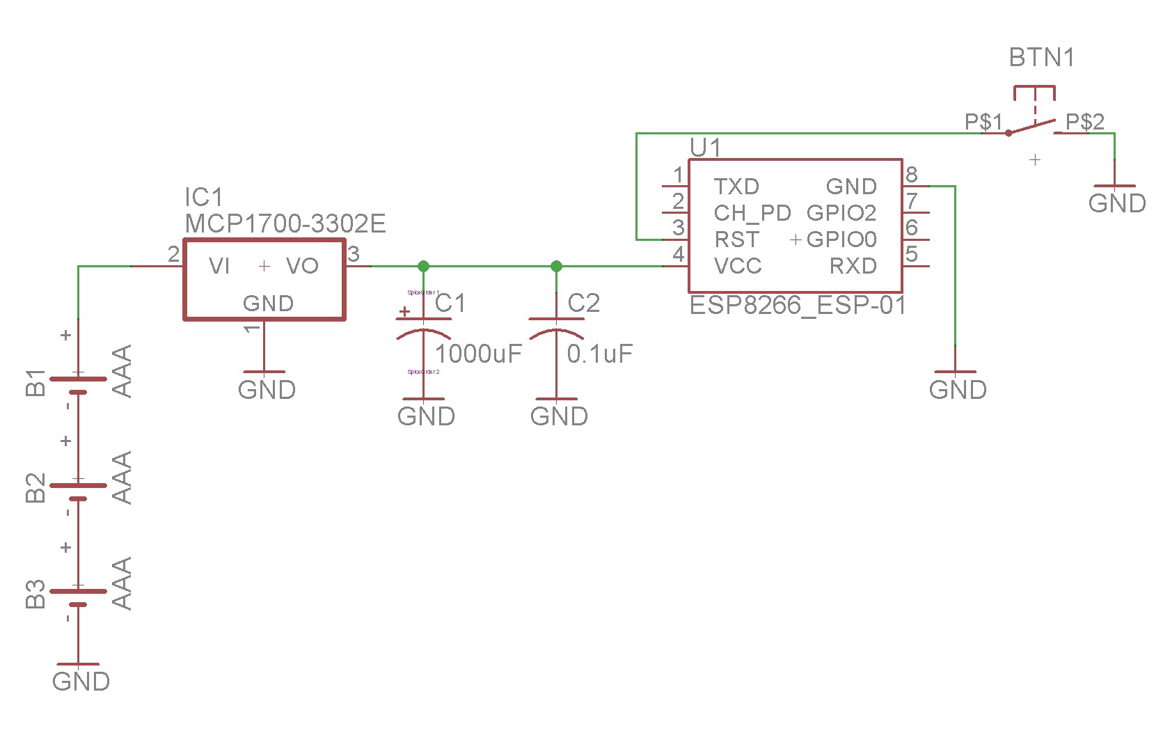
Note that the 1000uF capacitor is perhaps a bit overkill — the datasheet calls for 1uF, which may well be sufficient. I grabbed something random from the junk box without really thinking about it, and also grabbed something I felt would smooth out any high current spikes from the module while it’s performing its RF operations.
The MCP1700-3302E is a low-dropout regulator that has a low quiescent current. Checking the circuit while in deepsleep using my EEVBLOG uCurrent Gold showed the approximately 20-25 microamps consumed.
Implementation
Here are some pictures of the build…
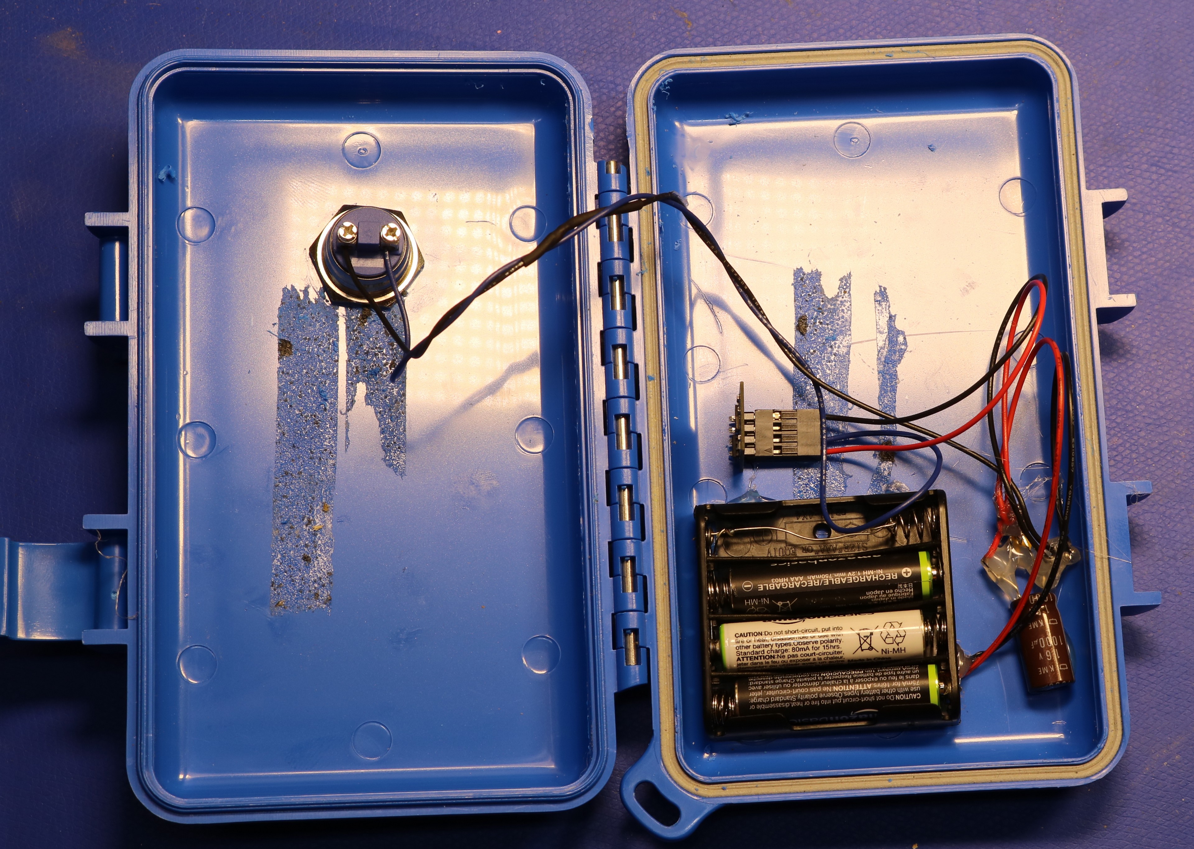
No custom pcboards here. I assembled the regulator and it’s capacitors by soldering the components and wires together. Then I gunked them up good with the hot melt glue gun. The battery holder came from amazon — it’s a quad AAA holder with one of the slots wired across. The button also came from Amazon, the result of a search for “waterproof button” (which I’m not entirely convinced is waterproof; we’ll see). The blue case is an “S3 T2000 Watertight Case”, which I’ve used in a few previous projects.
Resources
Here are some resources useful to the project:
- My github repository, contains source code