In this video, I make a clone of the ET-3404 6809 adapter:
Purpose
I’ve become somewhat of a Heathkit ET-3400 enthusiast lately, after building my ETA-3400 memory/io clone. I decided to also clone the ET-3404, which is a 6809 adapter board for the ET-3400. Why? Simply for completeness sake.
The official “experiments” for the ET-3404 aren’t all that exciting, they’re mostly focused around understanding the differences in the microprocessor. Differences such as addressing modes, register changes, etc. There’s not much flashy interfacing like you would find in the other labs. Nevertheless, the ET-3404 fit an important niche in history. Recall that back in the day all of this stuff was new, computers were expensive, and the ability to upgrade your trainer and learn about the 6809 would have been valuable.
Design
I pretty much used the original design of the ET-3404 and made a few relatively straightforward changes to it, to pick a different ROM and to allow some additional flexibility. The schematic is shown below:
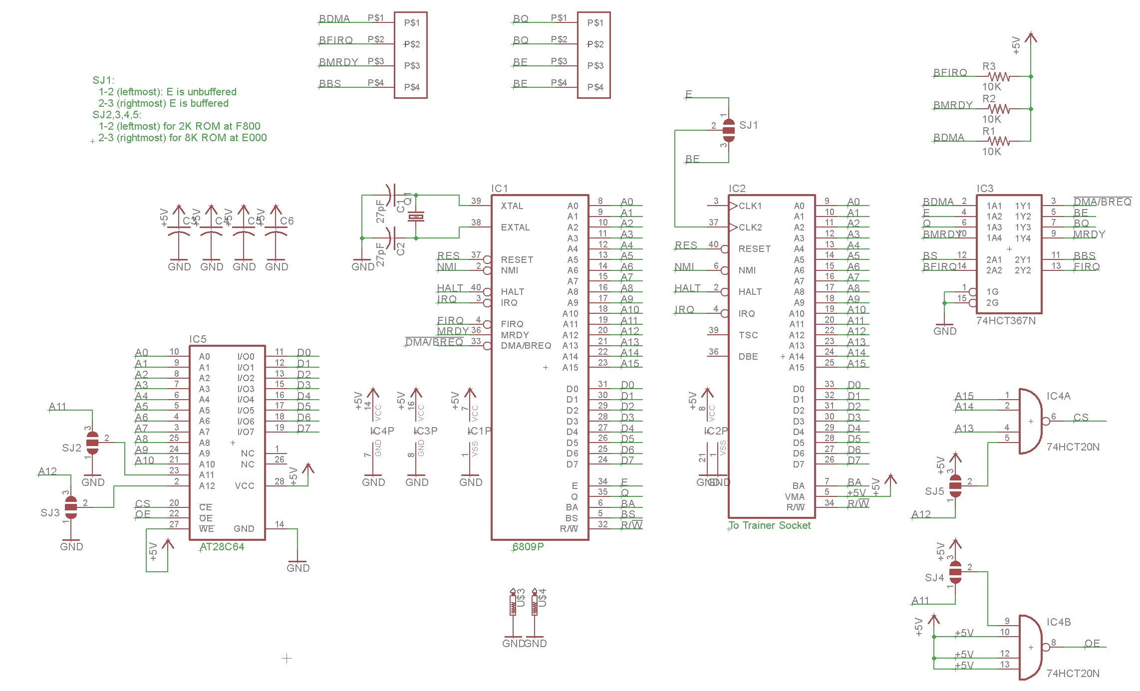
As you can see, I chose to use an AT28C64 EEPROM instead of whatever the original board used. The AT28C64 is popular, easy to program and erase, and I use them in other projects.
The AT28C64 is a larger ROM than the original, so I included some solder jumpers to change around the address lines so that additional space could be addressed. I have not tested this capability — I set the jumpers as described in the schematic to address only 2K of the ROM.
I also included a jumper to select whether the E line is unbuffered. I found two different variants of the original ET3404 schematic, one buffered and one buffered. I’m not sure if one variant is more “right” than the other, but I allowed the option to be chosen by the builder.
Implementation
The completed board is shown below:
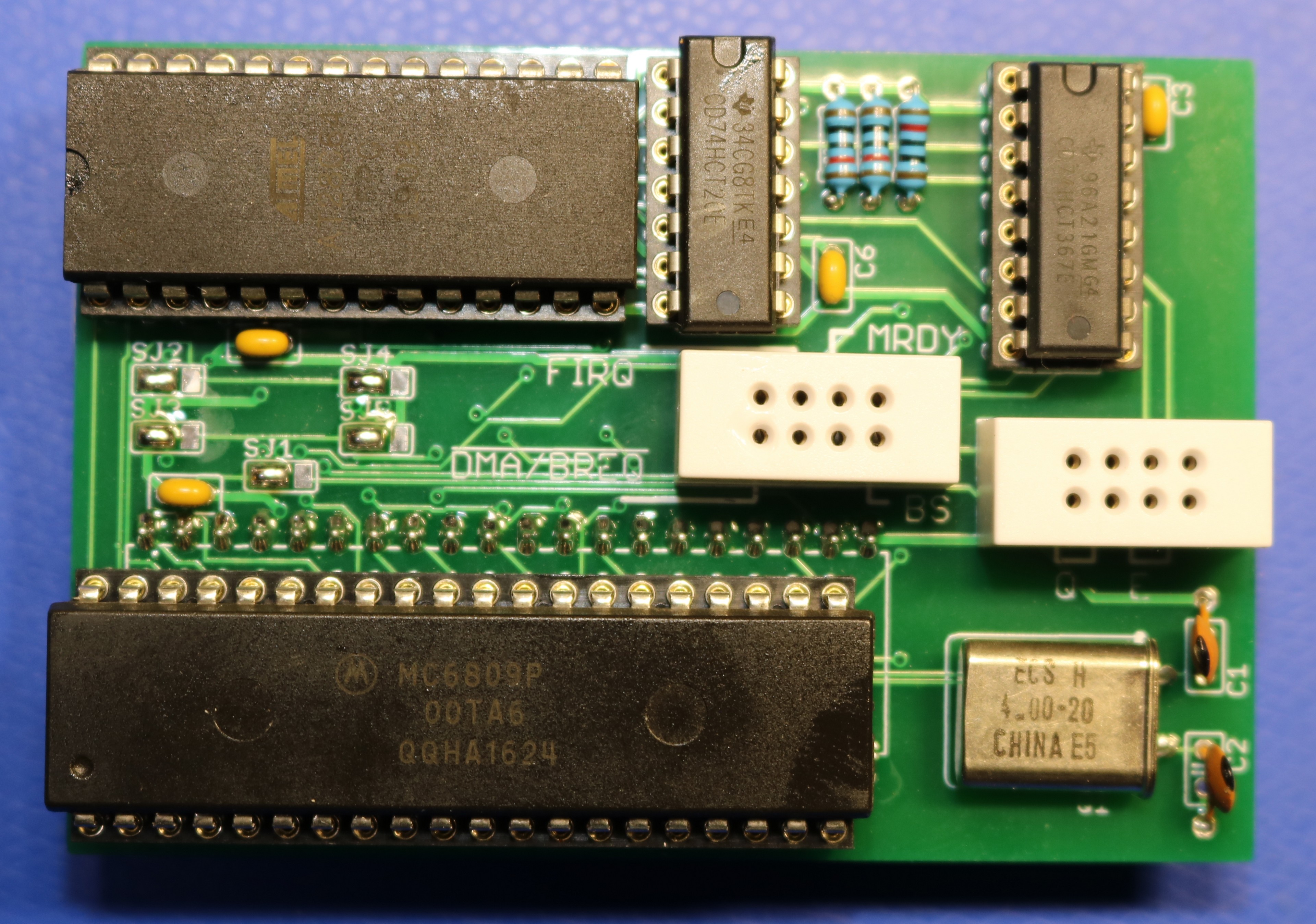
The board design is straightforward. Please note the positions of the five solder jumpers, which are all the way to the left. This is the standard configuration to address 2K of the EEPROM.
The two terminal blocks came from adafruit. If you can’t find them at Adafruit (they were out of stock when I needed them), you might be able to find a supplier such as Mouser or Digikey that sells Adafruit products.
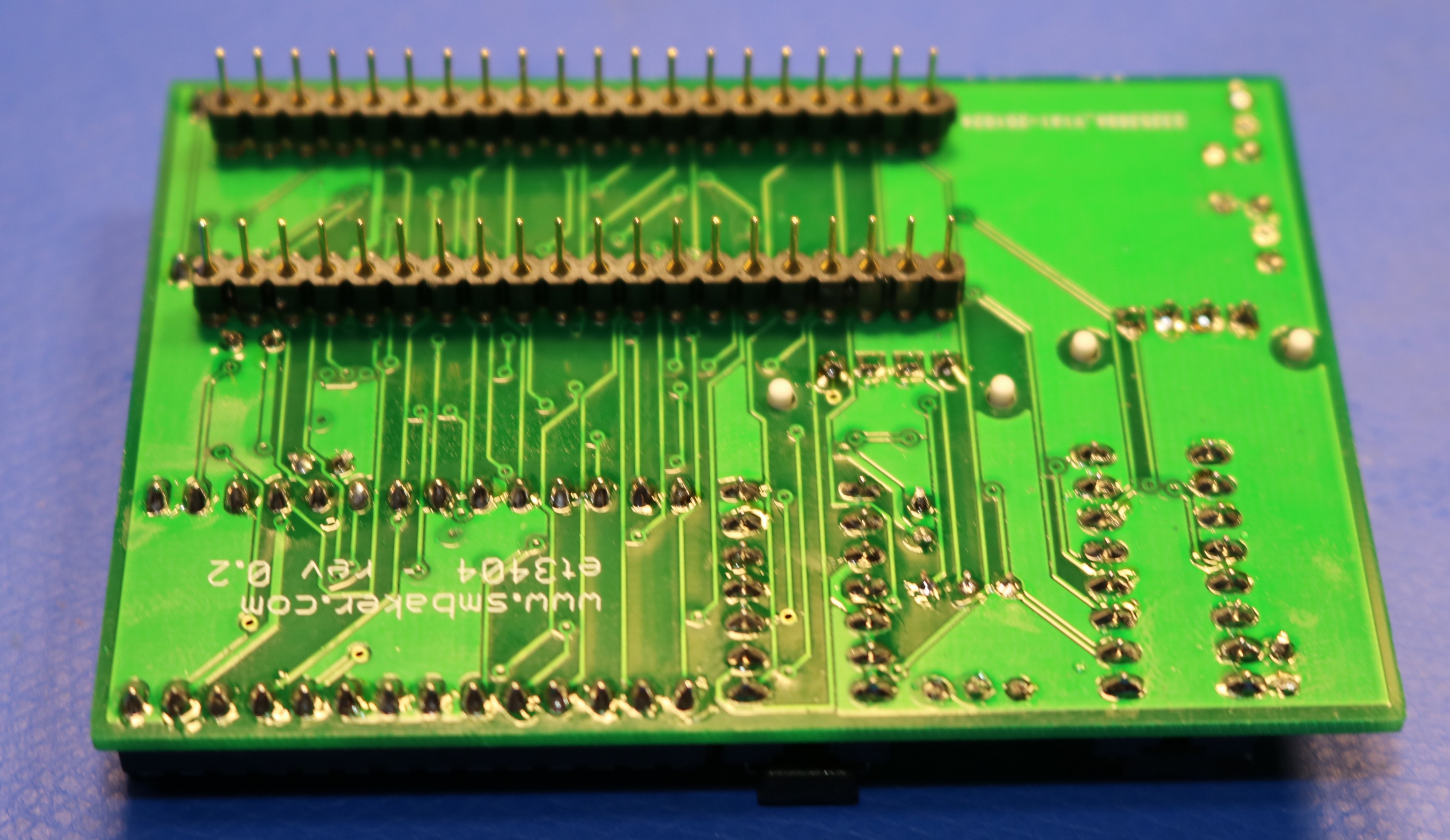
The pins sticking out the bottom of the board are a little hard to source — I found them on ebay. They are *NOT* standard 0.100 header pins, which would be too large to plug into a socket. They are special machine turned pins.
If you’re modifying an ET-3400 (not ET-3400-A)
Heathkit produced two generations of the trainer, the ET-3400 and the ET-3400-A. The 6809 board is a drop-in replacement for the CPU on the newer version, the ET-3400-A trainer. However it is not so simple on the older version the ET-3400.
The ET-3400 requires that you replace the clock driver IC with a small header that includes a resistor and capacitor. This unfortunately requires you to disassemble the ET-3400, including removing the main pcboard from the top shell of the case, as the clock driver chip is not accessible externally. It’s a bit of a pain, doubly-so as once you tire of the 6809 and want to return your trainer back to the 6800, you have to disassemble it again and re-insert the original clock chip.
Bill of Materials
| Id | Qty | Description | Source |
| IC1 | 1 | MC6809P Microprocessor | eBay (see note) |
| IC2 | 1 | set of machine-turned pins | eBay |
| IC3 | 1 | 74HCT367N | digikey |
| IC4 | 1 | 74HCT20N | digikey |
| IC5 | 1 | AT28C64 EEPROM | digikey |
| C1,C2 | 2 | 27pF ceramic capacitor | digikey |
| C3-C6 | 4 | 0.1uF ceramic capacitor | digikey |
| R1-R3 | 3 | 10K Resistor | digikey |
| U$1,U$2 | 2 | 2×4 breadboard socket | adafruit |
| Q1 | 1 | 4Mhz Crystal | eBay |
| S1 | 1 | 40-pin IC socket | digikey |
| S3 | 1 | 14-pin IC socket | digikey |
| S4 | 1 | 16-pin IC socket | digikey |
| S5 | 1 | 28-pin wide IC socket | digikey |
Note: It is important that you get the 6809P, and not the 6809 or 6809E. The “P” includes the built-in clock generator logic. I had numerous problems with either counterfeit or failed 6809P processors. See the following section.
Bad 6809P ICs
One US supplier 2/2 ICs that I received were bad. One China supplier, 2/8 ICs that I bought were bad. This is a significant prevalence of bad ICs and it existed across suppliers from different geographic regions. I’ve spoken with other ET-3400 enthusiasts and they reported similar experiences of receiving many bad 6809P.
The symptoms of the “bad” IC were that it did not generate E or Q clock pulses. There doesn’t seem to be a better way to evaluate them other than to buy several and try them in-circuit.
Interestingly, I did try to force clock signals into these “bad” ICs, similar to how the 6809E (the variant without an internal clock generator) is supposed to be used. I found that with an external signal generator, it was possible to get these ICs to function. The weirdness then is that 6809P are behaving like 6809E. Given that the problem happened from multiple suppliers with different lots of ICs, I’m skeptical that it’s a simple counterfeit. My pet theory is that there is an internal fuse or other feature that differentiates a 6809P (with clock generator) from a 6809E (without clock generator) and that fuse has degraded over time. That’s just speculation though.
The bottom line is that obtaining a functional 6809P may be a challenge for this project, and if you don’t have a source of known-good 6809P then it may be difficult to ascertain whether a failed board is due to a bad IC or a different problem. The telltail check is to put a scope on the E and Q outputs and see if they’re dead or alive.
This current sensor can easily be used for measuring currents up to 15 Amps constant and can even handle about 20 Amps peak. I had previously built a shunt current measurement module using a home made shunt but it had a few limitations- The wire was quite long which may not be suitable for small devices. It also got rusted over time and one major drawback was heating at higher currents even at 10 amperes. Well, this module solves almost all of these problems in a more efficient design.
Just thought I’d clarify that the “P” suffix (MC6809P), simply identifies the Plastic package DIP. Likewise, “L” suffix is the Ceramic package, and “S” is the Cerdip.
So, the MC6809P, MC6809L, and the MC6809S, are all the same MC6809, just in different DIP packaging.
The different one is the MC6809E.
Your note: “… not the 6809 or 6809E”, is therefore a bit misleading.
Also, as many China sources annoyingly re-label recovered IC’s, it is common with devices like memory IC’s that devices are laser relabelled with incorrect speed ratings etc.
In the case of a MC6809 CPU, I can see that they could easily be mislabelling any plastic packaged MC6809 (including a MC6809E), with just a generic “MC6809P” label, without realising the significance of the “E” suffix.
This would most likely explain your “incorrectly” operating MC6809P’s. 🙂
Hi Scott,
It appears that a 2764 EPROM will work too, correct?
Also I could not find any details (schematic) of the clock header mod for the ET3400. Please point me to that.
Thanks!! Mike in Anchorage.
I configured this board with the jumpers set to addressing the full 8 k address space (shorting positions 2-3 for SJ2, SJ3, SJ4, and SJ5. The device works properly. Of note is that the 2K-sized 3404 ROM image needs to be burned into ROM location offset 0x1800 when using the full 8K address space. This has the effect of placing the image at 0xF800, as it should be. It also allows for user programs to be placed in locations 0xE000-0xF7FF, representing the first 6K of the 2764’s overall 8K of memory space.