In this set of videos, I work on getting a used Convergent Technologies NGEN computer up and working:
In the second video, I figure out the pinout for the 25-pin connector, and I get the keyboard working and the video displayed on an MCE2VGA.
In the third video of the series, I design and build a breakout board that implements the keyboard/video breakout that I described in the second video. I also install the CTOS operating system, and spend some time trying out operating system features.
For part four, I go through a set of unique Convergent modules that were donated to me by a viewer, Joe. These include 286 and 386 CPUs, SCSI disk drives, a QIC tape module, even an Ethernet module. Joe was also kind enough to send along some real convergent Monitors, so I no longer need to use my breakout board.
Why?
I briefly encountered a few of these Convergent Technologies / Burroughs units back in the 1980s, and I wanted to have one to play with. I had been watching eBay for a while, and when some reasonably priced ones showed up, I decided it was time to acquire one and get it going.
History
Convergent Technologies was a computer manufacturer back in the 1980s, eventually bought out by Unisys. The company produced several different computers over its lifespan, the IWS, AWS, NGEN, and a few mainframe-like computers called the Miniframe and Mightyframe. These machines were marketed by Burroughs at the time, so you might come across these workstations marketed as the Burroughs B20 or B21 (AWS), or the B25 (NGEN).
One thing that separates out the Convergent Technologies NGEN computers from other offerings at the time was the modular design. As shown in the video at the top of the page, the computer is designed based on several different modules that are coupled together electrically by a large header, and mechanically by a latching mechanism. The computer I purchased consisted of a CPU module (CPU, RAM, IO, Video) and a storage module (HDD, FDD). Other modules available at the time would have been dual floppy storage modules, a color graphics module, and disk expansion modules.
Power
Each module is powered by 36 volts DC, and includes one or more built-in DC/DC converters that convert the 36V down to something more useful, such as 12V or 5V. The 36V is distributed from one module to another via the header connectors that couple modules together.
The 36V power is sourced from one or more external power bricks. The bricks connect to the modules using 8-pin SDL connectors. You can power multiple modules from a single power brick if the combined power consumption of the modules is less than the amount of power provided by the bricks. Each module typically has a power requirement printed on the back. For example my CPU module is a 4 and my FDD/HDD module is a 6. This adds up to 10. The single power brick I have is also a 10, so we can power the whole computer from one power brick.
Here is the pinout for the power connector:
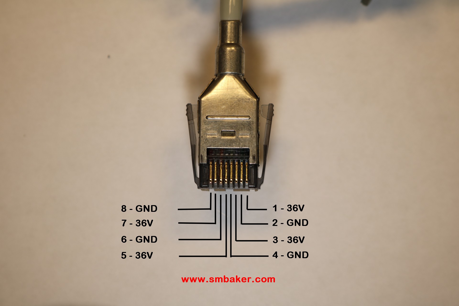
Note that I’ve shown the SDL connector pin-side-up. Beware that if you’ve lost your power cable, you cannot substitute a keyboard cable for a power cable even though they are both SDL cables. 1) They are keyed differently and will not physically plug in, and 2) The keyboard cable has pins 2 and 7 swapped.
Remember that time the power brick caught on fire?
Yes, the power brick caught on fire, we’ll get to that in a moment. In the meantime, here is a picture of the power brick:
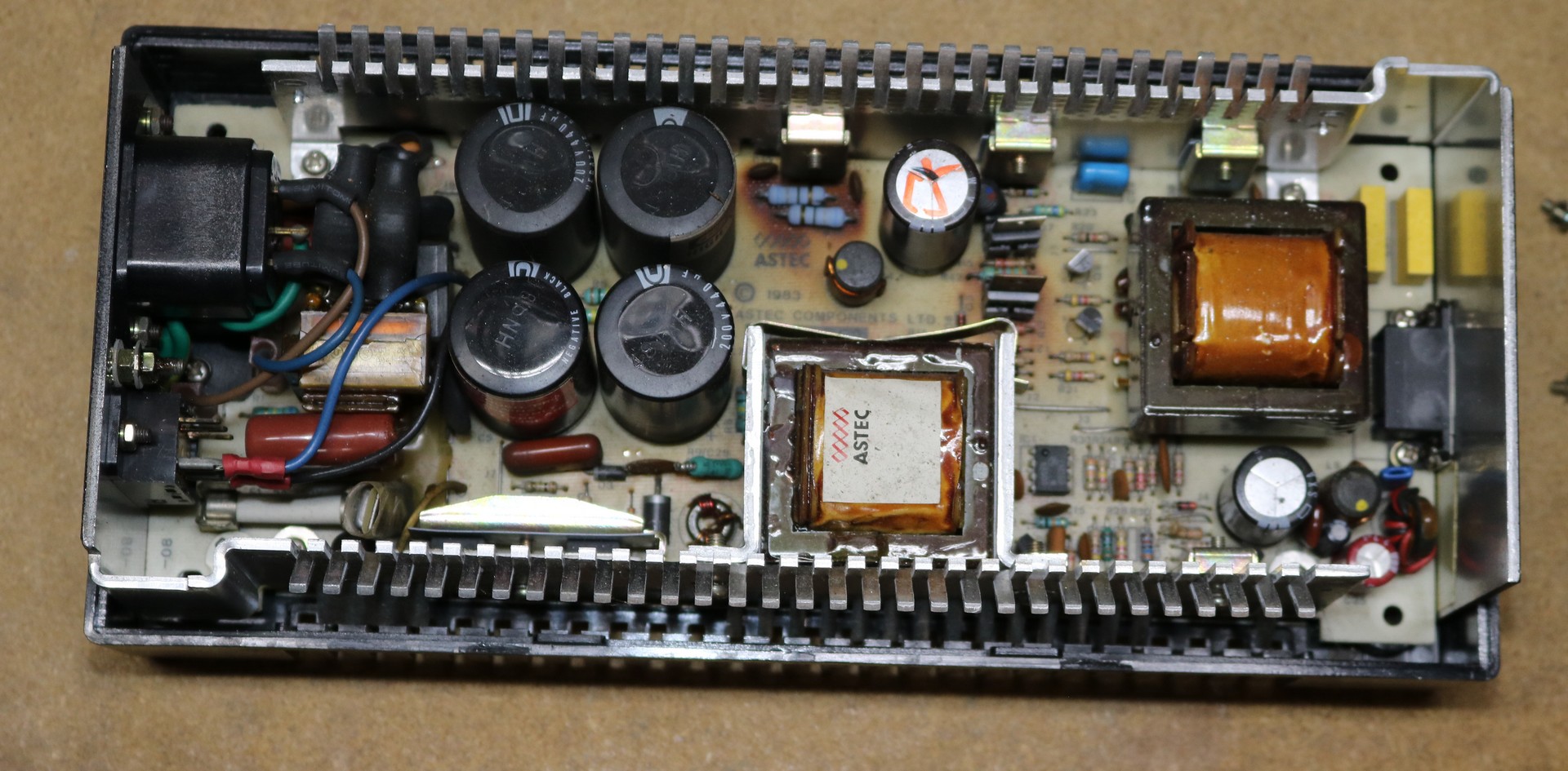
The power supply is made by astec. It’s full of lots of beefy transformers, transistors, diodes, and a couple massive heatsinks.
Notice the small white/yellow rectangular part under some wires between four large capacitors and the AC jack on the left. About 10 minutes into my first run of the power supply, it did this.
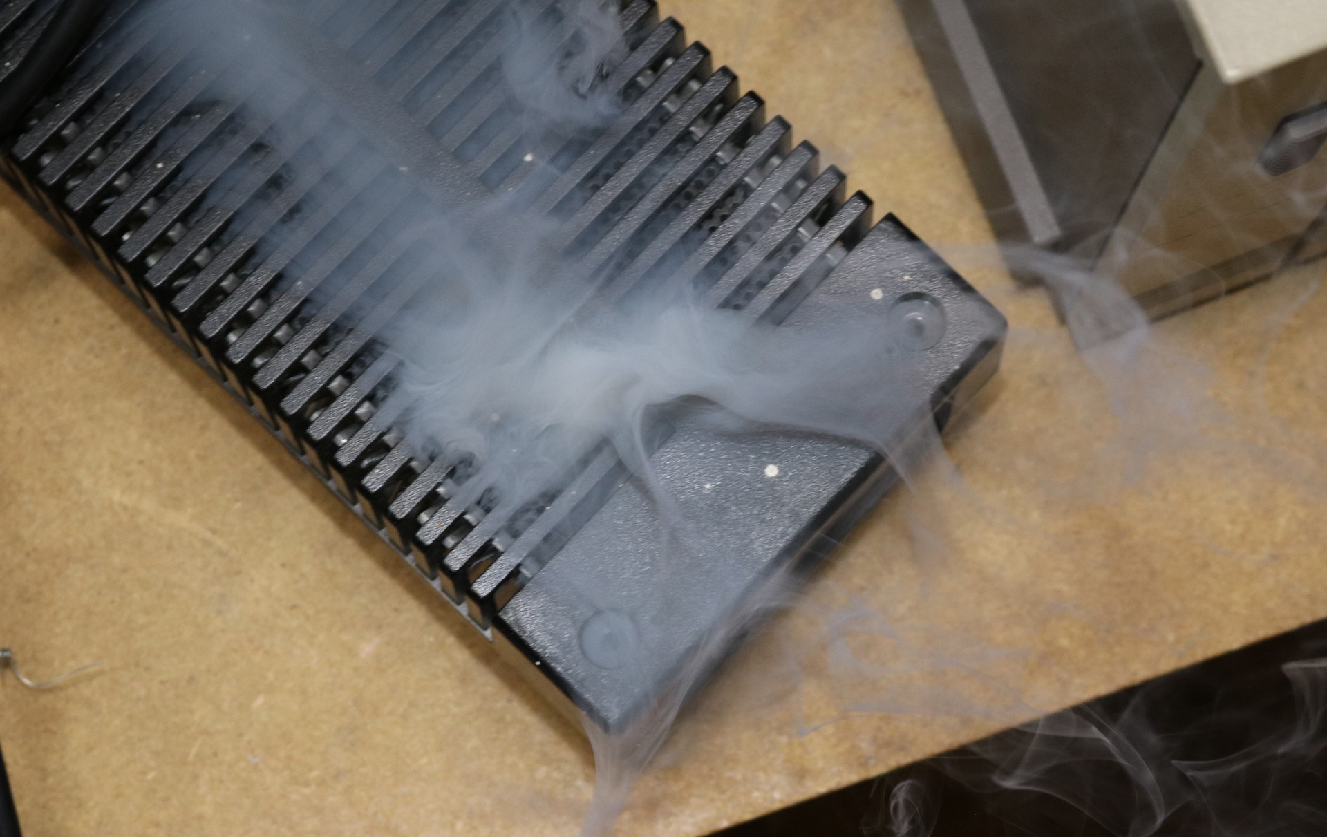
The above picture is a minute after the initial combustion, I didn’t have the camera setup. There really wasn’t a whole lot of fire, just a little bit, but quite a lot of smoke and the office stunk for a day or so. The culprit was an “X2 Safety Capacitor”. These caps go between the line and neutral and are used to reduce AC line interference. Caps from the 1980s are notorious for undergoing spontaneous combustion. Fortunately the rest of the supply was not damaged and it continued to work fine once the cap was removed. It’s not critical, but I’ll make a note to replace it.
Keyboard
At first it looks like your typical PC keyboard, but it’s really quite a bit different. The keyboard has LEDs on some of the function keys. It uses SDL connectors, similar to the ones used by the power cable. The pinout is nothing like a PC connector.
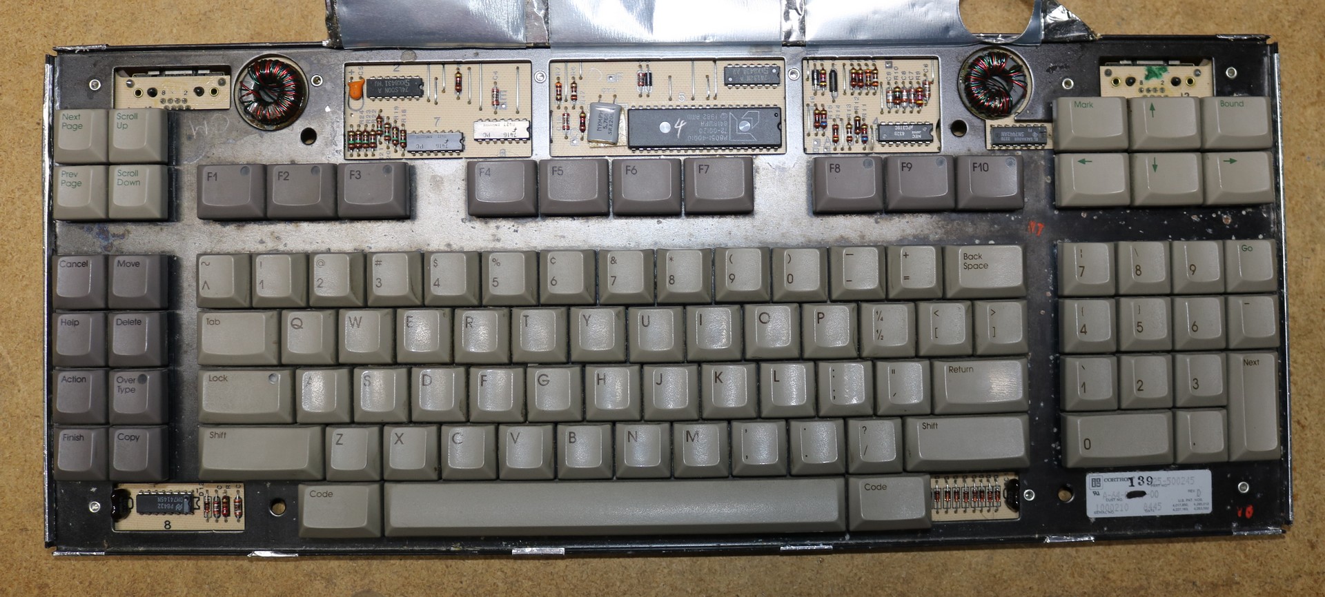
The CPU in the keyboard is an 8051. The interface communicates to the computer with three IO lines: Reset, Data_In, and Data_Out.
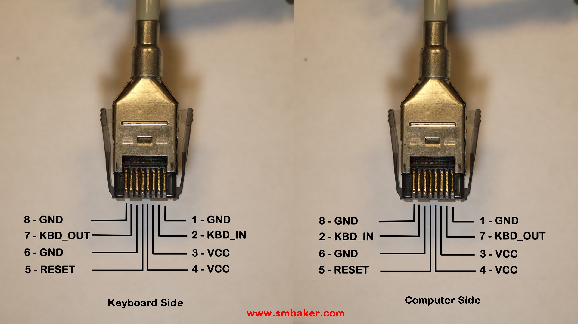
Here is the pinout of the keyboard cable:
Video
My CPU module included a monochrome video board. The problem is, this video is output through a DB25 connector on the IO Board, and there is no known pinout for this video connector. The NGEN series has a special purpose-built monitor that connects via the DB25. The keyboard signals are routed through the DB25, and broken out on an SDL connector on the monitor. As of today while I’m writing this, the schematic for the monitor and the schematic for the IO Board and Video Board are unknown to the Internet, so there’s no obvious source to get the data other than experimentation.
I started by pulling the IO Board, so that I could trace what wires connected to the monitor DB25.
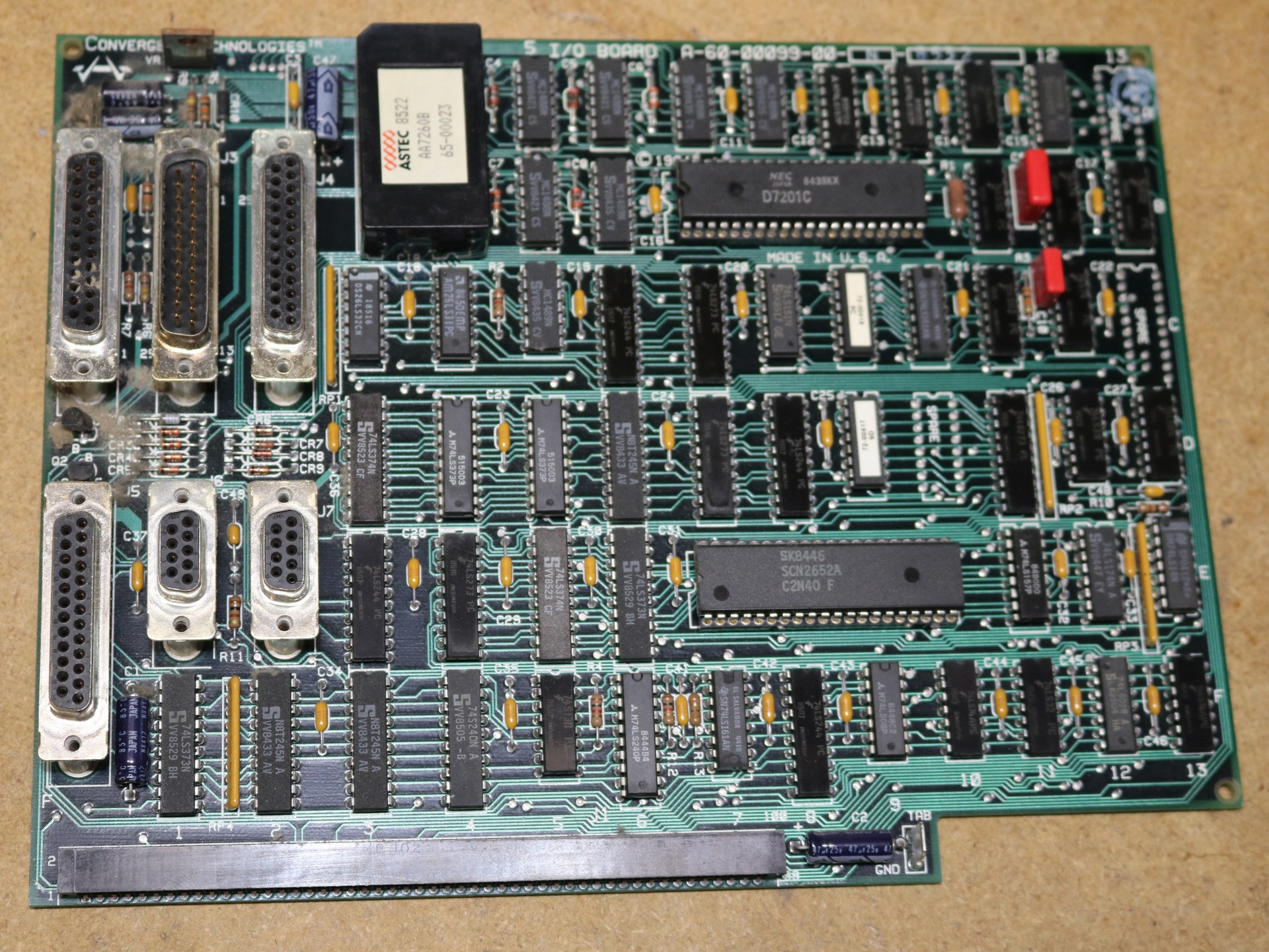
Here’s what I found by examining all 25 pins of the monitor connector:
| Signal | Pin | Pin | Signal | |
| EC-67 SPEAKER | 1 | 25 | NC (35 VDC from LM317) | |
| EC-29 PWR_ON (Low) | 2 | 24 | G | |
| ? | 3 | 23 | Enable LM317 | |
| EC-32 Monitor_Detect | 4 | 22 | EC-94 – out to kbd | |
| G | 5 | 21 | EC-93 – in from kbd | |
| G | 6 | 20 | G | |
| OUT (74S240N-??) VIDEO | 7 | 19 | G | |
| OUT (74S240N-16) INTEN | 8 | 18 | OUT (74S240N-14) VSYNC | |
| G | 9 | 17 | OUT (74S240N-18) HSYNC | |
| G | 10 | 16 | NC (G) | |
| G | 11 | 15 | NC (G) | |
| 35 VDC from LM317 | 12 | 14 | EC-10 – kbd reset | |
| NC (35 VDC from LM317) | 13 |
Note 1: On the DB25, pin25 is next to pin13 — the breakout board I used kinda flips the rightmost column.
Note 2: Pins 12, 13, and 25 were connected on my CP-001 80186 unit, but documentation leads me to believe that 13 and 25 may be unconnected on a color graphics adapter. This is unconfirmed. My first version of the breakout board has all three pins connected.
Note 3: Pins 15 and 16 were connected to GND in my CP-001 80186 computer, but documentation leads me to believe they are connected to signals on a color graphics adapter. May be best to leave them not connected.
Several of the pins (5, 6, 9, 10, 11, 15, 16, 19, 20, 24) are grounds. This is not unusual. Having many grounds allows them to put power returns separate from signal returns and to give some signals isolated returns. It’s possible that the factory cables might have used twisted pair or coax on the video signals, for example.
Pins 12, 13, and 25 provide some voltage from an LM317 voltage regulator on the IO Board. These pins have approximately 35 VDC on them when enabled. The LM317 appears to be enabled by placing a low signal on pin 23. This could be the monitor’s way of signalling to the PC that it is connect ed and that power should be supplied.
Pins 7, 8, 17, and 18 are all connected to a 74S240N gate on the ioboard. My original hypothesis was that these were for the keyboard circuit, but I can confirm that at least three of them are video! Pin 18 is the Vertical Sync at 60 Hz, ping 17 is the Horizontal Sync at approximately 22 Khz, and pin 7 is Video Out. Pin 8 is Intensity. There is a 19.980 Mhz crystal on the video board, and my hypothesis is that the video bitclock is 19.980 Mhz.
A total of six pins go out to the edge connector on the IO board. Of those, four of them I was able to trace to the edge connector on the video board:
| IO Pin | Video Pin | Notes |
| EC-32 | EC-32 | Input to a 74LS240 pin 2 (D1) and 74LS74 pin 11 (B12), 1K pullup |
| EC-67 | EC-67 | Output from 74LS38 pin 3 (F7) |
| EC-93 | EC-93 | Present on video board edge connector, but unable to trace on video board |
| EC-94 | EC-97 | Present on video board edge connector, but unable to trace on video board |
The video board’s EC-93 and EC-97 pins I was unable to trace to any component on the video board.
Pin 1 is a logic-level audio output. You can use this together with appropriate resistors and a PNP transistor to drive a speaker and the computer will beep as appropriate.
Pin 2 appears to be a power_on signal. It is active low, and pulls itself up to around 4V when inactive.
Pin 4 is used to detect the monitor. If this pin is left floating then some weird things will happen — B25 diagnostics does not have video tests but does show a dual-drive unit that didn’t exist, for example. Some versions of CTOS either would not install or would not work. I think the OS either turns off the video if it thinks the monitor is not present, or it simply misbehaves. Connect this pin to ground to signify that a monochrome monitor is present. For other monitors (color, VGA, ??) then I’m not sure exactly what you should connect this pin to.
Viewing on a VGA Monitor
I used an MCE2VGA (https://sites.google.com/site/tandycocoloco/mda-cga-ega-to-vga), which is a small board that converts digital monochrome video to analog vga. It deals with all the grief about converting different refresh rates and different resolutions to something a vga monitor can deal with. In it’s native form, it can handle IBM PC MDA (monochrome), CGA, and EGA.
However, the convergent video output is not the same as IBM PC MDA, so I had to make a few changes:
- I modified the MCE2VGA dot clock to be 19.980 Mhz instead of 16.257 Mhz
- I modified the MCE2VGA monochrome vertical sync to be positive instead of negative
- I disabled the MCE2VGA’s CGA and EGA modes
My custom fork of MCE2VGA is available at https://github.com/sbelectronics/mce2vga-convergent-technologies
Viewing on an IBM-5151 Monochrome Monitor
If an MCE2VGA and a modern flat panel isn’t really your thing, but you don’t have access to a convergent monitor, then you can get the machine to work with something like an IBM 5151 monitor.
Note that the dot clock and refresh rates of an IBM MDA are different from the convergent’s native output, and connecting a 5151 as-is will likely damage the 5151 monitor. You’ll need to do two things to get it to work right:
- Change the crystal on the Convergent’s video board from 19.980 to 16.257.
- Invert the video sync pulse, for example with a 74xx04 hex inverter.
In my third video linked at the top of this blog post, I do exactly these steps, and get some video output on my trusty 5151. It sure is better viewing a vintage PC on a green monochrome CRT than on a modern LCD. It just doesn’t feel the same on the LCD.
Connecting the Keyboard
Combining the tables above, we can establish an interconnect for the keyboard and monitor connectors:
| DB-25 | KBD | Signal Name |
| n/a | 3, 4 | +5V |
| 14 | 5 | Reset Keyboard |
| 20 | 1, 6, 8 | GND |
| 21 | 7 * | Serial – Keyboard to Computer |
| 22 | 2 * | Serial – Computer to Keyboard |
* Important Note: the KBD pins above are on the connector on the keyboard. Keep in mind that the standard coiled keyboard cable swaps pins 2 and 7. If you’re making your own cable, use the pin numbers I specified above. If you’re using the coiled convergent keyboard cable, then make sure to swap these two pins. Refer to the picture further up in the document that shows both ends of the keyboard cable if you have any question.
There is no +5V source on the DB-25. In my prototype I used an external wall wart to power the keyboard. When I make a final board, my plan is to use a switching regulator to step the 35 VDC on pins 12/13/25 down to 5V.
Using a PS2 Keyboard with the Convergent NGEN
Convergent keyboards are few and far between, and the one I own is starting to get really funky with some of the keys being intermittent, so I decided I would build a converter to use a PS2 keyboard. Fortunately, Joe had donated me one of his development workstations, and it included some documentation on the Convergent I-BUS, and on the design of one of the Convergent keyboards. This described not only the IBUS protocol, but even the scancodes used by the keyboard. The only thing that wasn’t clear to me was the reset timing, so I took a few scans with the oscilloscope.
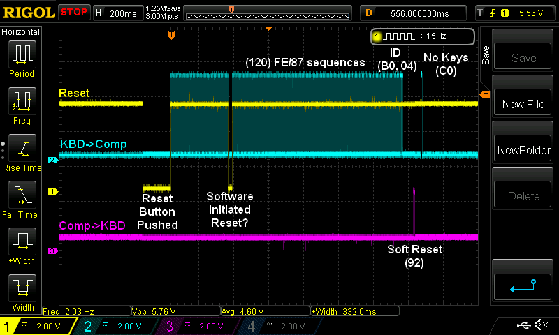
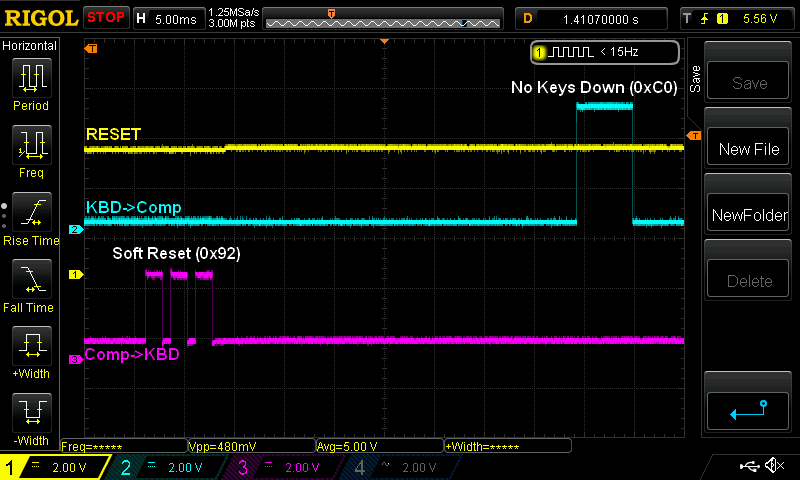
As you can see above, on the low-to-high transition of RESET, the keyboard sends a sequence of 120 alternating FE and 87 bytes (NOTE: Official documentation only mentions the FE bytes, but the 87s are observed in the keyboard diagnostics). After the FE/87 sequence the keyboard sends an id of B0 and 04. The B0 identifies it as a dual-ported keyboard, and the 04 identifies the layout as a US K1 keyboard . Then the keyboard sleeps until it receives a soft reset (0x92) from the computer. That will enable the keyboard’s periodic scan, and the first scan will usually be “all keys up”, which is a 0xC0.
The scanning protocol is fairly simple. The keyboard scans itself periodically and it reports the scancodes of all the keys that are depressed, with the high bit set on the last key that is pressed during the scan. If no keys are pressed, it reports C0. There’s no specific “key up” sequence like there is on a PS2 keyboard — when you release a key, the next scan simply won’t list that key as being down.
I built a couple prototypes of a PS2-Convergent converter. The first was based on an ATTINY85, which was a bit problematic due to the lack of a real UART. I won’t say much more about that prototype, as I immediately designed a second one that used an ATMEGA328. The 328 has a real UART, and many more GPIO pins. Below is the schematic of my keyboard converter:
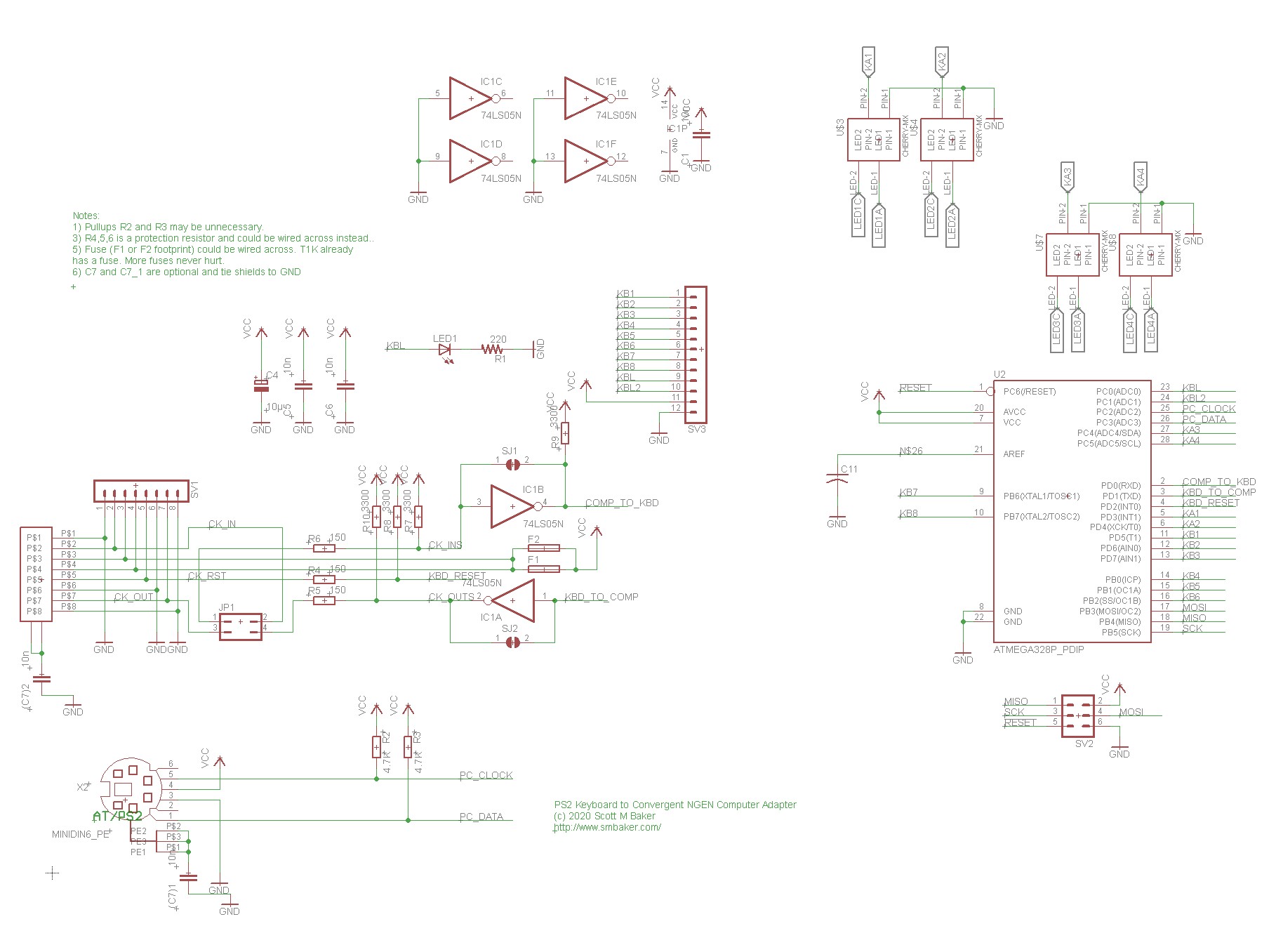
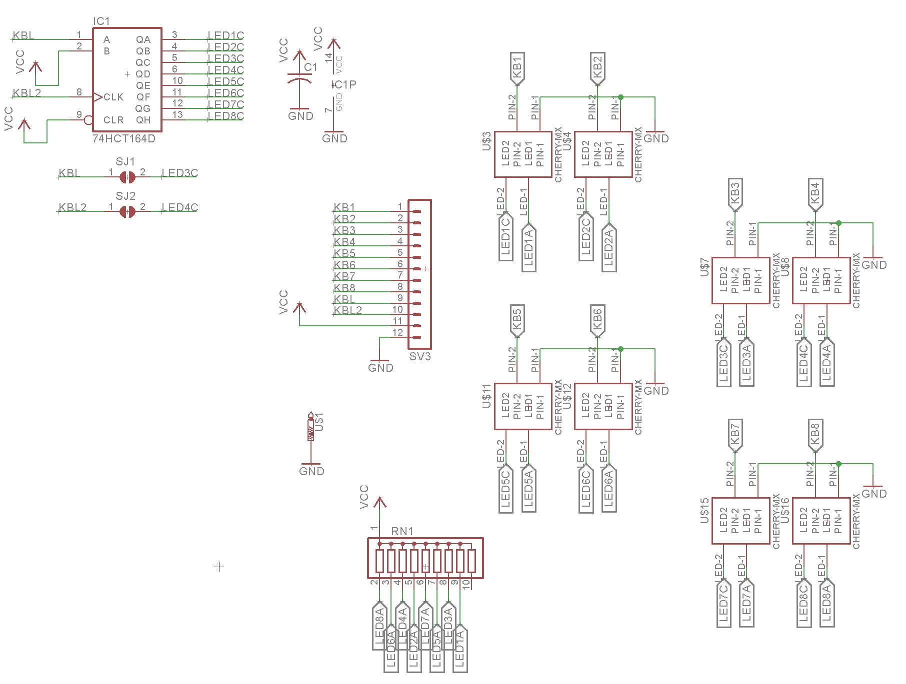
The serial logic on the Convergent side of things is inverted, so there’s a 74HC05 hex inverter on the serial lines from the ATMEGA328 to the convergent PC. The PS2 connector is bit-banged from the ATMEGA328. That’s really all there is to it.
I had a bunch of spare GPIO on the 328, so I added support for 12 optional keys that could be direct-wired to the 328. You can build the converter with or without these optional keys. If you build without, then all of the “special” convergent keys (help, scroll up/down, cancel, finish, etc) can be emulated with a 104 key PC keyboard. If you build the converter with the optional 12 keys, then you can have a dedicated keypad for those special convergent keys. It’s really nice to have the dedicated keys, rather than rely on wacky remapping of a PC keyboard.
Below is a picture of the completed adapter sitting next to my old dirty compact PS2 keyboard:
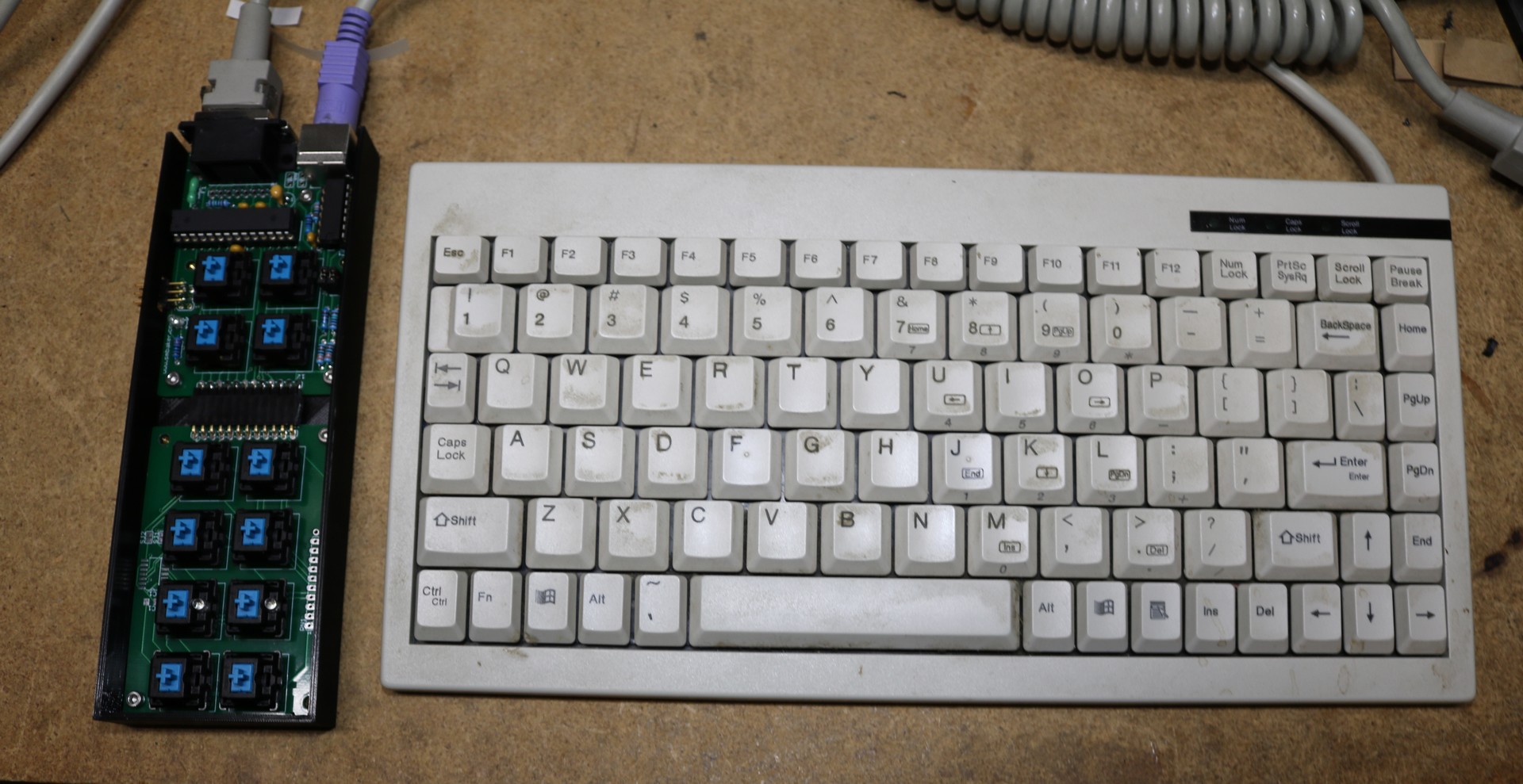
The code and the schematics for the keyboard adapter are available on my github repository at https://github.com/sbelectronics/convergent-kbd.
Convergent DC-DC Converter
As shown in the videos, each Convergent module typically has one or two DC-DC converters. For some modules, the CP-001 CPU module, for example, there are two 5V converters. Other modules, such as the HDD/FDD may have one 5V and one 12V. I did take the time to map out the pins on these modules.
| Pin | Signal |
| 1 | V-IN, 36V |
| 2 | GND-IN, also connected to system GND in CPU module |
| 3 | V-OUT |
| 4 | V-OUT |
| 5 | V-OUT |
| 6 | V-OUT |
| 7 | V-OUT |
| 8 | Leave floating and module will output 5V. Pull down to GND and module will output 12V. |
| 9 | GND |
| 10 | GND |
| 11 | GND |
| 12 | GND |
| 13 | GND |
| 13 | Unknown (see note) |
| 14 | Enable — pull to GND to enable module |
Pin 13 I’m not sure about. The CPU module shows a 1K resistance between this pin and GND. When the module is turned off, I measure about 0.6V. When the module is turned on, I measure about 2.4V. Unsure of the function on this pin.
LOVED reading this post and watching your video! I worked for Burroughs in the early 80s, and another company after that used the B20 series. I had a B26 for some years that I used to support customers when working from home. I wish I hadn’t sold it. Good luck getting yours running again. The B20 series and BTOS were way ahead of their time and were a great platform. Mine was 386 based (B26, if I remember correctly) , had a whopping 20 Meg hard drive, expanded memory (another whopping 256k), a floppy drive, a tape drive and used 4 power supplies.
I look forward to your next video / post.
Hey! I worked on that keyboard serial protocol, back in my Convergent days. It daisy chained devices. It sent its own bytes to the output (keyboard, mouse, card scanner, whatever). Anything on its input side, it sent to the output with an ‘esc’ character (I forget what that was). The OS counted escapes preceeding each packet, to know what device sent it. 1200 baud, not to fast.
My father was a Burroughs tech and worked on them, my first computer was a B21-4 and used it for college courses and business. I could connect to university main frame from home.
I would really like to resurrect this OS to compete in today’s world.
THANK YOU!
I’ve been nostalgic for the B25 cluster systems I managed in the US Coast Guard in the late ’80s. In this age of commodity lowest-common-denominator systems that squander our energy on way over powered consumption streaming devices. Though, today we could deliver B25 cluster system functionality on much more efficient devices.
Holy mackerel this was a blast from the past. I worked for a CT reseller and I configured and serviced a lot of Convergent Technologies units. As I recall, the Office of the Commandant of the Coast Guard was all IWS and NGEN systems.
As Mr. Salomon says, CTOS/BTOS was waaay ahead of it’s time, and these units–hardware and software both–were absolutely beautiful.
Thanks for the interesting presentations!
I worked at CT from 1982 until 1989. I was the manager of Applied Systems, which was the ‘specials’ group. My team worked with the various OEMs on special projects that were outside of the normal CT software development cycle.
I loved CTOS and worked on enhancing it by suggesting upgrades that my customers needed.
I eventually became a manager of a software team to build the Generic Printing System and was the customer rep during the Internationalization of CTOS and all of its Standard Software.
The last assignment got me assigned to work at Bull Corporation in Paris over the summer of 1987. My wife and I rented an apartment in the city and leased a small Peugeot for the 3-month assignment. Not bad duty.
Recently, I was given an NGEN 186 with a graphics processor and color monitor. The 40MB hard drive is dead, so I am looking at modern solid-state replacements and will probably go with the BeagleBone offering.
Hi Scott,
I contacted Joe Altmier about locating any CTOS software on diskette media. I am looking for software development tools, like the PL/M and/or Pascal compilers, as well as linkers and library tools. I am using a Gotek device to replace the old floppy drives, so any *.hfe files compatible with the Gotek would be a wonderful find. Do you have a CTOS software library that I could clone onto a Gotek setup?
Ah, memories! I cut my programming teeth on B21 and B28 systems, using Pascal & Cobol 85, ISAM data bases, even developed my own set of “system calls” to mimic GUI’s. I worked for a large Govt department runnin B7800 (later A-series) main frames, had literally hundreds of remote data capture centres on B28s, used ET1100 emulation to batch-transmit to the CP2000 FEPs over poll/select protocols… Did the last update & fix in 2005, some sites ran for 20 years without a hitch! What a machine…
Interesting computer, but using the same connector for the keyboard and power sounds like a disaster waiting to happen.
Great read and video’s! I have two Burroughs B38’s myself, with HDD and floppy, along with monitor and keyboard.
Both MFM hard drives are still working. I wonder what would be the best way to image the hard drives in case these would fail.
Frank, try looking for something called an “MFM Emulator”, designed by David Gesswein. It’s excellent for not only emulating MFM drives, but also imaging existing drives. David sells pcboards which you can build up yourself, but there are also others that offer complete turnkey pre-assembled boards. Would be great to get your drives imaged and preserved!
Hello! Awesome work on adapting this machine. I recently got a 386 machine myself, but just the basic machine itself, I didn’t get the power supply, monitor, or keyboard. I looked at your github, but I didn’t see your breakout board on it at all, Would you be willing to post it or could I buy one from you? I’m planning on making the keyboard adapter too.
Thank you Scott, I ordered the pcboards from David and I will soon build one and image the hard drives in my B38’s.
Hi Scott, I managed to get the MFM Emulator build and I imaged the drive of the known working B38. The drive has a few bad sectors and after installing the original drive back in the case, the B38 is now in a boot loop (FH01 V1.02…….).
I installed the MFM Emulator instead and the emulated drive works, but it is showing the same behavior. After boot looping for over an hour, I have shut down the system.
Do you happen to have a working image which I can use on the MFM Emulator to have the B38 working again?