Welcome to my blog.
Most of my entries these days are about various electronics projects that I’ve designed. All of the electronics project entries can be viewed from the electronics project index. There are also various other categories, including a how-to section and a product review section. If you want to view one of the other categories, then use the ‘Categories’ drop-down to the right.
Now let’s start with the most recent blog entry…
Online RC2014 Emulator!
Try My RC2014 Emulator Online, Right in Your Browser
In this post, I put an RC2014 Z80 computer up on the web so that anyone can tryit out, right from their browser, with nothing to install.
If you’ve followed my channel or my blog, you know I have a soft spot for theRC2014. It’s a lovely little Z80 machine, and it’s the computer that my own operating system, NostOS, was written for. The trouble with hardware is that not everyone has it. I wanted a way for people to get a feel for these machines — to boot NostOS, poke around in CP/M, type a little BASIC — without having to buy a kit and solder it together first. So I wrote an emulator and put it online.
You can try it right now at –> rc2014.smbaker.com <–
How it works
Under the hood, this is built on top of my Go-based Z80 CPU simulator, the same core that I use for developing NostOS. When you connect, the server spins up a private emulated RC2014 just for you, and wires its serial console straight to a terminal in your browser over a WebSocket. What you’re typing goes to an emulated ACIA; what the machine prints comes back to an xterm-like terminal. As far as the ROM is concerned, it’s talking to a serial terminal like it always has.
I run the Z80 at its authentic ~7.4 MHz clock speed, so the emulated machinefeels the way real hardware feels — not artificially sped up. Each visitor gets their own machine, and the machines are completely independent of one another.
Pick your machine
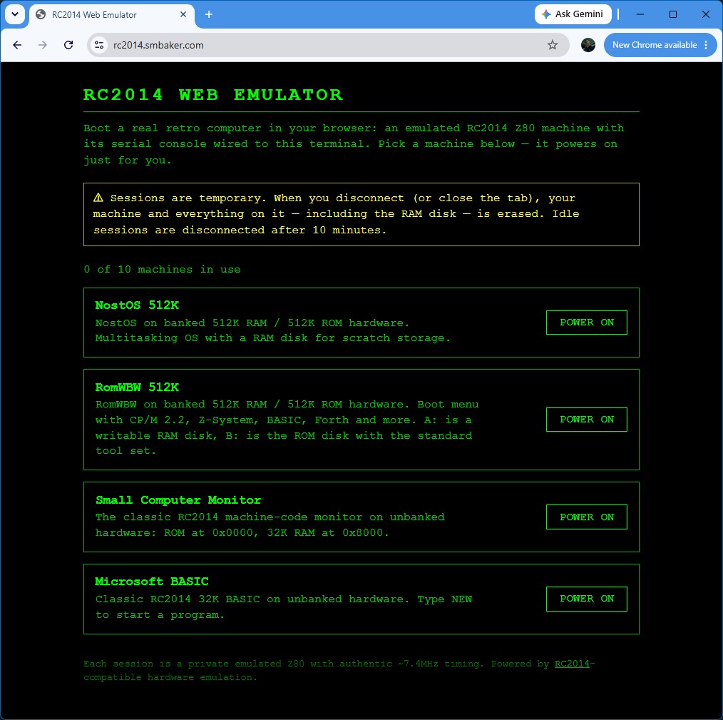
When you first land on the site, you get to choose which machine you’d like to boot. There are four to pick from:
- NostOS — my own Nostalgia Operating System, running on the banked 512K ROM / 512K RAM configuration.
- RomWBW — Wayne Warthen’s excellent ROM firmware, booting into CP/M 2.2.
- Small Computer Monitor — the classic SCM on a 32K flat machine.
- Microsoft BASIC — straight to a BASIC prompt from ROM, just like the old days.
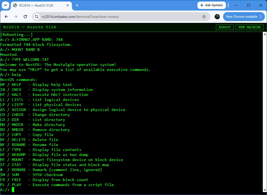
NostOS in the browser
Naturally, the machine I’m most excited to show off is NostOS. If you’ve read my earlier post, you know it has its own command-line executive, runtime-loadable extensions, reassignable logical devices, and — because speech synthesizers arekind of my thing — text-to-speech built right in. All of that runs in the emulator, with the exception that the speech doesn’t make any sound (yet). Boot it up, run `HELP`, get a directory listing, load an extension, and try out BASIC, Forth, or a game of Zork.
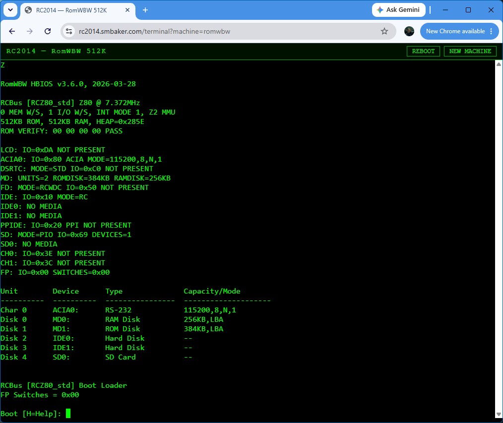
RomWBW and CP/M
For folks who want the more traditional RC2014 experience, RomWBW boots into CP/M 2.2 with a RAM disk you can actually use. Format it, SAVE a file, runDIR — it all works. Getting RomWBW to boot took a fair bit of work on the emulator side, because RomWBW probes its serial hardware carefully and drives its console with interrupts, so I had to get the ACIA, the SIO, and the Z80’s maskable interrupt handling all behaving faithfully. It was worth it — there’s something satisfying about watching stock RomWBW come up on a machine that only exists as software.
A couple things to know
The emulated machines are ephemeral. Each one lives only as long as your browser tab is connected — when you close the tab or wander off, your machine and its RAM disk are erased. So don’t write your novel in there. Think of it as a machine you sit down at, play with, and walk away from.
There are also some sensible limits in place, since this is running on a modest shared server: a handful of machines can run at once, and idle sessions get reaped after a while to make room for the next person. If you find all the machines busy, just try again a bit later.
For now I’m keeping the web-based emulator itself as a hosted service rather than releasing the source — I just wanted to get it up so people can try it. If there’s enough interest, that may change down the road.
Go try it
That’s really the whole point of this one — head over to rc2014.smbaker.com, pick a machine, and have a poke around. If you’ve been curious about the RC2014, or about NostOS in particular, this is the easiest way I know of to get a feel for it without picking up a soldering iron.
Previous post: Teleram 4000 / T-4000 Vintage Computer with Magnetic Bubble Memory