I couldn’t find myself a Hayes Chronograph, so in this video I just went off and built one…
Purpose
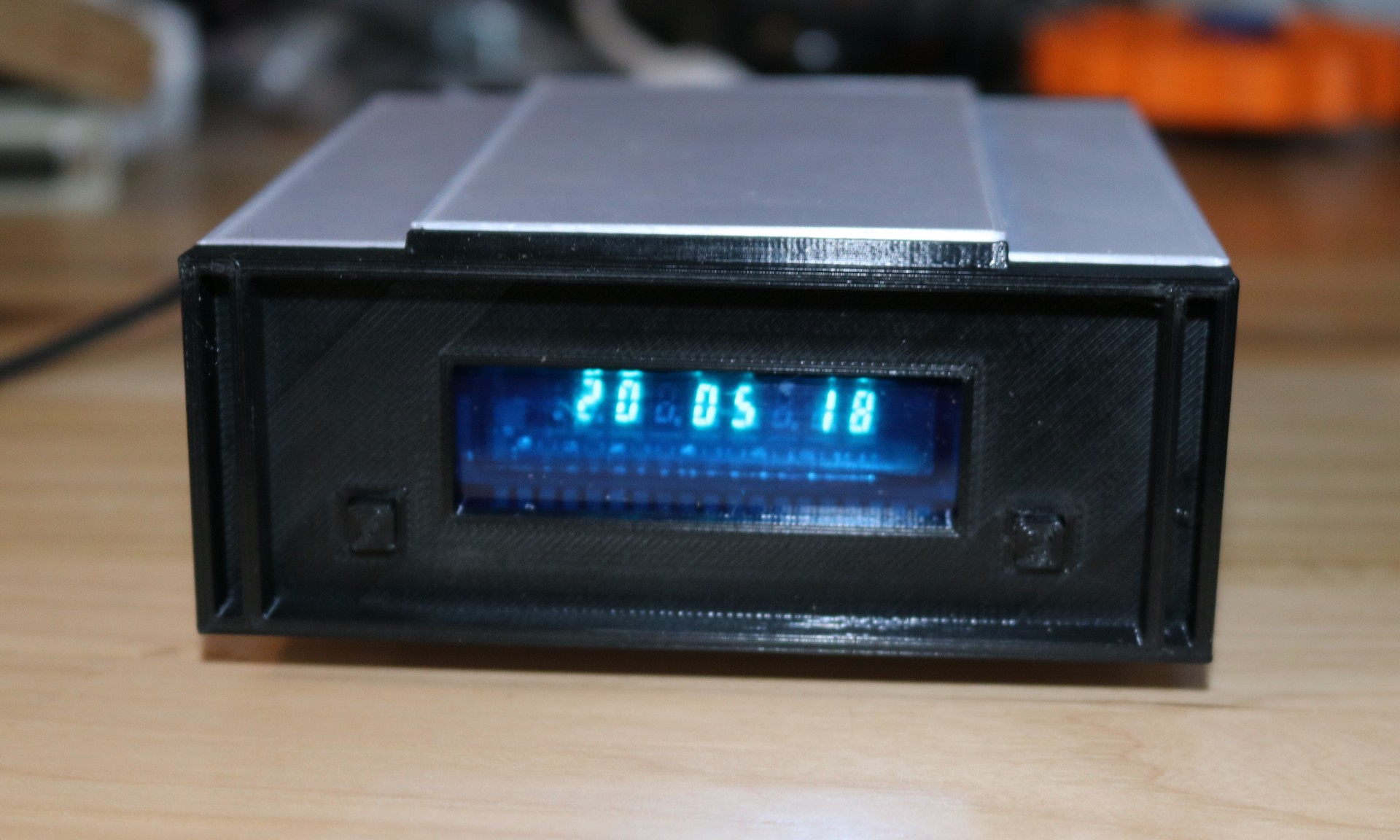
I always wanted a Hayes Chronograph, but I seem to miss the opportunity to acquire one, every time the opportunity presents itself. So I decided that in 2020 I would just have one … or else. A raspberry pi, a GPS, a 3D printed case, and an old soviet vacuum fluorescent display tube combine to finally yield me my Hayes Chronograph
Background
Hayes Microcomputer Products made modems back in the 70s, 80s, and early 90s. If you’ve heard of the Hayes “AT” command set, then you know a little bit about the Hayes modem. The modems themselves had an iconic form factor with the sleek metal case and an array of front panel LEDs.
Back in the early 80s, Hayes recognized that many computers lacked a built-in real time clock, and they decided to market an external serially-connected clock. The form factor was a slightly-taller version of the Hayes smart modem, with a nify VFD display replacing the red modem status lights. An internal pack of batteries kept the Chronograph keeping time while the power was off.
Communication to the PC was RS232 through a DB25 connector, at either 300 baud or 1200 baud. A command set similar to the “AT” modem command set was used.
These Chronographs were a niche product at the time and are fairly rare today. So I decided to make my own.
1980s Nostalgia with 2020 Features
For me, what really defines the Hayes Chronograph is the VFD display. I searched and searched and searched for a similar VFD display buy ultimately came up short. While VFD clock displays with a day-of-week indicator may have been popular back in the 1980s for devices like VCRs, they’re scarce today. A few google hits showed people reusing what appear to be VCR displays, but these look like one-off lucky acquisitions. I wanted something that was a little more available.
I settled on the Soviet IV-28B display, and ordered a pack of them from the Ukraine… and ordered them again, and again… Two attempts to order the displays disappeared during the Great Pandemic of 2020, but the third attempt finally showed up in my mailbox. The IV-28B is an 8-digit display, with a few leading symbols that are somewhat like a plus and minus. There’s a decimal point between each digit. 8 digits allows me to easily do a HH:MM:SS clock, with blanks between for separation.
To drive this display, I googled around a bit and eventually settled on the MAX6921. This chip is kind of like a shift register and high-voltage driver combined. You shift in 20 bits of data, toggle the load line, and your 20 bits will be reflected on the output drivers, each of which are capable of driving up to 76V. You shift in each digit, with a short blanking process to reduce ghosting, aand when you’ve displayed all 8 digits, you repeat the process again and again. The human eye won’t really be able to see the multiplexing. Getting the pi to handle this level of multiplexing was a bit of a challenge; I eventually ended up using the pigpio library to create a “waveform” of the multiplex, and let it replace the waveform.
That brings us to the brains of the clock, a raspberry pi. Again, we’re going for 1980s look and feel but with 2020 convenience, and a raspberry pi is pretty damn convenient. It’s able to keep up with the data rate necessary to multiplex the display, while still allow such modern conveniences as the ability to login via SSH and program it.
Finally, the clock needs a … clock. I had two options — 1) going with a battery-backed clock IC like the dallas 1302, or 2) using a GPS for automatic time setting. I decided to design both of these options into the board, but populate only the GPS option. Having the clock be able to set itself, and having the superior accuracy that comes from GPS synchronization is pretty nice.
Finally, I went with a DB25 for serial IO, just like the real Hayes Chronograph.
Schematic
Below is a picture of the schematic:
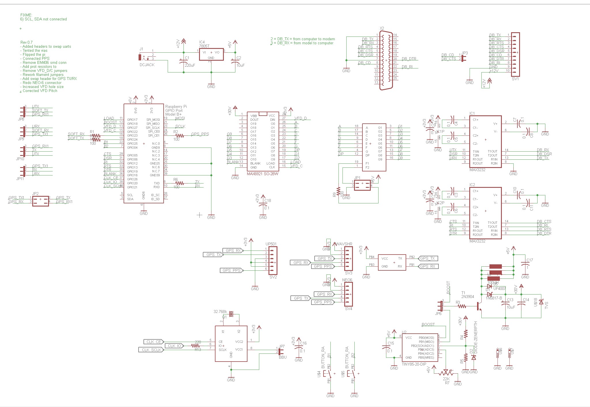
It’s pretty much as I outlined in the previous section, though let’s spend a few minutes talking about the DC/DC boost converter.
My usual go-to for high voltage supplies, the TL494 requires 12V, and I wanted a solution that was workable at 5V, so I needed an alternate controller. I think my inspiration for the boost converter came from this Hackaday article: https://hackaday.com/2014/12/07/an-attiny-boost-converter/ . The basic idea is to use an ATTINY85 to send a PWM signal to drive the boost converter (which uses an inductor, diode, and storage capacitor like a typical boost converter). The ATTINY85 continuously samples the voltage being produced and adjusts the PWM as appropriate to maintain the target voltage. The algorithm used is crude, just a simple increment/decrement; a PID controller would be more appropriate.
Implementation
Here are a couple pictures of my first prototype:
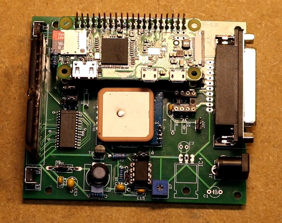
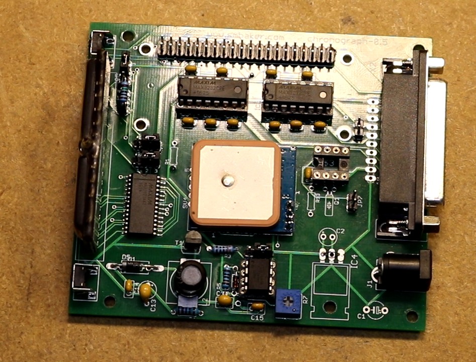
I fabricated a 3D printed case using a combination of Sunlu Silk Silver PLA (for the silver-colored parts) and Overture Black PETG (for the black parts). I generally tried to match the look and feel of the real Hayes Chronograph.
Repository
You can find the code in my github repo at https://github.com/sbelectronics/chronograph