In this post, I modify my 5th generation NUC to support 10Gbe fiber networking:
Purpose
A popular trend in homelabs is power efficiency. While some people are still buying every power-hungry used R710 they can find on eBay, others are going the opposite route, trying to maximize performance per watt. In my opinion, there’s no reason to have any more server than you need. A relatively small server is actually capable of running many VMs if the average load of those VMs is light. See my recent post titled “RAIN: Redundant Arrays of Inexpensive NUCs” for my general philosophy approaching the problem. Given the types of loads many people are running, it’s often likely that you might end up hitting a bottleneck on memory or network before you hit a bottleneck on CPU. Right now I host my home VMs on two machines: a 4th generation NUC that hosts the “mostly idle” infrastructure VMs (Grafana, VPN, pytivo, etc) and a NUC5i7RYH that hosts the VM that I use to compile and build projects. I still use my desktop Windows PC as my primary work interface, but my Linux-based “work” happens on a Linux VM. While I could run that VM in VMWare Workstation on the Windows PC, I kinda like the decoupling you get from leaving it on an always-on NUC.
As I start to upgrade my network infrastructure from 1Gbe to 10Gbe, the NUC was fast becoming one of the components left behind. NUCs are not very expandable, it’s one of the price you pay for the small form factor and the efficient operation. So, I was excited when I came across a reddit post by reddited jackharvest, where he converted a 6th Generation Skull Canyon NUC to 10Gbe. I don’t have one of these fancy Skull Canyon NUCs, I have the plain ordinary looking 5th generation NUC, so I decided to go about upgrading it.
Finally, why 10Gbe? Well the goal with a NUC-based homelab is probably to back your NUCs with iSCSI from a NAS., maybe throw in some NFS as well for home directories and projects. You end up with a lot of traffic between the NUC and the NAS, so you want to optimize that connection.
NUC Networking options
I looked long and hard to try to find a NIC that could just plug into the NUC. There are some options such as the 5Gbe copper USB-C adapter made by QNAP, but it’s going to only get you to 5Gbe, and even at that, it’s going to be limited to by the USB interface to closer to 4 gigabit. There’s a SFP+ Thunderbolt adapter, but it’s two hundred freakin’ dollars, and the 5th generation NUC doesn’t support thunderbolt anyway. There are 1gbe USB NICs that you could team/bond together, but bonding comes in second place to a real honest 10Gbe NIC.
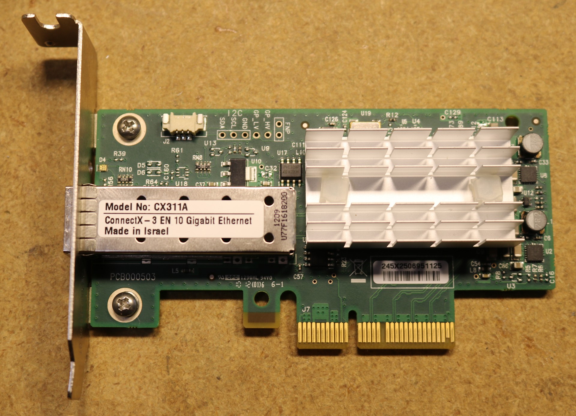
So that leaves us with finding a 10Gbe NIC. Unfortunately, there’s nothing that will plug into an m.2 slot, so we have to start with a PCI-Express adapter and work from there. The Mellanox ConnectX-3 is very popular on the used market, and can typically be had for about $29:
So that’s great, but it has a PCI-Express X4 connector and the NUC has an m.2 connector. What are we going to do about that? Well fortunately there’s this:
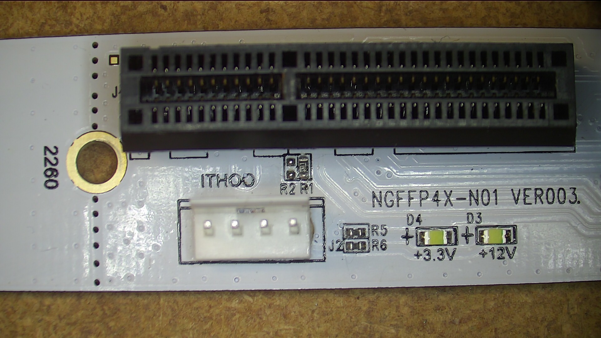
This is called an “XPLOMOS M.2 Key M NGFF to PCI-E 4X Adapter Card” and you can find it on amazon here for about $10. What it does is plug into your M-Key m.2 slot and give you a PCI-E 4X connector. The “M-Key” is important — all m.2 slots are not created equal, and different slots have different capabilities. The 5th generation NUC fortunately has the M-key slot, so we’re good there. I’m told newer generation NUCs also have the M-Key slot. Older NUCs do not.
So if we plug that adapter into the NUC’s m.2 slot, and we plug that NIC into the adapter, then our NUC ought to boot up and see a 10Gbe NIC, right?
It didn’t work
Well bummer, it didn’t work. I actually thought I had a bad card and ordered a replacement. Tried two cards, none of them worked. The NUC did not recognize the card in the BIOS. ESXi did not see it. Ubuntu did not see it. lspci didn’t show any PCI-E card.
So what now?
Well I spent some time looking at how m.2 is configured. First, there’s four config bits, named unsurprisingly config_0, config_1, config_2, and config_4. These tell what type of device is plugged into the m.2 slot. I actually manually traced these on the connector and proved they were configured right. But then I noticed, there are two unpopulated resistors marked R1 and R2. What are those for? Why is a signal running from the m.2 connector and terminating at those two pads and just doing nothing? That seems weird.
Looking into this, I think the signal is CLKREQ#, and it’s intended to be pulled low in order to enable the pci-e clock. Don’t pull it low, no clock. It might be this is a pulled-high input designed to be driven low by cards, and any card could assert the signal and enable the clock. It’s hard to get a good understanding as a lot of the documentation does not seem to be plentiful on the web, nor are there a plethora of example schematics. I figure maybe why it works for jackharvest in his 6th and 8th generation NUCs is because some other device pulls the line low, or it’s enabled by some other means, but in my case there’s nothing driving the pin and therefore no clock. I take a short in the dark and solder a 1K resistor across that unpopulated R1 pad… and … it worked! The card was detected in BIOS. The card was detected in ESXi, I’m currently rocking along at 10Gbe on my NUC.
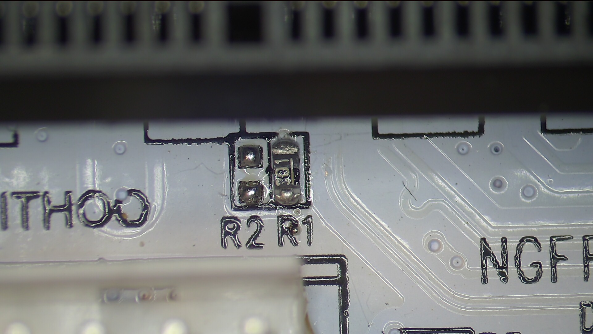
Again, if you have a 6th generation or newer NUC, this may not be a problem. We’re still collecting data on different NUC models. If you have a 5th generation, and your m.2 <-> pcie adapter isn’t working for you, then you may need to modify it. Here’s a closeup of the modified adapter. It’s the resistor marked “R1” right between the black connector and the white header.
(note that the image above shows a 300 ohm resistor; I tried 300 first, then when that worked I backed off to 1K, with 1K being a nice round number and good all-around value for a pull-down)
The resistor in question was a 1K 0603. 0603 is the “size” of the smd resistor. It’s small. You’ll need a tweezers and a hot air gun to solder the little guy in there.
So now we have it working. What next?
Let’s make it fit in the case
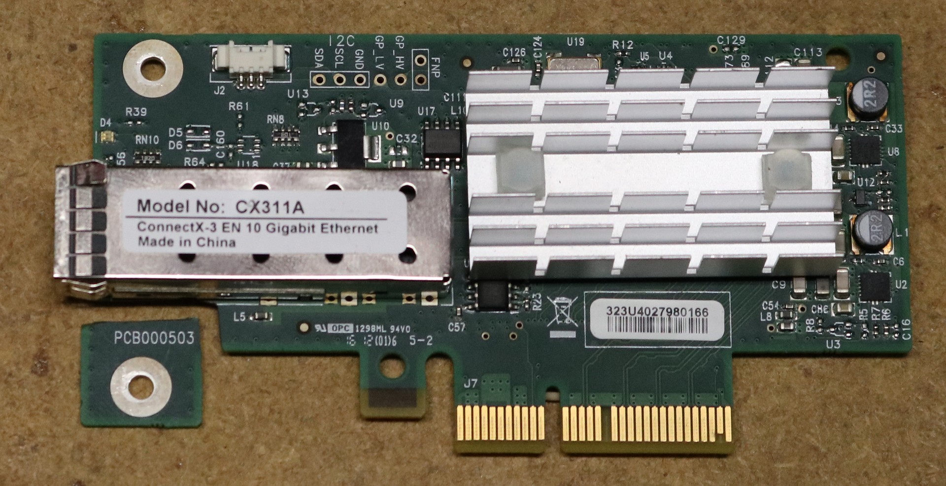
So you can’t just plug the above NIC into the adapter, because it’s going to hit the side of your NUC case. I sorta skipped over that point above. You’re either going to have to modify the NIC, or hack a slot into the side of your NUC case:
Be really careful cutting the Mellanox NIC PCBoard like I did in the first shot. In fact, be so careful that you just don’t do it at all. This is a multiplayer PCB, at least 5 layers, probably 6. There appear to be no signal traces where I cut it, but there are at least three planes, which could be power or ground. Shorting those planes could damage something. I really though I had damaged the NIC when I chopped it, and gave up and slotted the NUC case and used an unchopped NIC instead. Only later did I realize the NIC wasn’t actually damaged (turned out to be that CLKREQ# problem talked about above). Anyhow, if you’re going to proceed this way, then I recommend mutilating the NUC case rather than mutilating the NIC. Alternatively, you can opt for what reddit user jackharvest did, and use a ribbon-cable slot externder to move the NIC so it doesn’t interfere with the case. He was able to achieve a much tighter case design than I did, didn’t need to chop slots in anything, but he had to add a ribbon cable. Either way, there’s lots of ways to do this mechanically.
Buck converter
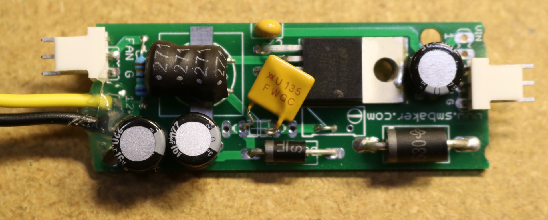
The mellanox card reqiress 12VDC, and the m.2 <-> pcie adapter has a header for 12V, but we have no ready source for 12V power inside of the NUC. The NUC itself runs off 19V. So I made a small buck converter using a LM2576 regulator:
You don’t have to build your own buck converter — you can buy them ready made on ebay very cheaply, usually adjustable with a 25-turn pot. The one I built above used an LM2576-12, so it’s fixed at 12V (no potentiometer needed) and has a plug for a fan connector as well as an 80 ohm dropping resistor for the fan to slow it down a bit.
3D Printed Case
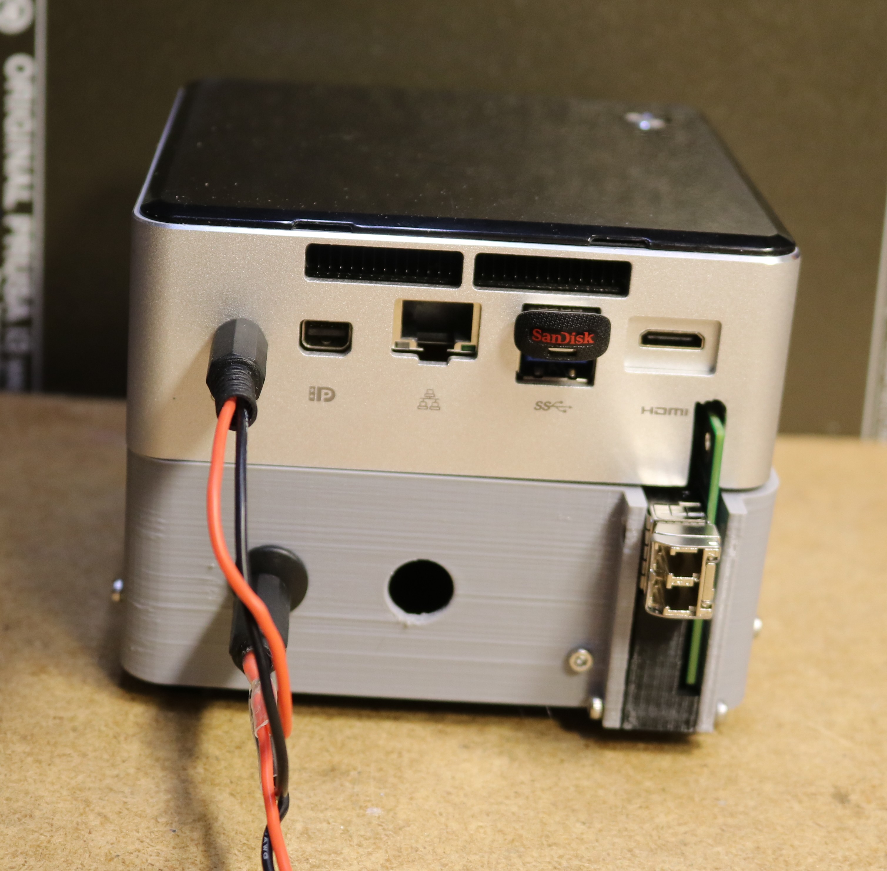
Here’s a picture of my final 3D printed case. It’s not quite perfect, particularly because I could only use three machine screws to mount the extension to the NUC rather than four (the fourth was too close to the NIC). It got the job done though, and I’ll probably come up with something to cover the remainder of the exposed PCB.
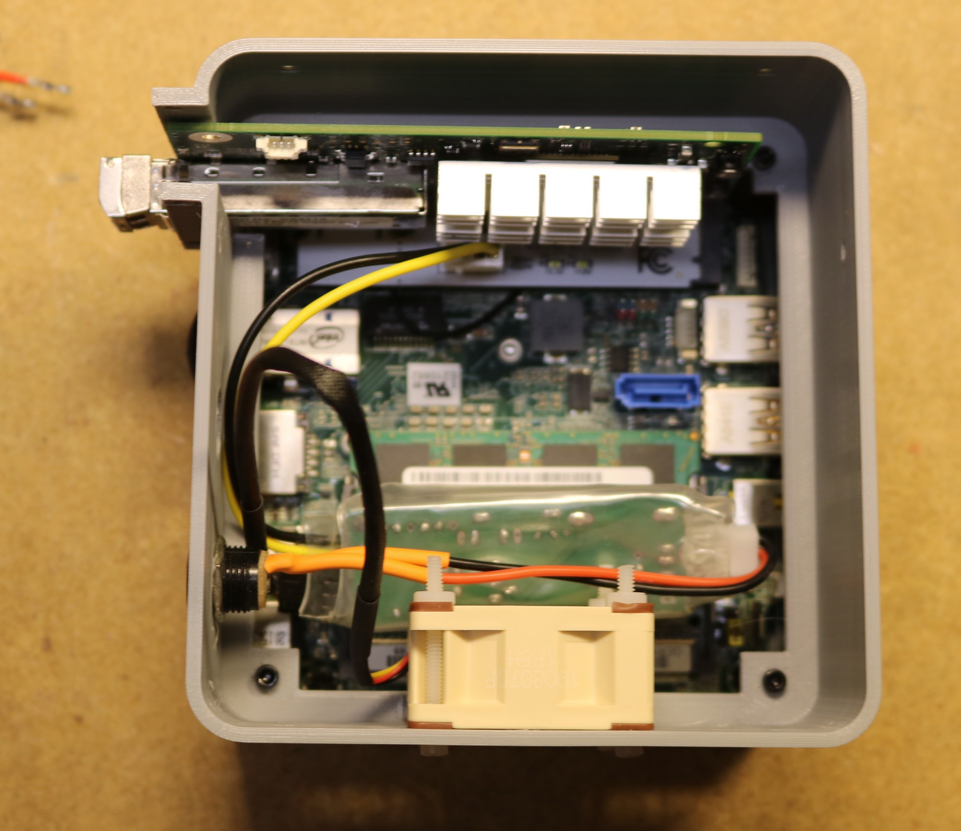
Here’s a view up from the bottom of the case:
You can see a 40mm noctua fan at the bottom. Immediately above that is the buck converter stuff into place, it’s encased in three layers of clear shrinkwrap tubing.
Performance
The performance is great. I performed the following tests between iperf3 running on my Windows 10 desktop and iperf3 running in a VM in ESXi on the modified NUC. With a Brocade ICX6450-24P switch in between.
iperf3 – 1 thread: 5.51 Gb/s
iperf3 – 2 threads: 8.08 Gb/s
iperf3 – 3 theads: 8.23 Gb/2
Three threads at 8.23 Gb/s I think is about where it tops out. My understanding is that we’re hitting the limitations of the PCI-E bus here, which is 250gb/s, but that 8-bit transfers are encoded as 10 bits. So you top out around 8 gigabit. That’s what I read at least, and it seems consistent with my measurements.

Hi, I realize that it’s been a few years since you did this mod, but I am stuck with a similar situation…without the success that you had. I did try those same pcie boards like you, but I was unaware of the resistor mod…and I don’t have any resistors anyway, but I wish I knew if the solder short would work. Anyway, I returned those adapters and bought one of the extension boards (ADT-Link, the kind with the board with a long cable to a physical x4 slot) this has a similar pad but labeled runclk#, however this on actually has a very thin current path between the two pads…Well this one doesn’t show up in the bios either. Is there something special that I need to configure in the bios? I’ve tried various settings in addition to Optimized Defaults, but so far nothing lights up Devices > PCI. I’m just trying, like you, to add 10GB networking to a few Gen5 NUC5i7RYH. Thanks for any info you can provide. Cheers, Patrick