In this video, I build a memory/IO expansion for the vintage Heathkit ET-3400 trainer:
Purpose
I’ve always wanted one of these Heathkit microprocessor trainers, and finally one caught my eye on eBay and I pulled the trigger. The basic interaction with the trainer is through the onboard keypad and LED displays, but Heathkit also made an accessory that added additional ROM, RAM, serial port, and a cassette interface.
This allowed you to use a machine monitor over the serial port, and even featured a Tiny Basic interpreter in ROM that allowed the trainer to be programmed in Basic.
Design
The schematics for the ETA-3400 are well published on the web, and you can readily see exactly how Heathkit implemented the original accessory. One option would have been to faithfully reproduce the original, but that would have been a little inconvenient in comparison to some of the more modern ICs that are available now. Rather than using eight static RAMS and a pair of ROMs, we could simply use one larger RAM and one larger ROM. Rather than implementing address translation in a ROM, it could be done in programmable logic. A modern MAX202 could easily replace the handful of transistors and discrete components used in the original. While slightly newer, these choices are still in the vintage theme of the original.
Below is the schematic:
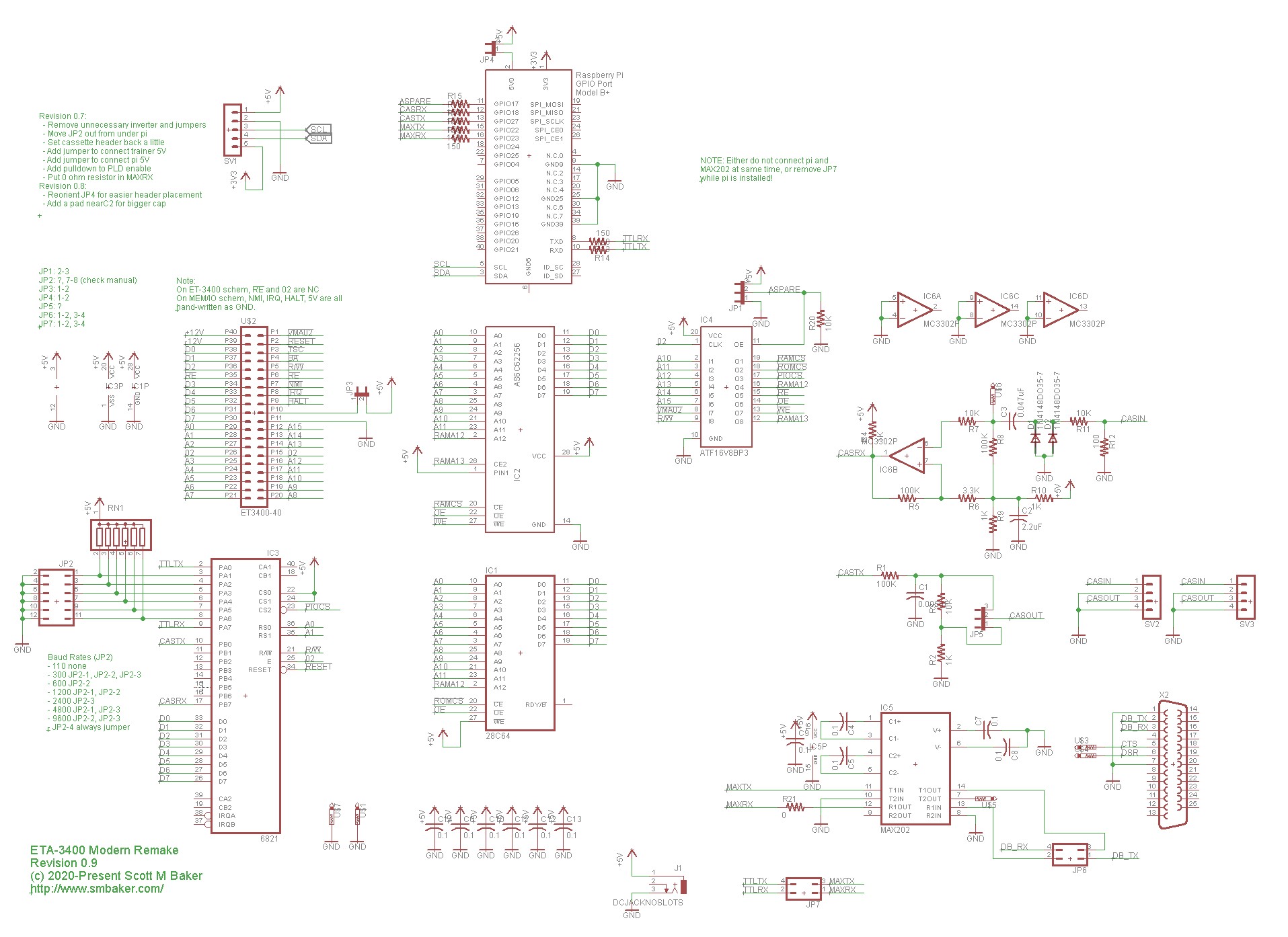
IMPORTANT NOTE: Although I designed the circuit to take either an AS6C62256 SRAM or an AS6C6264 SRAM, I had some trouble with part substitution. I recommend you stick with the recommended part, a 70ns 62256. When I tried a 55ns IC (either 62256 or 6264), behavior was erratic.
There’s a lot going on, so click the schematic to get a larger view, or download the PDF in my github repo.
The large 2×20 header is the ribbon cable from the ET-3400. It contains the data bus (D0-D7), the address bus (A0-A15), clock (02), power and ground, and several control lines. Noteworthy control lines include:
- vma.02, asserted when the CPU wants to access memory,
- R/W, asserts when the CPU wants to write (vma.02 and r/w together indicate a write; vma.o2 without r/w indicates a read)
RAM and ROM use a 62256 and 28C64 respectively. The RAM footprint I used was technically for a AS6C6246, and that *should* work, but in my prototype all I had as AS6C62256. If you’re ordering parts, I recommend the AS6C62256 just to be consistent and it’s a negligible cost difference for a more capable RAM.
The PIA, MC6821, is right out of the heathkit schematic. It’s a general-purpose peripheral interface and is used to interface to the serial port and cassette. The serial interface makes use of a MAX202 RS232 level converter, which is then plumbed out to a DB25 connector. The hex inverter interposed between the PIA and MAX202 is not needed, just leave it out and set the jumpers to bypass it.
The cassette circuitry is straight out of the heathkit schematics. It outputs audio via an RC network and voltage divider. It inputs the audio using a comparator. I have not tested the cassette interface yet, but I attempted to faithfully reproduce the heathkit circuit.
Address decoding makes use of a ATF16V8 programmable logic device. This take the upper address bits (A10..A15) and asserts the appropriate chip enable (RAMCS, ROMCS, or PIACS).
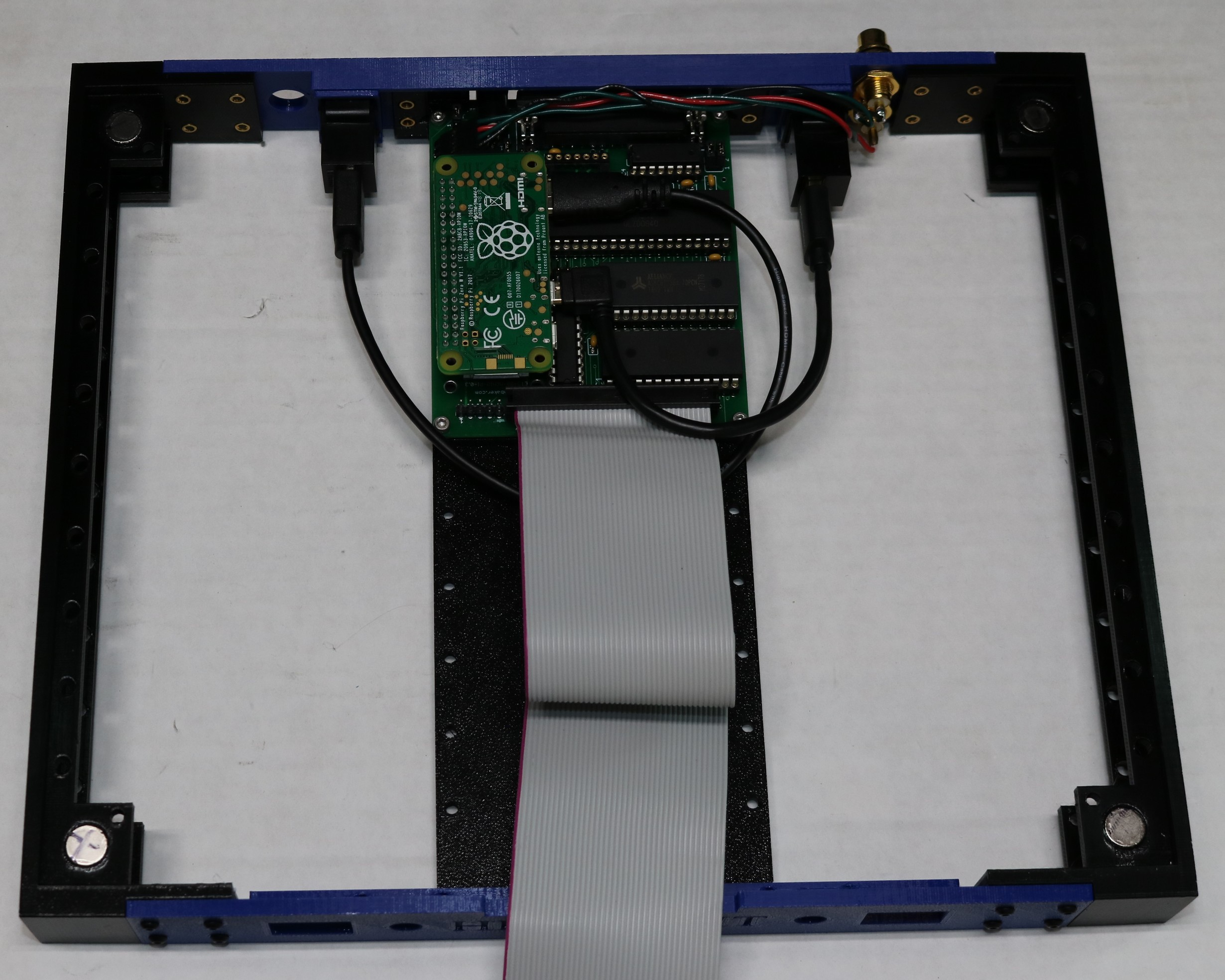
An optional feature is a raspberry pi header. A pi zero w can be added to the board and will be connected to the serial and cassette interfaces. This allows you to hide a pi inside the case and have remote SSH access to your trainer (or hook up the HDMI and USB to drive a display and keyboard). As I said, the pi is entirely optional.
Jumpers
| JP1 | PLD Spare. For future use. |
| JP2 | Baud Rate. See schematic. The first three positions select baud rate. The fourth position should always be jumpered. The fifth and six positions are not used by the ROM, but could be used by a user program. |
| JP3 | Trainer Power. Shorting this jumper enables the board to get power from the ET-3400’s expansion connector. Leave the jumper unpopulated if you’d rather use external power (via the barrel jack) instead |
| JP4 | Pi Power. This connects 5V to the raspberry pi header. If you’re not using a raspberry pi, then don’t be concerned with it. If you are using a pi, then it makes a handy header for a power switch to turn the pi on/off (or just leave it connected all the time) |
| JP5 | Cassette Gain. The 50mv is if you’re using the microphone input on your cassette recorder, and the 500mv position is if you’re using the AUX jack. |
| JP6 | Max202 to DB-25. This allows you to implement a null-modem if you want. Jumper them straight across (1-2,3-4) for normal operation, or flip the jumpers (1-3, 2-4) for null modem. |
| JP7 | PIA to Max202. This jumper block connects the serial TX and RX from the PI to the MAX202 driver chip. For normal operation it should be present (jumper 1-2, 3-4). If you’re installed the raspberry pi, then you’ll want to remove this jumper. |
Implementation
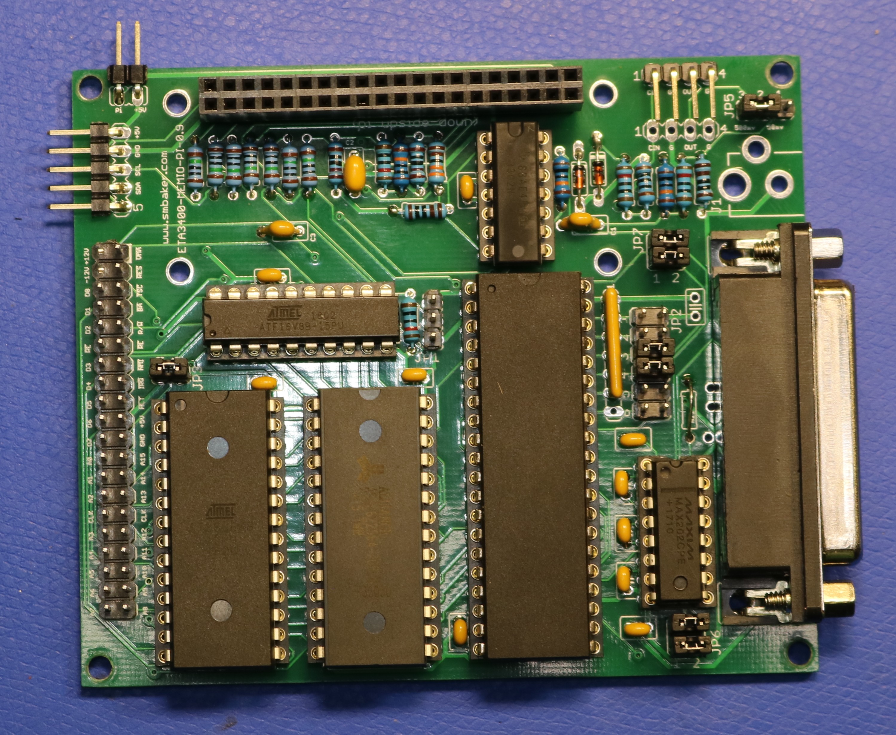
A picture of the PCB is below:
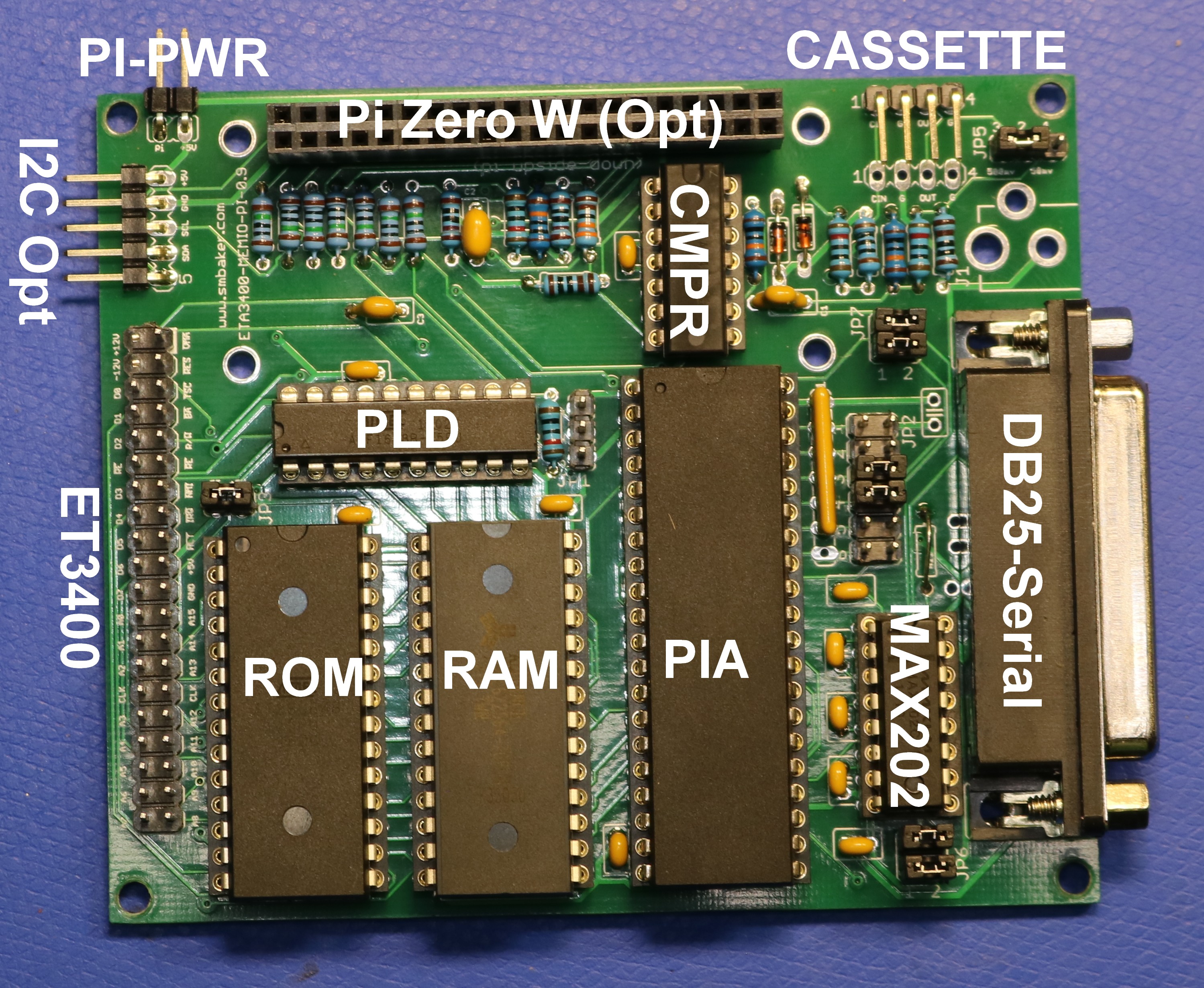
Here’s an annotated picture:
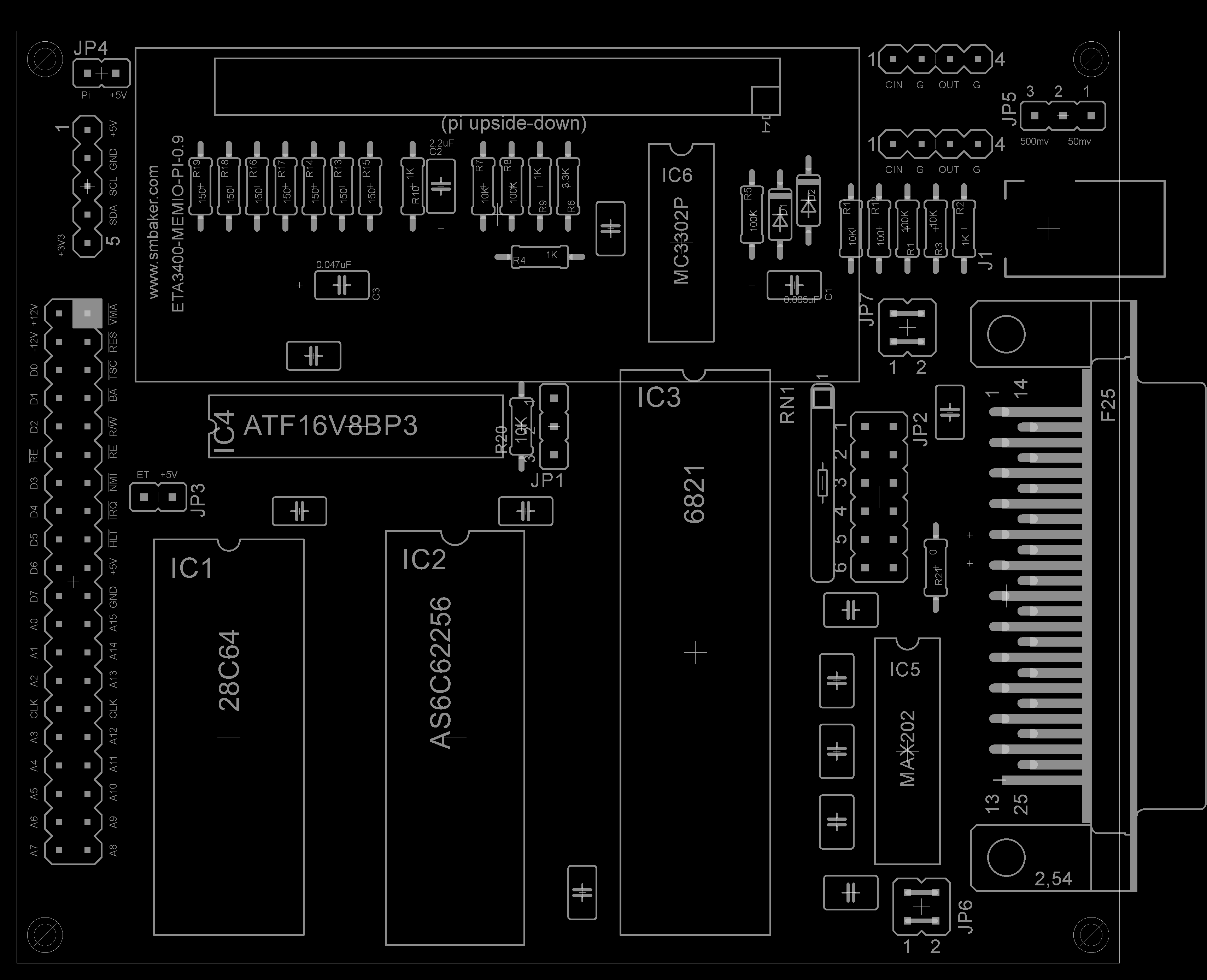
Here is a component placement diagram (click the image to get a high resolution view; there’s also a PDF in the github repo that may be easier to read):
BOM
Here is the part list:
| Part | Value | Quantity | Description | Source | |
|---|---|---|---|---|---|
| C1 | 0.0047uF | 1.0 | digikey BC2683CT-ND | ||
| C2 | 2.2uF | 1.0 | digikey 445-173575-1-ND | ||
| C3 | 0.047uF | 1.0 | digikey BC2686CT-ND | ||
| C4-C14 | 0.1uF | 11.0 | bypass capacitor | digikey 399-4264-ND | |
| 470uf/16V | 1.0 | additional stability when using pi; place across the 5V and GND pins of SV1 | |||
| D1, D2 | 1N4148 | 2.0 | digikey 1N4148FS-ND | ||
| IC1 | 28C64 | 1.0 | EEPROM | digikey AT28C64B-15PU-ND | |
| IC2 | AS6C62256 | 1.0 | RAM | digikey 1450-1182-5-ND (use the 70ns version, not the 55ns) | |
| IC3 | 6821 PIA | 1.0 | PIA | ebay | |
| IC4 | ATF16V8BP3 | 1.0 | PLD address decode | digikey ATF16V8B-15PU-ND | |
| IC5 | MAX202 | 1.0 | serial driver | digikey MAX202ECPE+-ND | |
| IC6 | MC3302P | 1.0 | comparator | digikey 296-17223-5-ND | |
| J1 | DCJACK 5.5×2.1 | 1.0 | [Optional] external power | digikey CP-002A-ND (not verified, looks right) | |
| JP1 | 1×3 header | [Optional] spare input to PLD | digikey, S1012EC-40-ND (cut to size) | ||
| JP2 | 2×6 header | Baud select jumper | |||
| JP3 | 1×2 header | Jumper, enables power from ET3400 | |||
| JP4 | 1×2 header | Jumper, enables power to pi socket | |||
| JP5 | 1×3 header | Jumper, cassette output gain | |||
| JP6 | 2×2 header | Jumpers, ser output | digikey, S2012EC-20-ND (cut to size) | ||
| JP7 | 2×2 header | Jumpers, max202 | |||
| R1, R5, R8 | 100K | 3.0 | digikey S100KCACT-ND | ||
| R2, R4, R9, R10 | 1K | 4.0 | digikey S1KCACT-ND | ||
| R3, R7, R11, R20 | 10K | 4.0 | digikey S10KCACT-ND | ||
| R6 | 3.3K | 1.0 | digikey S3.3KCACT-ND | ||
| R12 | 100 ohm | 1.0 | digikey S130CACT-ND | ||
| R13-R19 | 150 ohm | 7.0 | RasPi protection resistors | digikey S150CACT-ND | |
| R21 | 0 (jumper) | 1.0 | a chunk of wire will do | ||
| RN1 | 2.2K x 6 SIP | 1.0 | 2.2Kx6 bussed sip resistor | digikey 4607X-101-222LF-ND | |
| SV1 | 1×5 RA header | 1.0 | [Optional] I2C header from pi | digikey S1111EC-40-ND (cut to size) | |
| SV2 or SV3 | 1×4 RA header | 1.0 | digikey S1132EC-40-ND (cut to size, tall) | ||
| U$2 | 2×40 header | 1.0 | digikey, S2012EC-20-ND (cut to size) | ||
| X1 | RASPI_BOAR | [Optional] Header for Pi Zero W | |||
| X2 | DB25 | 1.0 | DB25 connector | Digikey, AE10935-ND | |
| shunt jumpers | Digikey, S9337-ND | ||||
| CAB1 | 40-ribbon | 40 pin ribbon cable | ETA-3400 to ET-3400 cable | ||
| IDC1, IDC2 | 2×20 IDC conn | 2×20 IDC ribbon cable connector | ETA-3400 to ET-3400 connectors |
Instead of CAB1 and IDC1/IDC2, you can probably hack up an old 40-pin IDE cable. If you do opt to do so then you may need to shorten the IDE cable if it’s excessively long (carefully pry off one connector, move it where you want and then carefully crimp it back down)
Notes
- I opted to plumb through several PIA lines to the raspberry pi for future use. These all go through 150 ohm resistors for protection, but in some cases there can still be interference if the pi is erroneously outputting a signal. Most notable, this happens on GPIO18, which is connected to the Cassette RX. If you’re pi is setup to output sound on GPIO18, then it may interfere with loading programs from tape. Usually “gpio -g mode 18 in” will remedy this. Alternatively, you can leave R16 off. In fact, you can probably leave R15-R19 off.
- The raspberry pi presents quite a bit of load on the ET-3400’s power supply. When using an onboard pi, I suggest placing a 470uF capacitor across the 5V and GND pins on the expansion board. The SV1 header is an excellent place to do this.
- Keep the ribbon cable between the expansion board and the ET-3400 as short as practical. The longer the cable, the more the potential for interference.
- The ET-3400-A modification instructions for adding the expansion header call for adding EMI/RFI shield of some sort to the trainer. This is probably not a bad idea, particularly with the ribbon cable wrapping around under the trainer as it does.
3D printed case
I made a 3D printed case. It’s about an inch tall and sticks to the bottom of the ET-3400 with magnets:
Resources.
- My github repo at https://github.com/sbelectronics/eta-3400 is where you’ll find any source code, PLD images, and even gerbers.
- The ET-3400 group at https://groups.io/g/ET-3400 was helpful to me developing this project and has many resources including the original Heathkit schematics.
Saw this on Hackaday and I love this! I have an ET-3400 and have kept an eye out for ETA-3400s on eBay, etc. but I can’t imagine paying $300-$400 for one. I’m seriously tempted to reproduce your design. Thanks for the effort!
I’ll probably be putting some bare pcboards up on ebay soon. Made a few revisions to the board currently depicted in the article to move a couple components around (get a header out from under the raspberry pi, etc). Once that board design has been vetted, I’ll be updating the github repo with the new gerbers.
I’ll keep my eye out for the updated gerbers. If you do a board run for eBay, how do you plan to let people know?
Hello
I’m considering giving your clone a try. One question I have is in regards to the ROM. What do we do with burning the rom. I don’t see any details in your article or am I missing something?
Da I just downloaded your Github
All info is there, thanks for all your hard work!!!
Parts procurement seems to be large problem as of Dec. 2021. No 70ns RAM, EEPROM not available, PLD not available. Digikey wants to program them for buyer. Ideas?
I just completed building a unit and it works great with my ET-3400! I plan to make a YouTube video about it.
I found the PLD at Mouser. I had suitable RAM and EEPROM on hand.
For those interested, when 3d printed, the “side” parts are a friction fit for the Shuttle Hot-419 486 baby-AT motherboard. The front and back are also the correct measurements to make a complete mount that encompasses the entire perimeter of the motherboard. It’s almost like the design was originally for a baby-AT motherboard from the beginning.