In this post, I design sound and speech boards for the Epson QX-10 computer.
Purpose
I’ve been having fun with my Epson QX-10 — in the previous blog post I built a compactflash IDE storage device for it. But, the computer has four more expansion slots and I want to fill them out. I figured I’d start simple. The AY-3-8910 is a popular sound chip for Z80 based systems; I was last introduced at it when looking at Ed Brindley’s sound board for the RC2014. I knew it would be relatively simple to interface. The SP0256A-AL2 speech synthesis IC is also quite easy to work with, having designed boards to fit it to an RC-2014 and a PC myself. I’d have preferred to do a Votrax SC-01A board, but the votrax ICs are much less plentiful than the SP0256.
Sound Board
Below is the schematic for the sound board:
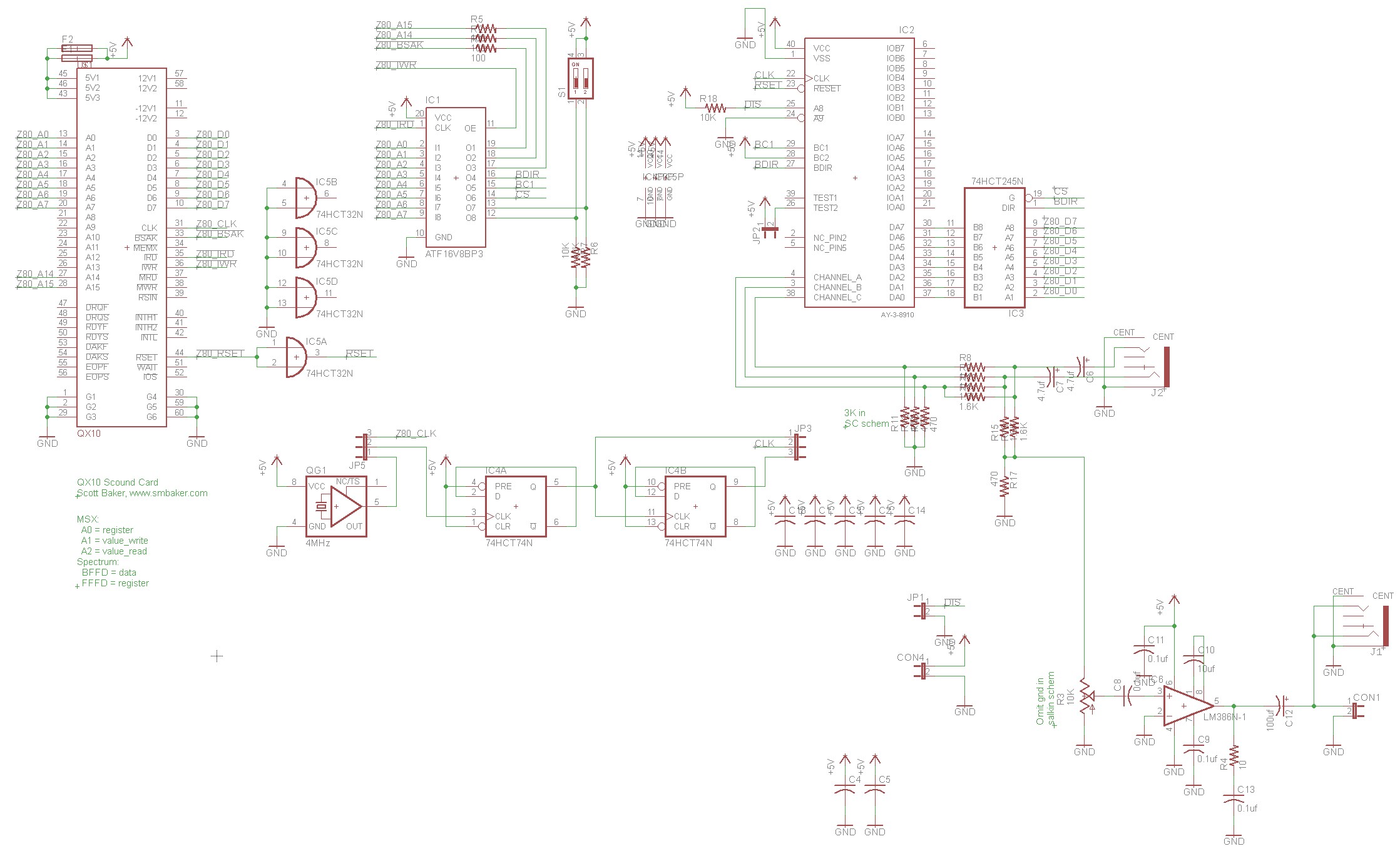
The sound chip is the venerable AY-3-8910. This thing is a little bit wonky in how the control signals work:
| BDIR | BC2 | BC1 | AY-3-8910 Function |
|---|---|---|---|
| 0 | 1 | 0 | Inactive |
| 0 | 1 | 1 | Read from Sound chip |
| 0 | 1 | 0 | Write to Sound chip |
| 1 | 1 | 1 | Latch register address |
I explored the typical mappings on the MSX and the ZX spectrum. The MSX-style addressing (ports A0 – A2) seemed most appropriate, but the QX-10 already has an option board that can be placed there. So I ended up putting my board at 0xD8. This lines up nicely with the default address on my IDE board, which is 0xD0.
| Computer | Set Register | Write Data | Read Data |
|---|---|---|---|
| QX-10 Sound card (www.smbaker.com) | 0xD8 | 0xD9 | 0xDA |
| MSX | 0xA0 | 0xA1 | 0xA2 |
| ZX Spectrum | 0xFFFD | 0xBFFD | 0xBFFD |
To perform this addressing, I used an ATF16V8B programmable logic device (PLD). PLDs are relatively period-accurate, and they allow you to implement several logic gates in a single IC. An advantage of the PLD is that it can be easily reprogrammed if a mistake is made. The PLD handles translating the address lines (A0-A7) the BSAK, read and write strobes, etc., and generates the BDIR, BC1, and CS signals. Find the pld files in the pld/sound directory in my github repo.
The CS signal together with the BDIR signal are used to select a bidirectional data buffer, because buffering the IO on the card is good practice.
Audio output is mixed together via a resistor mixing network and fed into an optional LM386 amplifier. You can use the LM386 to drive a speaker, or use the audio-out jack with an external speaker.
JP3 and JP5 are used to select the clock. I use JP3=1-2 and JP5=2-3 to select the QX-10’s internal clock, and to divide that clock by 2 to get a 2MHz clock to the AY-3-8910. You could choose to instead use an external oscillator by jumpering JP5=1-2.
Below is a picture of the completed sound board, with the default jumpers:
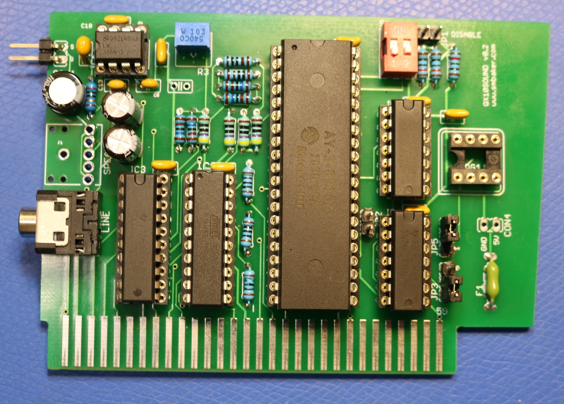
The board is a straightforward implementation of the schematic. As pictured above the optional crystal oscillator is not installed, and it is jumpered to use the QX-10’s clock, divided by 2. The dip switches should be set to off-off, or left uninstalled.
For playing sounds, I modified Wayne Warthen’s tune player that is included on the RomWBW distribution.
Speech Board
Below is the schematic for the speech board:
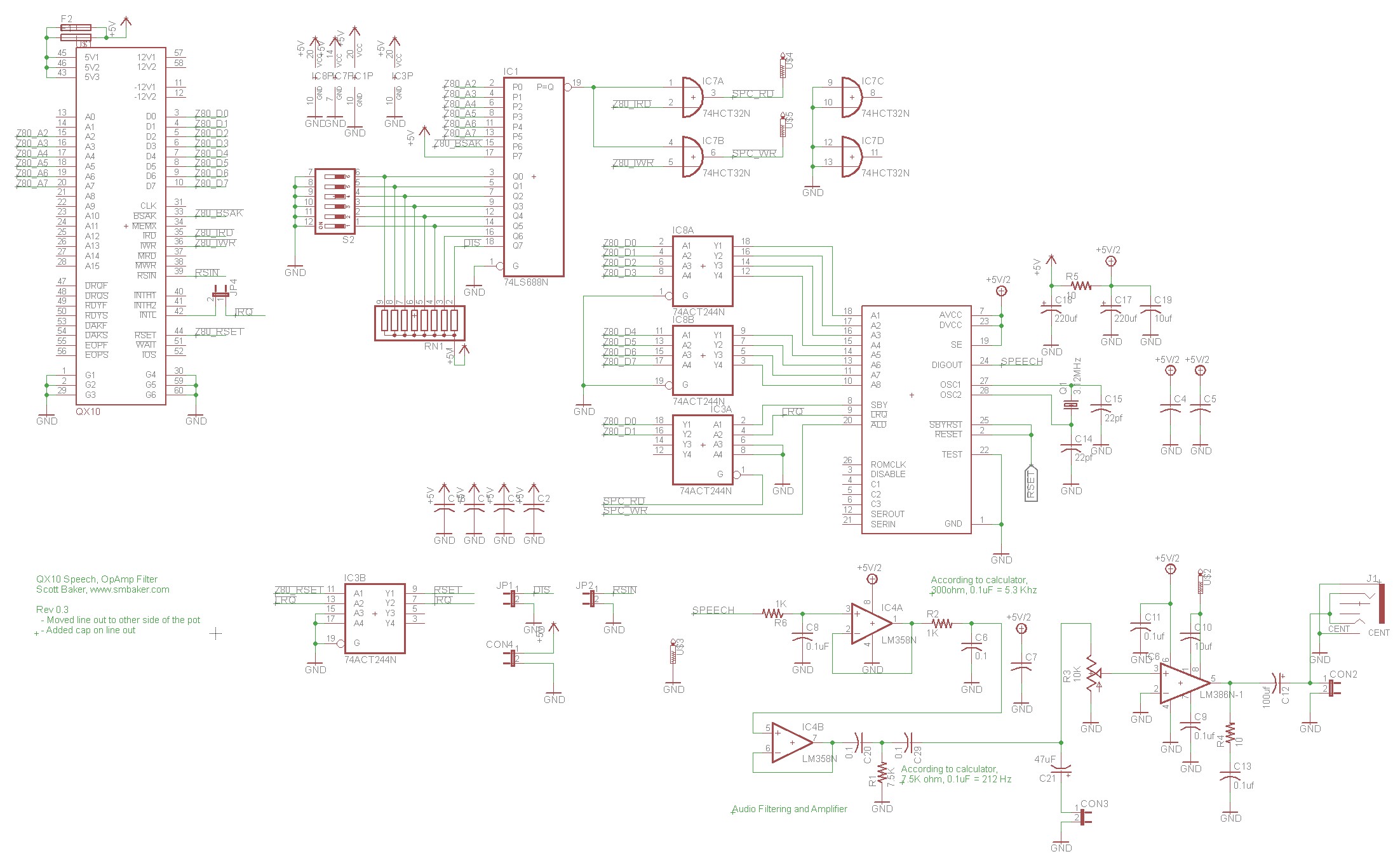
I went a little bit different route on the speech board than on the sound board. Rather than used a PLD, I used a good ol’ 74HCT688 magnitude comparator and a dip switch. Set the dip switches to off-off-on-off-off-off to place the speech board at its default address of 0xDC (right along side its friend, the sound board). A 74HCT32 is used to combine the CS out of the 74HCT688 with the IO Read (IOR) and IO Write (IOW) strobes from the QX-10. For writing, we trigger the ALD pin on the SP0256 to load a phoneme off the data bus. When reading, we use a 74HCT244 to put the STB and LRQ signals onto D0 and D1. This allows you to write a phoneme to 0xDC, and then loop reading 0xDC and wait for D1 to go low.
You should also be able to install a jumper on the INT pin, and have the speech synthesizer generate interrupts when it is ready for a new phoneme. I have not tried this.
As with the sound board, I used a LM386 as a mono amplifier. There are two low-pass filters straight out of the SP0256 data sheet. The data sheet calls them 5KHz filters, but my math does not add up. I’ll trust the datasheet knows what it’s talking about. I did add an LM358 op-amp to post-process the sound before we feed it to the LM386. I found that the op-amp reduced noise on the speaker.
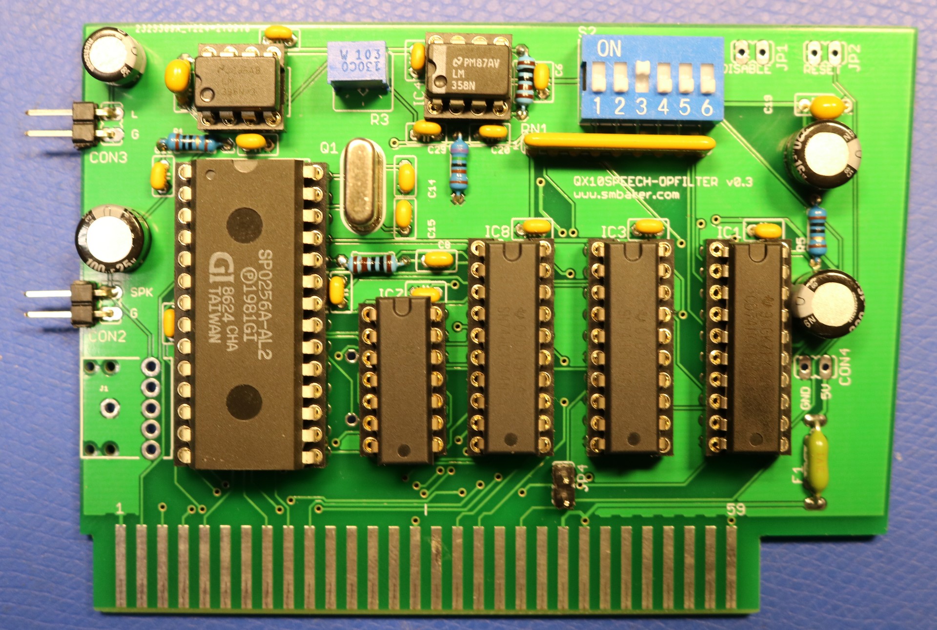
Below is a picture of the completed board:
Resources
My github repository contains code, disk images, etc.
pld/sound/sound.jed– binary version of PLD for the sound board. Burn it with a TL866 or similar EPROM programmer.images/sound.img– disk containing music player (tune.com) and several PT3 files. I couldn’t get the MYM files to play correctly, only the PT3 files. This disk is 16 sectors of 256 bytes each for the first two tracks and 10 sectors of 512 bytes each for the remaining tracks.asm/tune.asm– my hacked-up variant of Wayne Warthen’s tune.com music player.images/speech.img– contains TALKER.BAS, a program for testing the speech synthesizer. As with the sound board, this image is 16 sectors of 256 bytes each for the first two tracks and 10 sectors of 512 bytes each for the remaining tracks.