In this blog post, I build a raspberry pi based DDS VFO for my Drake Ham Radio
Purpose
My Drake R-4C/T-4XC Amateur (Ham) Radio has been a lot of fun, but it can also be a lot of work keeping it on frequency. The mechanical nature of the VFO/PTO assembly I think lends itself to frequent drift as temperatures shift, or as the voltage inside the receiver changes. In addition to being hard to keep on frequency, it’s also hard to dial into a desired frequency, as very tiny movements of the dial are necessary. Especially when you’re using digital modes, like FT8 (and yes, I do FT8 on the old tube Drake), you want the frequency to remain constant.
One solution is to use a digitally synthesized frequency to drive the radios rather than their internal variable oscillators. Modern ICs can put out a pretty stable digital frequency. No more drift, and easy to dial in to exactly what you want.
Drake Basics
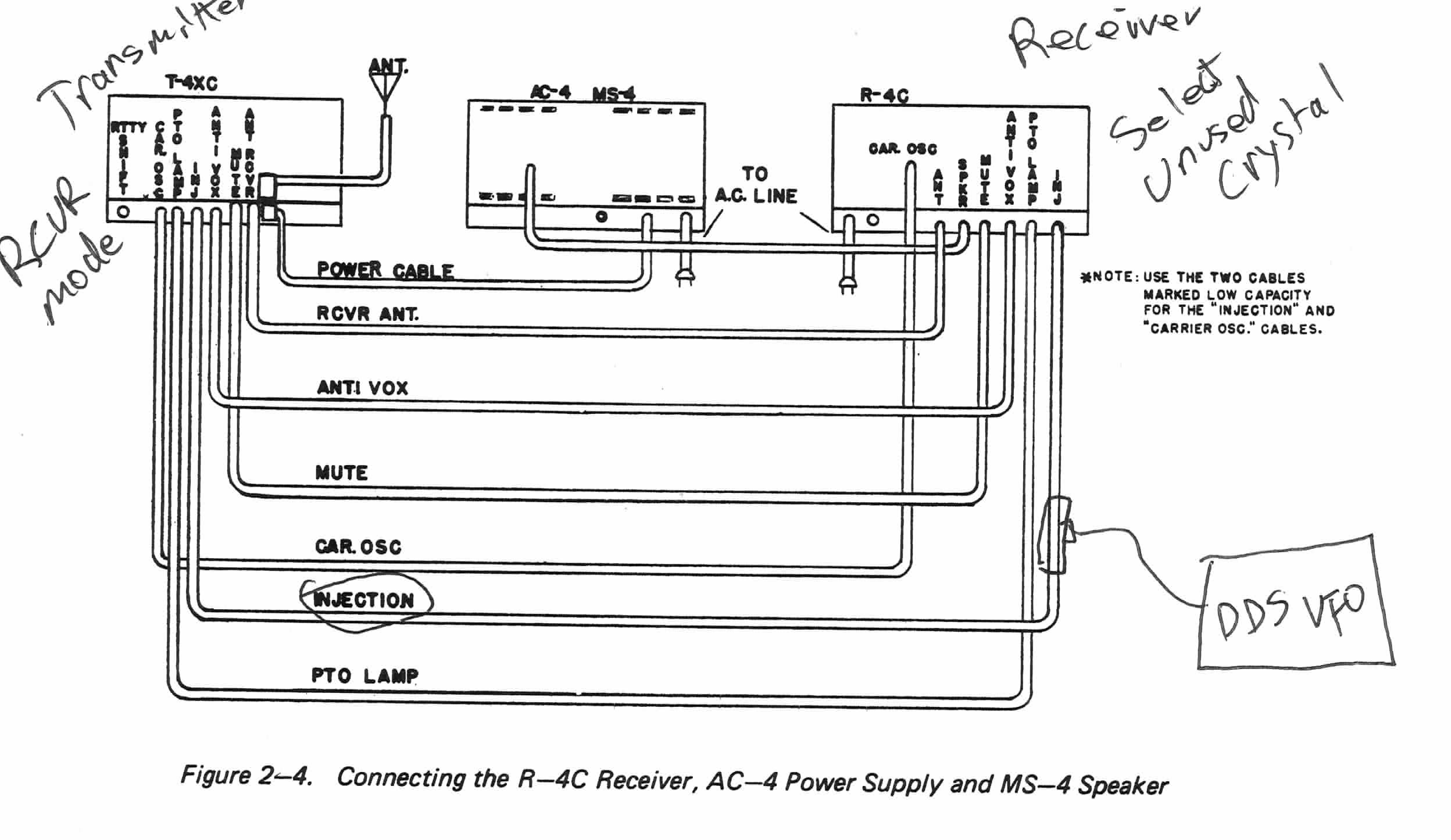
There is an injection line that connects the Drake twin receiver and transmitter. This injection line can be used in either of two ways, Receiver -> Transmitter (RVCR Mode), or Transmitter -> Receiver (XMTR Mode). It can also be ignored entirely (SEPARATE Mode). This line carries your desired frequency plus 5645 KHz. For example, if you want to tune 7.074 MHz, then the INJ line will be at 12,719,000 Hz. If you want to tune 29.5 MHz, then it’s at 35,145,000 Hz.
Tuning the transmitter is easy; the transmitter will happily accept an AC waveform at its INJ connector so long as the transmitter is in RCVR mode.
Tuning the receiver is a little more tricky. It outputs on the INJ line, unless it see a DC signal in the neighborhood of about -27V (it’s still an oscillating waveform, it just has a big negative DC offset applied to it). This is what happens when you put your transmitter in XMTR mode. However, there’s an additional way to pull this off — if you switch the receiver to an unused crystal socket, the local oscillator will not oscillate, and it’ll happily pick up whatever AC waveform you supply on the INJ port, even without the big negative DC offset.
So the first approach would be to stick a Tee on the INJ line, switch the receiver to an unused crystal, and then put our digitally synthesized waveform onto that INJ line. This works, sort of.
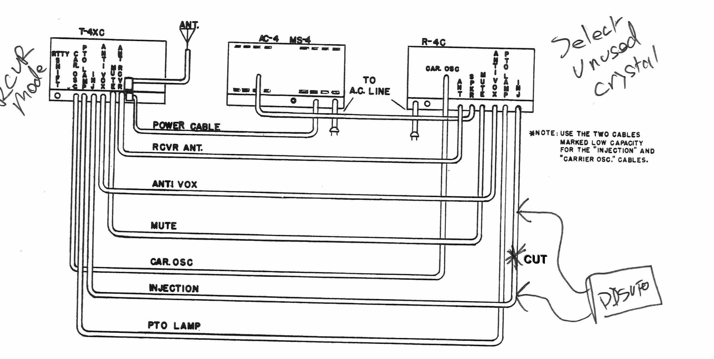
The problem with this approach is that the receiver tends to attenuate the injection signal, especially if you are either poorly aligned, or if you don’t have the preselector set right — there are coupling capacitors tuned to the preselector knob position. Remember, the Twins were not really designed for a signal to be injected to both of them this way. The attenuated signal then does a poor job of driving the transmitter, and I saw low output power.
For that reason, in this article, I will show a DDS-VFO with two drivers, so we can cut the injection cable, and drive the Transmitter and Receiver separately:
DDS ICs
There’s lots of choices these days for the DDS IC. I went with an AD9850, which is the same IC that K3JLS uses in his DDS-VFO for the TR7. This IC is cheap and there are carrier boards readily available on ebay and on ali express:

Twelve bucks may be cheaper than you can buy just the components yourself, and it’s certainly cheaper than you could assemble the thing yourself. Sometimes these premade modules can be a deal.
Schematic
The schematic is shown below:
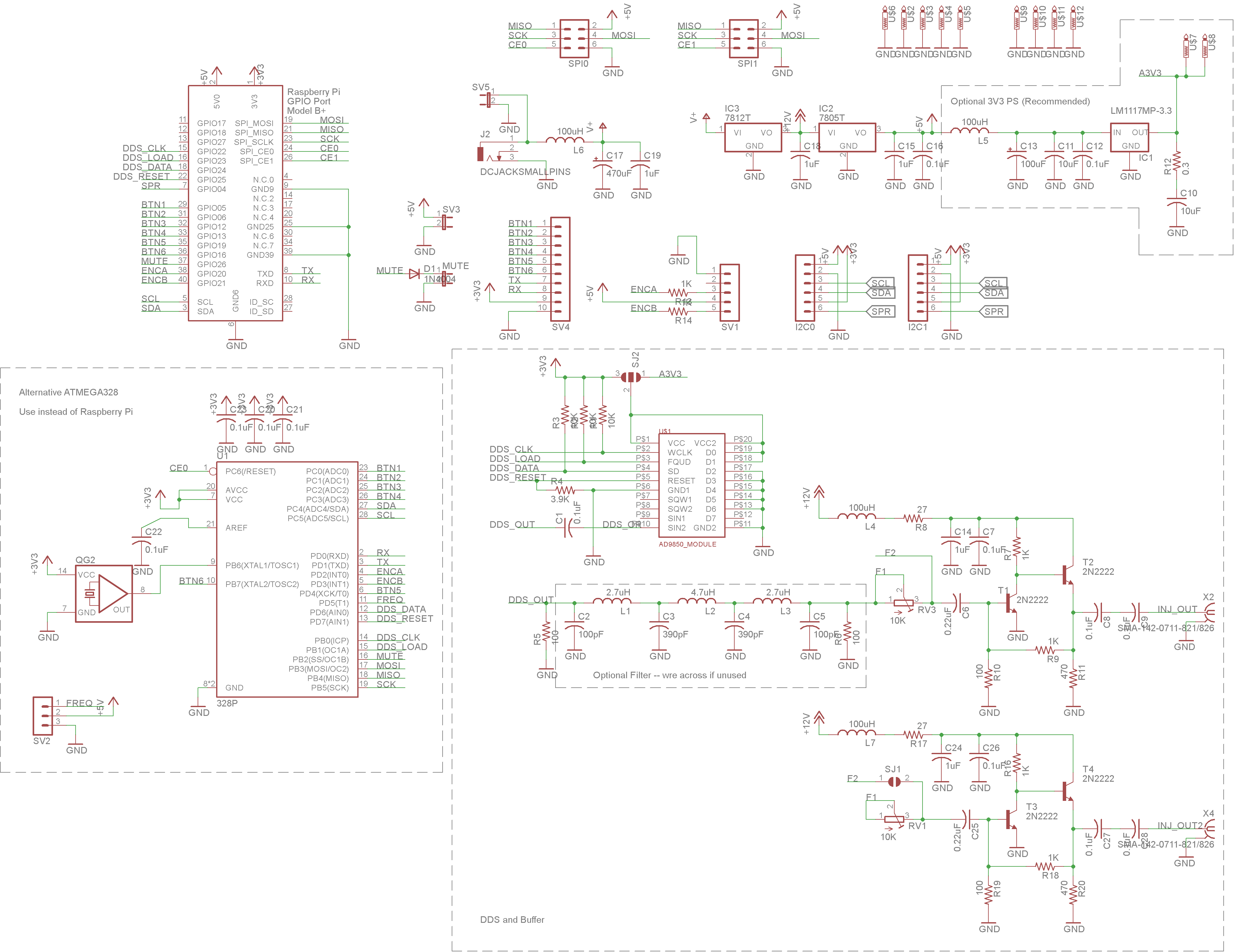
The upper left is a raspberry pi, connected in the traditional way. The lower left is an atmega328, just in case you’re the type of person that a raspberry pi is not for you. The lower right section is where it gets interesting.
The DDSVFO is driven by four lines — clk, load, data, and reset. It works like a shift register. You clock in your data and then hit the load line to load the data and make it active. The DDS-VFO outputs a waveform that we couple with a capacitor and then send to an optional butterworth filter. The butterworth filter came from K3JLS’s design, and as shown is not appropriate for this application because it has a 7 MHz rolloff, and we actually need a ~ 35 MHz rolloff. So just wire it across for now. I’ll come back to this and experiment with appropriate component values some day in the future.
After the butterworth filter (which you’ll just wire straight across, right?), there are a pair of output drivers. Each one uses a 10K pot for level control and then a two transistor driver using 2N2222 transistors. The buffer came from K3JLS as well, but I think it’s also the same circuit used by AA8V and W8DIZ.
I power the AD9850 module with 3.3V. There’s two options for this, either the 3.3V output from the pi, or an onboard 3.3V regulator using an LM1117-3.3. Using the pi’s regulator save a few parts, but you will hear artifacts from the pi on your receiver — if the pi executes a power-intensive operation, such as executing a command when you type it at the SSH prompt, you’ll hear a tick or snap on the audio. For that reason, I recommend using the separate dedicated 3.3V supply.
The 7812 regulator is option. If you plan to power this with 12V, then just wire the 12V regulator across.
The mute input can be used to implement separate transmit and receive frequencies. When the T-4XC goes to transmit, it’ll ground the mute line. We could detect this, and switch frequencies. I don’t implement that, yet.
All that remains is a bunch of headers for SPI and I2C peripherals, and the rotary encoder. I used a bourns optical encoder with 128 steps per revolution. You want a high-quality optical encoder like that, not a cheap low-step mechanical encoder. Find something cheap on eBay. I used 1K protection resistors on this, as I powered the encoder from 5V, and the pi is a 3.3V device.
Implementation
A picture of the completed prototype is shown below
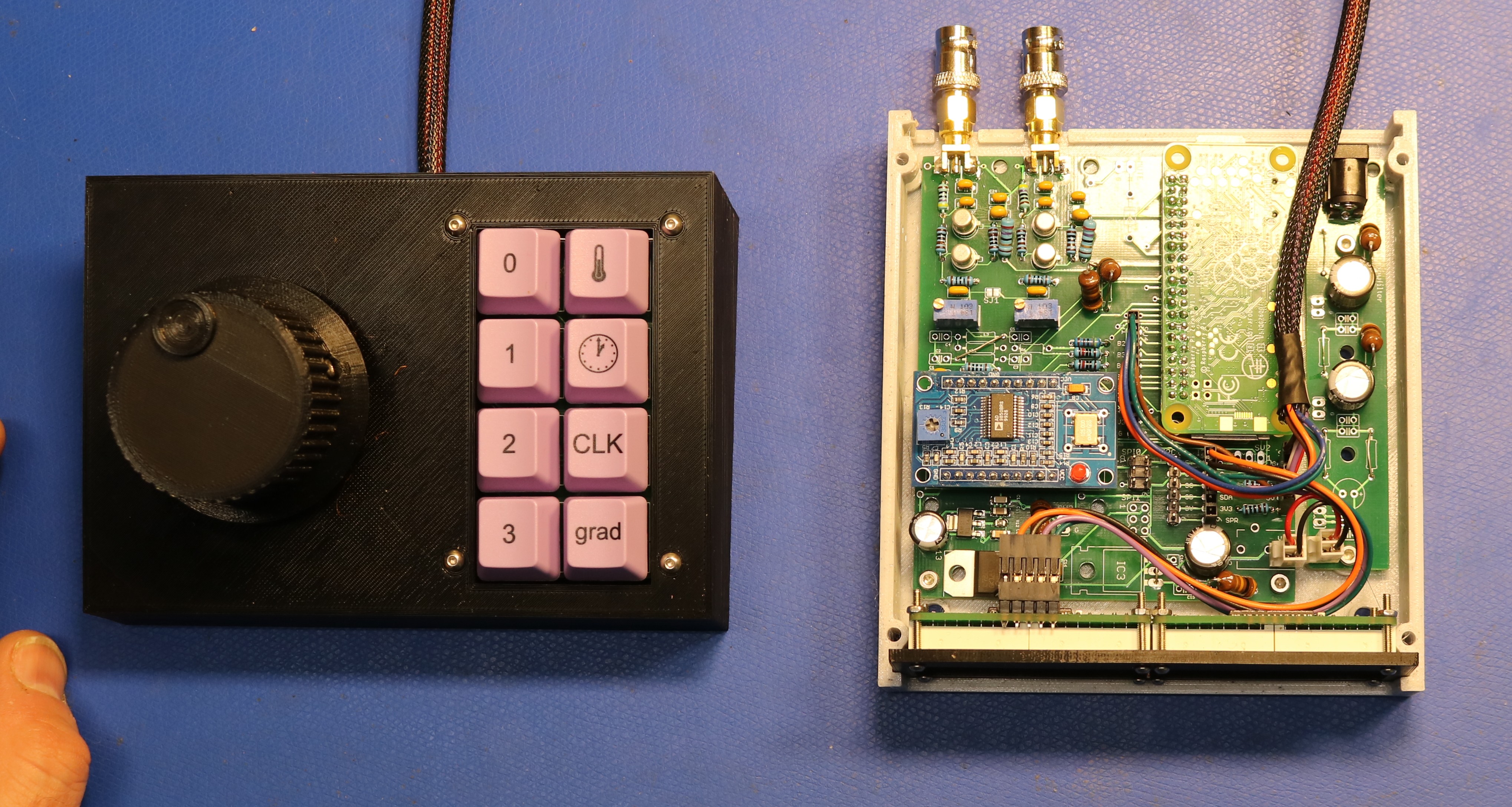
On the left is my rotary encoder and keypad. The keypad uses cherry MX blue keyswitches. Pay no attention to the legends on the keycaps, I used spares from other projects. I’ll probably have WASD Keyboard print me up some custom keycaps once I’ve decided on all the functions.
On the right is the DDS-VFO unit. You can see a pi zero w upside down on the right, and the DDS module to the left. On the back are two SMA jacks, to which I’ve attached BNC-to-SMA adapters. Directly below the SMA jacks are the transistor buffers. One output section to the TX, and one output section to the RX.
On the front are two quad alphanumeric display units. Adafruit sells these boards, though in this case I respun their board to make it easier to daisy-chain. They’re controlled via I2C.
Resources
Below are some useful resources:
- Scott’s Github Repo, with the python source code
Very Nice work indeed. I was once tempted to interface my DDS VFO with Drake gear I could replace the analog dial with one of the 6 digit units sold on eBay and shoot the output of the DDS VFO right into the existing VFO circuit before the buffer. This way, if the Drake twins were set up for transceive, the receiver would also control the transmit with no need to mess around with the injection line. But – I dismissed this ‘temptation’. Joe – K3JLS
Scott, Neat project thank you for sharing. I’m considering a project like this for my Drake TR-4CW and I would need to make a few mods as there is no INJ line input and I wouldn’t need the second amplifer. But did you happen to save gerber files or have any extra printed PCB. Any thoughts on making this available as a Kit? There might be some interested folks on the drake groups io forum including myself. Chris de WX7V
Hi Scott,
Do by any chance have ability to share the boards so we can get them printed by someone like PCBWay? Is there any other documentation such as parts list, etc.? Also, since you did this three years ago are there any new implementations you’ve seen that are more recent that you like or would recommend? Thank you.
Best,
Joseph