In this post, I prove a broken clock can be right more than twice a day:
Background
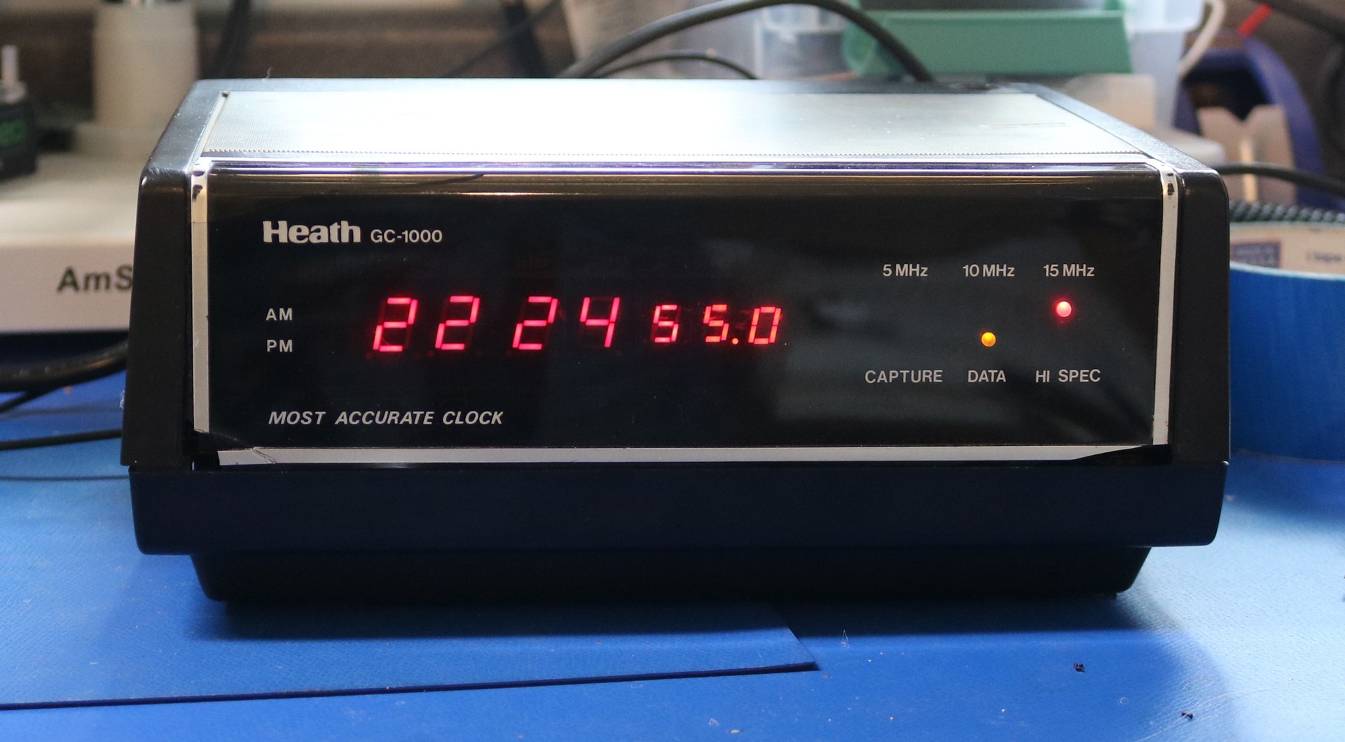
The Heathkit GC-1000 Most Accurate Clock is a timepiece from 1983 that receives time broadcasts on the WWV or WWVH stations operated by the US Government. These stations are received at 5MHz, 10MHz, or 15MHz. The clock is capable of automatically scanning all three of these frequencies, or you can lock it to a specific frequency.
These signals are broadcast from Colorado and Hawaii. How well you receive these signals depends on everything from local interference to sun spots and atmospheric behavior. 15MHz is most active during the day. 5MHz is most active during the night. 10MHz is most active during the transitions between night and day. Here in Oregon, I typically receive the Colorado broadcast, though I’ve been known to occasionally pick up the Hawaii broadcast, or even to pick up both broadcasts at the same time.
These broadcast, over the course of approximately 40 seconds encodes a series of bits that tell the current time and date. There’s also a man (for Colorado) and a woman (for Hawaii) that will recite the next time timestamp near the end of each minute interval. The time is encoded using a series of 1000Hz and 100Hz tones.
The GC-1000 continuously attempts to receive these WWV (or WWVH) signals and uses the timestamp not only to set itself to the current time, but to also trim its internal oscillator so that the accuracy of the clock between syncs improves over time.
The Clock Purchase
I found a broken clock on eBay and purchased it.
The seller’s listing described the clock as “powers on, lights up, but then nothing happens” and “missing some screws”. Never having owned one of these clocks before, I assumed it was indeed broken, but having better than average diagnostic skills, I figured I stood a good chance of being able to fix it.
First, a GC-1000 that doesn’t show any digits is not necessarily a problem. The clock does not display the time until it was synced with WWV. It can sit like this for four minutes, four hours, four days, or for-ever. To make the clock display the time, you have to give it a strong WWV signal (perhaps even from an external antenna). It has to receive an accurate time signal from WWV two (or three?) times in a row before it will sync the time. This can be a bigger hurdle than you might give it credit for.
Diagnosis
I tore the clock apart. It was not only missing some screws, but the plastic standoffs that mounted the top shell of the clock to the bottom had broken and been previously discarded. The top and bottom shells had evidence of some velcro remnants, so it seems to previous owner had been holding it together with velcro. Connectors to the RF board had been left disconnected. The potentiometers on the tone board showed evidence they had been fussed with.
The GC-1000 has an internal switch that will place it into diagnostic mode. The manual for the GC-1000 tells you exactly what to do. I flipped the switch and the display flashed erratically between lighting all digits and lighting nothing. It kept flicking on and off randomly. Sometimes it would respond to the diagnostic pushbutton and sometimes it would not. Once it displayed “1000 2” but then it flickered back off as soon as it had displayed it.
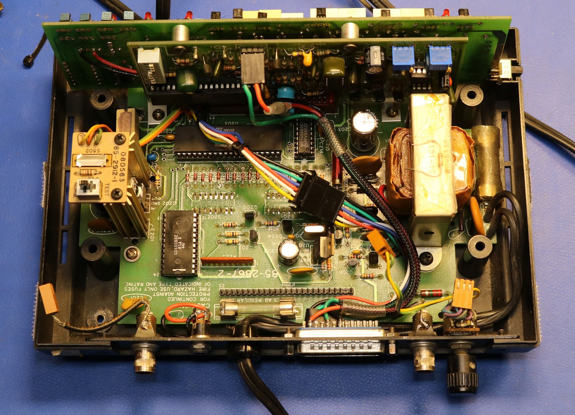
I tore down the part (watch the video and you’ll see a similar teardown). I removed all boards. The bottoms of the boards had a black goo residue, some remnant of the flux. I could see that it had either been recapped, or the original build had gone awry and damage had been repaired. The damage was around C212, a capacitor, and U202, a 5V regulator. Putting the board under the scope, I was able to determine that although a previous owner had attempted to replace C212 and repair the traces, he/she had not repaired the trace from the microcontroller to C212. This trace is the microprocessor’s reset line.
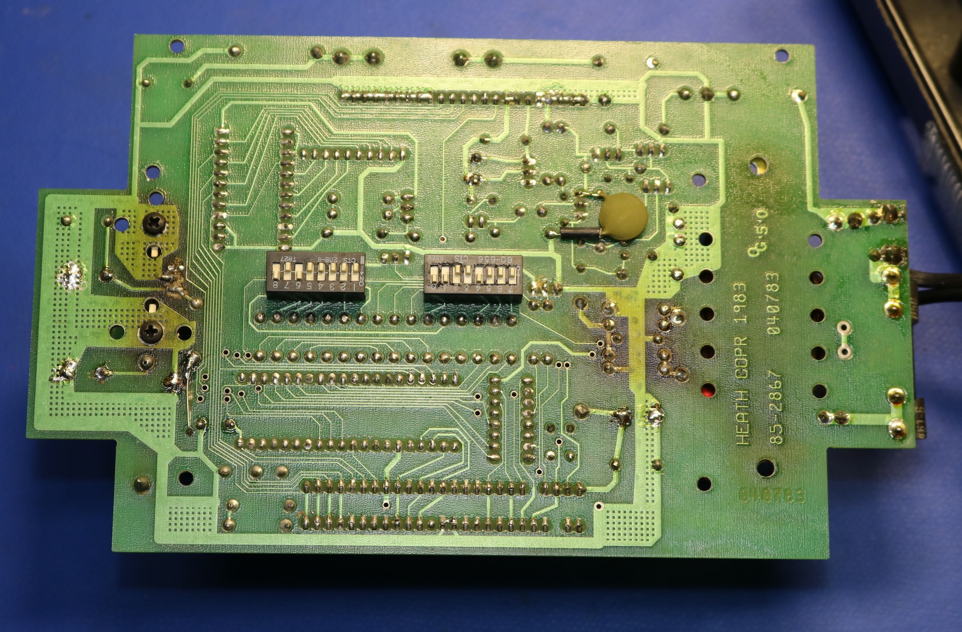
And just like that, the problem was solved and fixed. The damaged trace had left the microcontroller’s reset line floating, and because of this it was suffering from spurious resets. I scrubbed off the black goo with alcohol and a toothbrush. I replaced all the caps on the main board (while it’s out, might as well give it a thorough recapping), and I reassembled the clock.
Now the diagnostic mode worked, and I was able to adjust the tone board for 1000Hz and 100Hz tone matches according to the manual.
I spent some time fussing with it, trying to get it to sync, eventually gave up, and sat down at the computer to do some work.
First Sync
Some hours later I stretched, looked around the office, and exclaimed “<expletive>! The clock is displaying a time! <explective>!!!”.
A watched clock never syncs. The key is to not give the thing any attention, and it will surprise you.
At this point, I started shooting parts of the youtube video, to show the functioning clock. I also moved it over to its permanent display location, and I cleaned up the antenna wiring.
Last sync
Moving the clock seemed to doom my success. Over the next two weeks, it would occasionally, rarely, sync. If I unplugged it and plugged it back in, it might sync or it might go days before syncing again.
I became increasing frustrated and started spending time and money on antennas
First Antenna: Internal Random Wire
My first antenna was a random wire along the ceiling in my office. Being inside the office, it did not require me to go outside and run wires, nor did it lead to any unsightly “ham radio antennas” sticking out of the home that someone could complain about. The indoor random wire seemed to often pick up strong signals, but the clock still would not often sync.
Second Antenna: External Random Wire with a 9:1 Unun
For the second antenna, I figured I would run an inconspicuous external random wire. I also built a 9:1 unun, because that’s what the Internet said I needed.
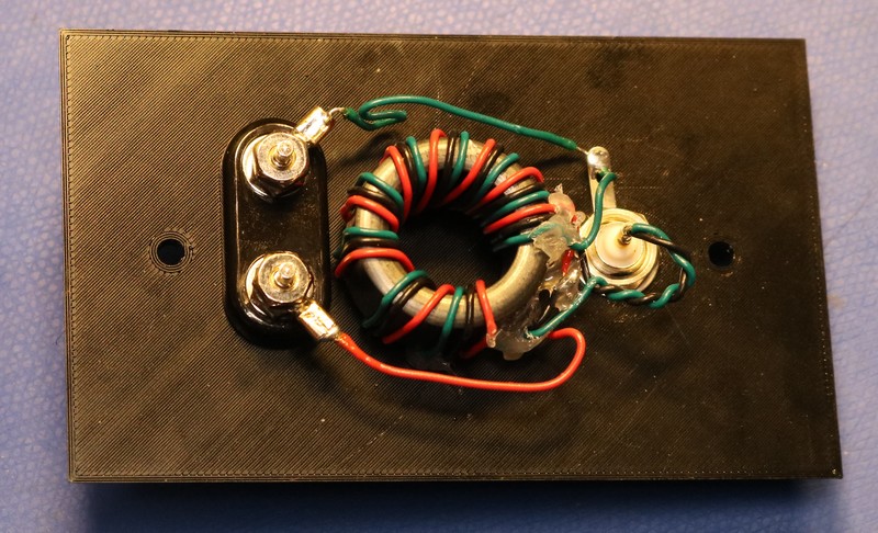
The second antenna didn’t work much better than the first. Maybe a little. Not much.
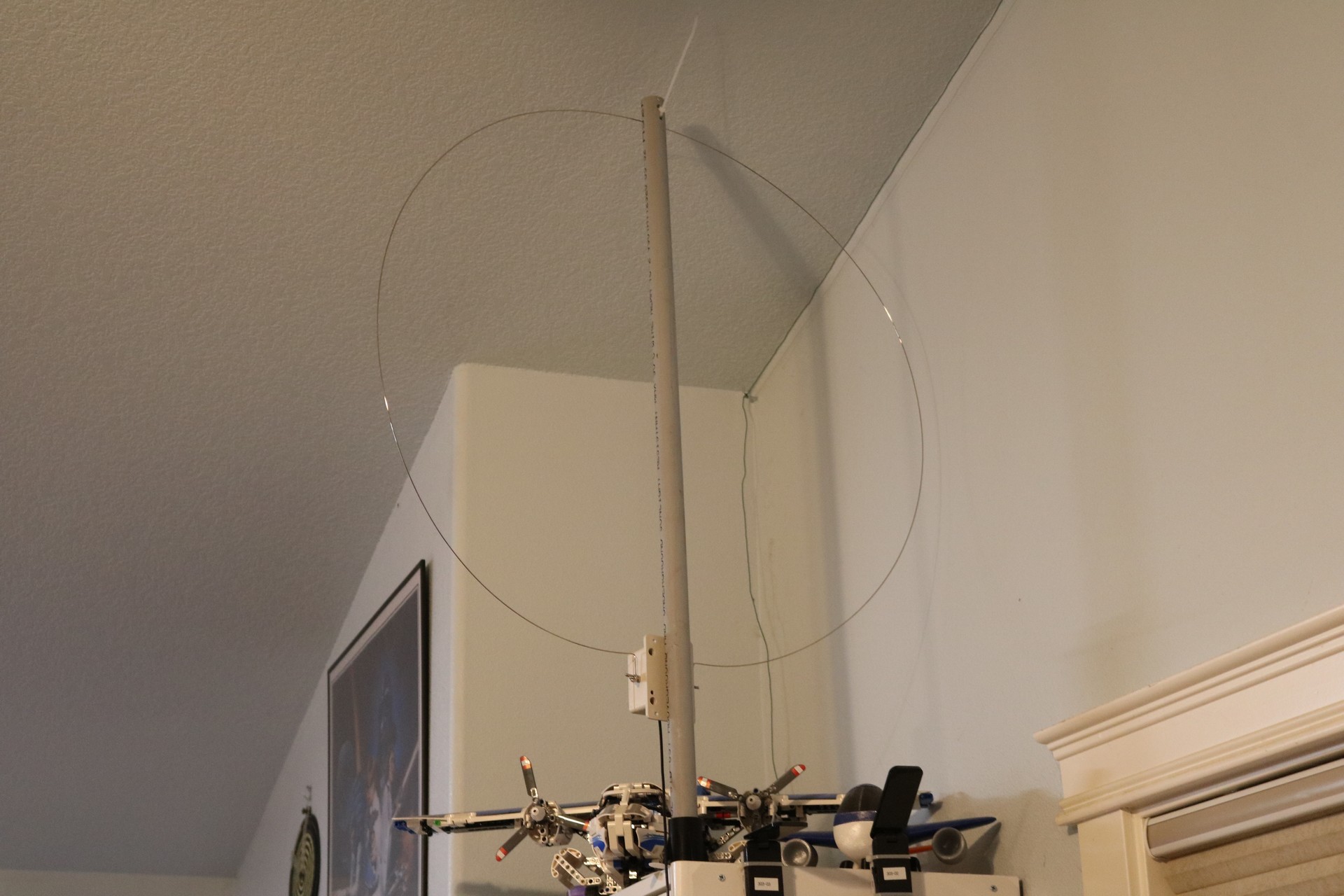
Third Antenna: The Youloop
Doing my online research, I stumbled across the youloop, a simple loop antenna, and I ordered a youloop clone from Amazon. I did this without realizing that a youloop is best suited for sensitive SDR radios and not necessarily the best choice for my 1983 heathkit special.
The youloop seemed to work altright. Maybe a little better than the random wire antennas. Or it might have just been wishful thinking
Fourth Antenna: The MLA-30+ MegaLoop
In parallel with ordering the youloop, I also ordered an MLA-30+. This is another loop antenna, but it’s one that includes a built in amplifier, right at the antenna itself. The MLA-30+ performed better than any other antenna I have tried to date. Whereas previous antennas were incapable of tuning the 5MHz band on the radio, this one did indeed pick it up. It also seemed to tune the 10MHz and 15MHz louder than the other antennas. This isn’t surprising, the inline amplifier seems to help a bit.
The GC-1000 Enigma Clock still would not reliably sync the time.
Recapping, Cleaning, and Fixing Things
In parallel with all of the antenna drama, I was little by little trying to replace or improve parts of the clock. Here’s a log of every single change I can remember making:
- Replace electrolytics on the main board. This step I did as part of the original repair.
- Repair the broken trace on the main board.
- Replace the wiring to the DC jack, which had previously deteriorated and separated.
- Replace the wiring to the RS232 DB25. It was frayed and about to fall apart.
- Spray deoxit in the slide switches for debug mode and for display on/off. These are poor quality switches and should really be replaced. Even after hitting them with the deoxit, they’re still finnicky.
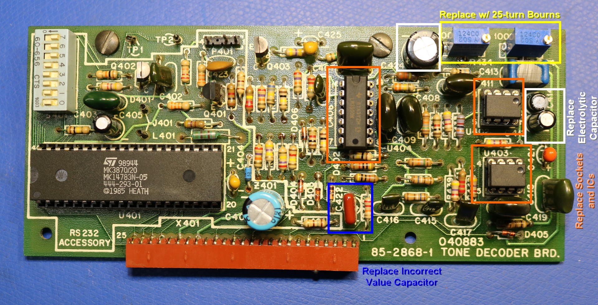
- Replace R434 and R444 on the tone decoder board with 25-turn potentiometers. First I wasted my time and used random China Ebay potentiometers. Then I came to my sense and installed name-brand Bourns pots from mouser. If you care about the accuracy of your pots, and if you care to not have them drift, but the name brand ones.
- Replace electrolytics on the tone decoder board. This included replacing C422, a 3.3uF electrolytic with an 0.33uF film capacitor. The manual says 0.33uF, but I found 3.3uF on the board. The incorrect part may have been part of a previous owners recapping, or it may be the documentation is wrong and that is the cap Heath actually supplied.
- Clean all board-to-board connectors. The pins you can clean with a pencil eraser. I also sprayed some deoxit inside the female housings.
- Reseat every single IC in the clock. The IC sockets are very poor quality.
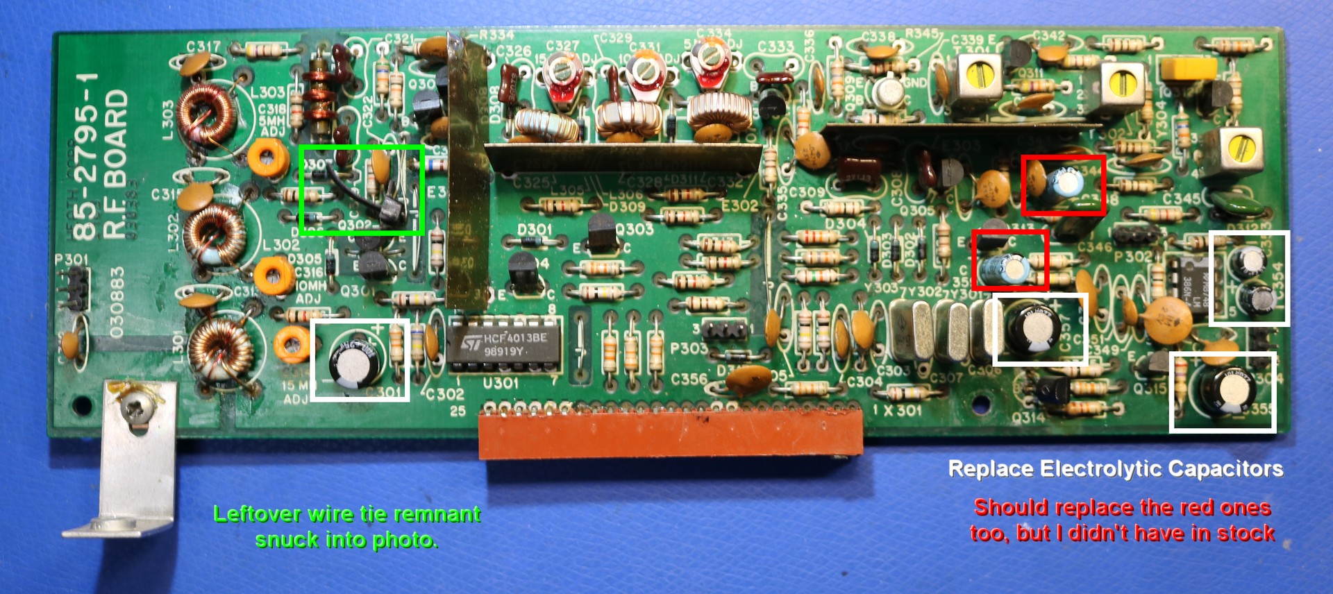
- Replace electrolytics C354, C353, C355, C357, and C301 on the receiver board. These parts you can probably replace without throwing the RF alignment completely out of wack.
- Replace IC sockets for the LM567 tone decoders and the LM3900 op-amp on the tone board with machine-tooled pin sockets.
- Replace the LM567 tone decoders and the LM3900 on the tone board with new nichicon caps from Mouser.
Success!
Right after replacing electrolytics on the RF board, and replacing the LM567 and LM3900 on the tone board, and performing yet-another-tone-board adjustment, the enigma clock immediately (while I wasn’t watching it, of course) synced with WWV, and as I write this paragraph of the blog post on a lazy Sunday afternoon, the enigma clock has been in hi-spec for a continuous two hours. It’s a new record.
I continued to watch the clock over the next week, and it remained in Hi-Spec mode approximately 85% of the time, day and night. It worked at various times of the day at 5MHz, 10MHz, and 15MHz.
If I was to guess, I’d say it was the IC sockets on the tone board. They were pretty nasty.
Monitoring the clock
I had such fun getting the clock working that I decided I’d like to collect data on it to see just how much I improved the performance. I would do this by measuring the duration that the hi-spec LED is lit. At the same time, I could watch the capture LED and the MHz LEDs to know which band it was listening too, day and night. I started by instrumenting the display board with some wires:
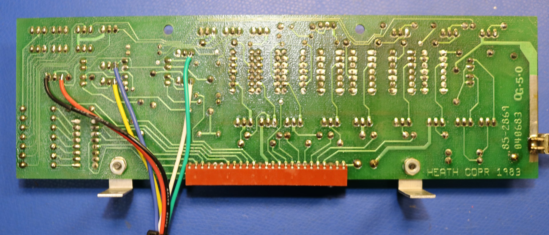
Once the wires were attached to the display board, I added an inline JST connector, and I ran the wires out the back of the clock through pins 14-19 of the DB25. These pins are generally unused.
I wired them to the DB25 as follows:
| DB25 | GC1000 Component | Function | Raspberry Pi |
|---|---|---|---|
| 14 | GND | GND | GND |
| 15 | Q124 | 5 MHz LED | gpio22 |
| 16 | Q125 | 10 MHz LED | gpio23 |
| 17 | Q126 | 15 MHz LED | gpio24 |
| 18 | Q127 | Capture LED | gpio25 |
| 19 | Q128 | Hi-Spec LED | gpio27 |
Then I build a hat for my Raspberry PI Zero W:
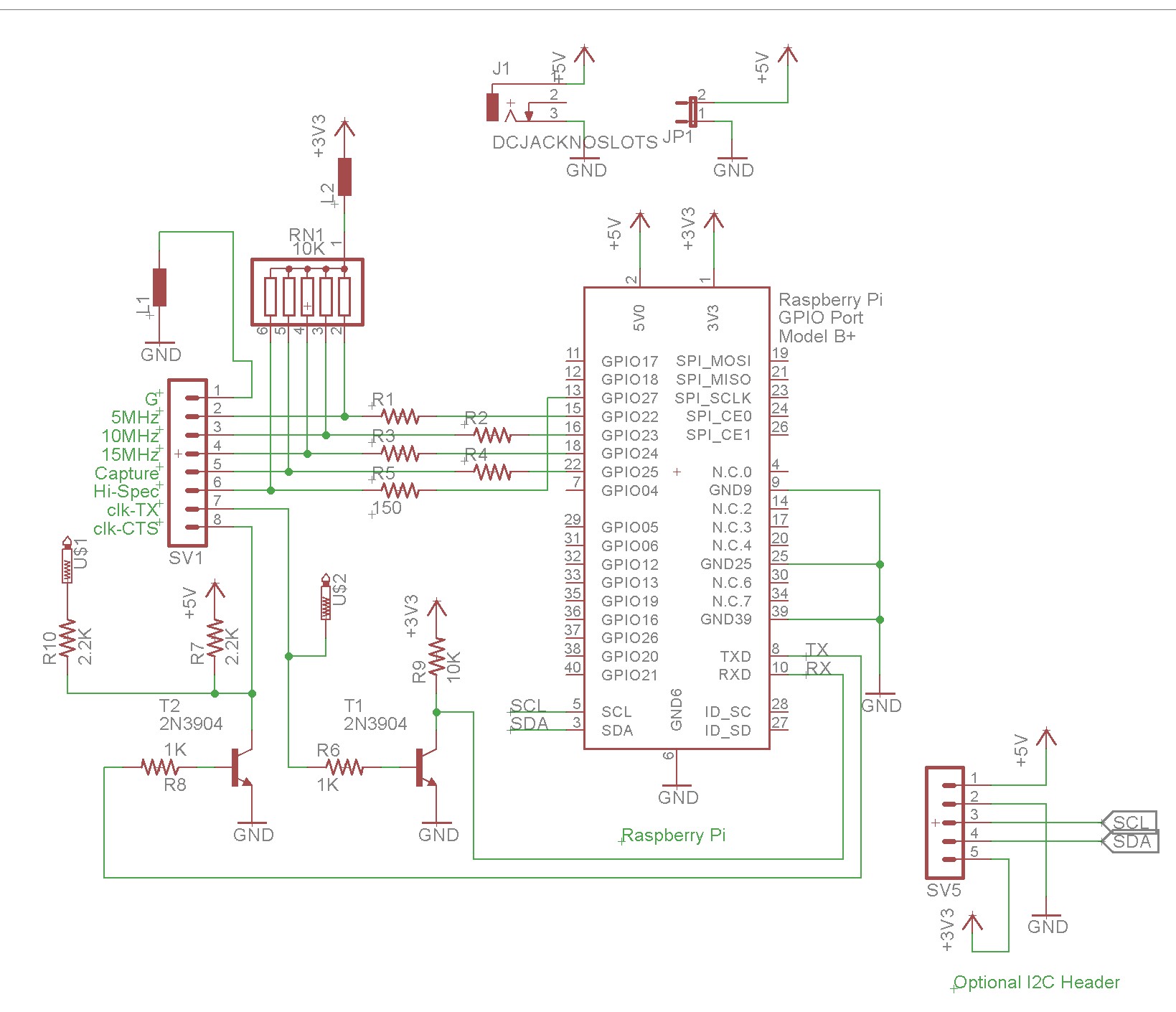
I used 10K pullups on the outputs from the clock, together with 150 ohm protection resistors to the pi, just incase of programming error. A couple of ferrite beads were thrown in to minimize any noise between pi and heathkit clock. The transistors are used for interacting with the GC-1000’s serial interface. While the GC-1000 does do RS-232, it does it in a funky way, setting up a “virtual ground” at +5v, and flipping the serial signals around the virtual ground, from 0V to 12V. It worked easily enough to just feed this into a transistor and trigger the PI’s serial RX line. The CTS signal was sent similarly, using a transistor to drive the CTS between +5V and 0V. I wasn’t sure it would work, but it did!
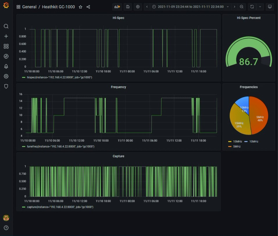
Below are some pictures of the results I collected, first, the MLA-30+ megaloop antenna:
Next, using my random length wire antenna, outdoors with the 9:1 unun:
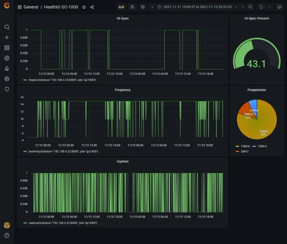
As we can see, using the Megaloop, I was in hi-spec mode86% of the time. Using the random length wire, I was in hi-spec 43% of the time. Either is a reasonable number, though the active antenna clearly does a bit better. It’s the 5MHz signal that is the discrepancy between the two graphs — the random length wire barely gets it at all.
Your’s is the first version of the test board. The 2nd version had a larger and better slide switch. It also had a good momentary pushbutton. The 1st version test switches are junk. It is the same as the display switch. This is a direct replacement https://www.digikey.com/en/products/detail/te-connectivity-alcoswitch-switches/1825079-1/14771105 I have a box of them.
Thanks Bob, I’ll have to order some of those!
The part number for the test(1st version only) and display boards switch is 1825079-1. It is available at Digikey, Mouser and Arrow Electronics. It is no longer being made. Get them while you can.
I’m sorry. I gave the wrong part number. The one I use is SLSA-220-1 by Alco. This may be it since the part number is listed by data sheet, but there is no data sheet to see. https://www.digikey.com/en/products/detail/te-connectivity-alcoswitch-switches/1825087-1/14799148
This will also work;
https://www.digikey.com/en/products/detail/cw-industries/GS-113-0512/1109?s=N4IgTCBcDaIM4HcCMAGMBaAdgExAXQF8g It is made by CW.
The length of the body has to be 10mm to fit in the slot for the display switch.
I’m curious how much drift there is between captures and between high-spec indications. (For that matter, how much does the clock wander *during* high-spec locks?)
It’d be interesting to compare the timing between the 1-second digit changes and the 1 pps signal from a GPS. There’d be some jitter, but the Raspbian gettime function reads to microseconds. You’d have somewhat lower resolution, depending on how fast a tight loop could check the status of a pin and run gettime or how quick an ISR could respond (much slower, I’d think), but even at a millisecond level, it would be interesting to see how much the clock wanders over time.
This is obviously far outside the clock’s use case, but it’d be interesting to see what the underlying level of accuracy actually is 🙂
The Heathkit GC-1000 clock has S401 DIP switches on the Tone Decoder Board. I have not found anything in the documentation on their function. Maybe I’ve over looked it in the docs, does anyone know?
Craig-those seem to have to do with the RS-232 “option” Could not find anything on them either; perhaps it’s in a different manual for the option
The ALCO Switch referenced by Bob (Nov. 11, 2021) is now Obsolete (October 2023).
Is the C&K “OS-series” Switch compatible?
https://www.ckswitches.com/media/1428/os.pdf
I see that the CW Industries slide switch,
GS-113-0512 is in stock at Digi-Key.