In this post, I add a panadapter to my Drake R-4B.
Background
In late 2021, I decided to become a Ham Radio operator. This involved passing a couple of tests — my technician and my general exam. It took a little bit of study, and soon being an amateur radio operator was within my grasp! I just needed a radio. As people familiar with my blog already know, I’m fond of vintage electronics, and I’ve done a couple tube projects in the past. So, I decided to buy a couple of “Drake Twins” on eBay.
“Drake Twins” typically refer to a pair of radios, a transmitter and a receiver. These can be operated separately, or they can be slaved together so the receiver can set the frequency of the transmitter and vice-versa. I purchased an R-4B and a T-4XC. Turns out I underestimated the amount of effort needed to repair the old rusty R-4B, so I ended up purchasing a second R-4B. Oops. Well the second one was in considerably better condition than the other.
Anyhow, restoring/repairing the radios is probably the subject of another blog post, so suffice it to say I managed to get them working. However, I found it hard to find folks to talk to. Maybe it’s my newness and lack of experience, or maybe it’s my lower-than-usual antenna, or maybe it’s poor band conditions, but would spend a lot of time searching for signals. This led me to jump into this panadapter project.
What is a “panadapter” ?
A panadapter takes a radio that is normally designed to operate within a limited bandwidth, typically 4KHz for AM , 2.4KHz for SSB, or 1.2KHz for CW, and adopts that radio to output a wideband signal. This wideband signal could be viewed with a spectrum analyzer or a software defined radio (SDR). The wideband signal allows you to “see the whole band”. The etymology of the prefix “pan-” may trace back to Greek, and generally means “all”. For example, “pandemic” is a disease occurring worldwide. Well, a “panadapter” is an adapts a radio signal to be band-wide. It could even be wider than just a single band.
So what’s the value of this wide-band signal? Well, by seeing the entire band at once, you can easily see everything that’s going on. You can see 2.4KHz SSB transmission, you can see 400KHz CW pulses, or you can see wide AM transmission.
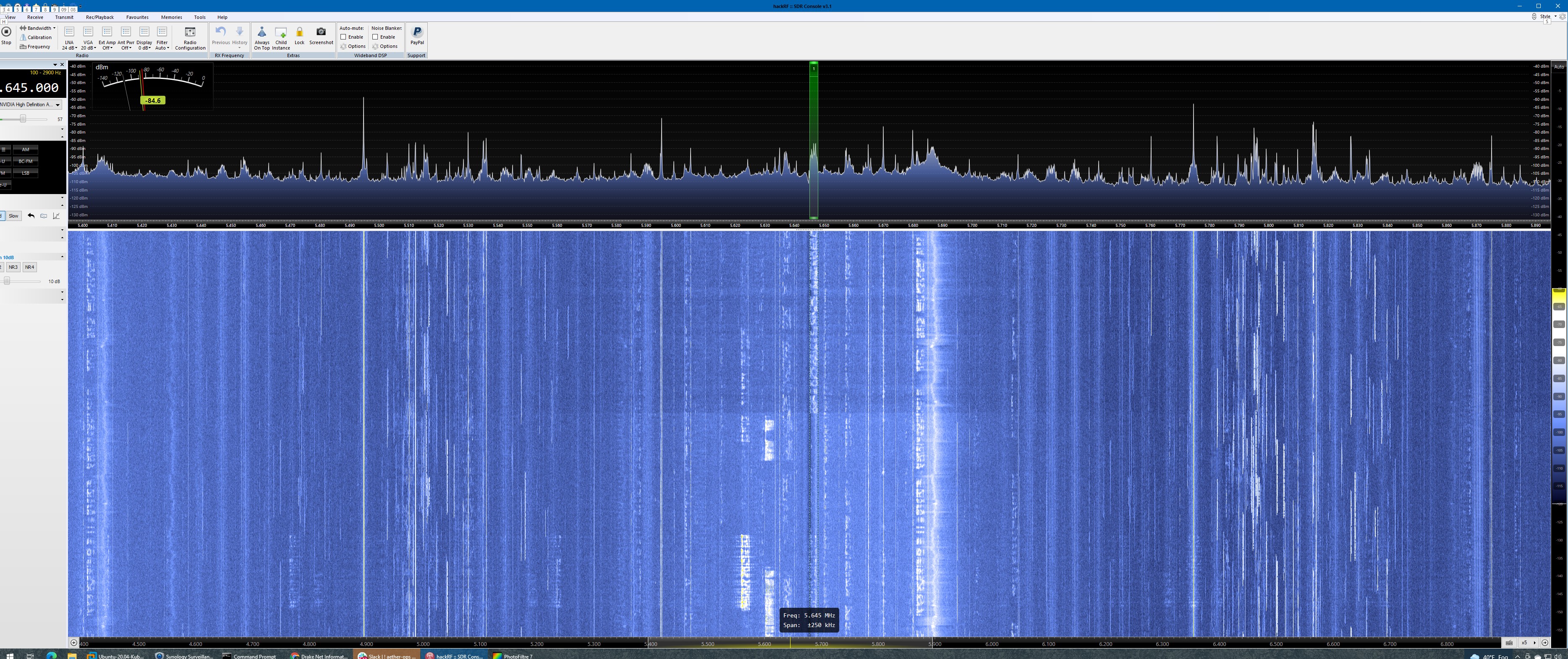
In the above display, the signal I’m tuned to is right in the middle, beneath the narrow green bar. That’s a 2.5KHz SSB transmission. To the left of it, you can see several more 2.4KHz SSD signals. On the right side, you can see many thin lines that might be CW or other digital signals. Interference/noise is also shown on the display, so you might see some wide wobbly noise signals.
The “waterfall display” continuously runs, with new data appearing at the top, flowing down the screen. My wife thought it looked like “The Matrix”. Well, sort of, not really. Anyhow, notice the two very strong pulses to the left of where I’m tuned — those brief signals could have been someone calling “cq cq cq” looking for a contact. Just spinning the dial through the band, you might well miss them. But the panadapter lets you see the whole band at a glance.
How do we make a panadapter?
First we need to understand a little bit about our ham radio. Our Drake is a double super heterodyne receiver. It takes the incoming RF and it mixes it with a desired frequency from a local oscillator, to center that frequency around an intermediate frequency (IF). In our case, this IF is 5645 Kilohertz. The reason this is done is because it’s easier to design filters and amplifiers around a fixed frequency than to design them around broadband. So it filters this 5645 KHz, and then it mixes it again down to 50 KHz, where it can filter and amplify it some more, and then finally a detector can covert it to audio. To make our panadapter, we need to intercept the signal right after the first mixer stage.
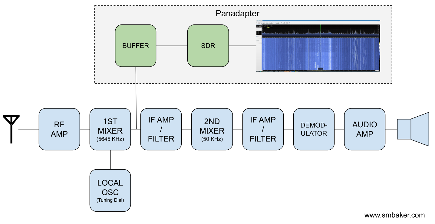
As you can see, we’ve added some additional components. The original radio pipeline is in blue. We’ve added some parts in green. These parts are a buffer, because we don’t want to overly load down the RF signal within the receiver, and a Software Defined Radio (SDR) dongle. Finally, we display the spectrum on our Windows, Mac, Linux, or other PC. You might be able to use something like a TinySA spectrum analyzer too.
The SDR Dongle needs to be able to handle the intermediate frequency from your radio. My Drake has a 5645 KHz intermediate frequency, but your radio may differ. Some radios have 9 MHz. Some radios have 455 KHz. Some radios have something else. Not all radios can tune these frequencies. For example, my rtl-sdr dongle does not. I have a “HackRF One” Dongle that does handle it. So choose your SDR wisely.
It’s important to notice that the frequency your SDR receiver will be centered around the IF. If you tune 7.238 MHz on the receiver, the SDR sees the IF (5645 KHz in my example). If you tune 28.5 MHz, the SDR sees the IF. As you tune your radio left or right, the spectrum is going to move to the left or right. Your tuning point will always be right in the middle of the display.
Building a buffer board
Now let’s talk about the buffer board. Here’s where life becomes a little difficult dealing with an old tube radio like the Drake. Tube radios are often high impedance signals. They’re meant to drive loads into the hundreds of kiloohms or even into the megaohms. If you take a regular garden variety amplifier designed for a 50 Ohm input impedance, you’ll suck the signal right out of your radio and there will be nothing. You’ll completely load down the receiver.
When I started this project, I originally tried Clifton Laboratories Z10000 Buffer from DX Engineering. I connected it to my 1st Mixer as above, and it rendered the receiver pretty much mute, because it drained all the signal. There was some speculation that an appropriate coupling capacitor might help, but really that amplifier board is not designed for a high-impedance input. It’s designed for modern solid state radios with a low impedance.
I asked for some tips in the Drake mailing list and was advised to use a high impedance FET Source Follower. I ended up using the following design:
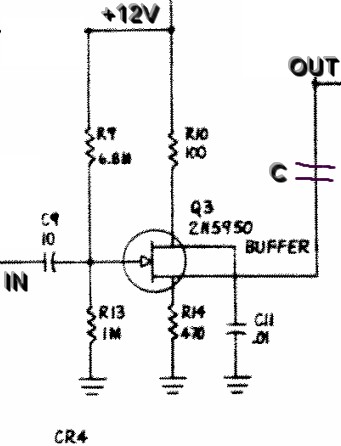
This doesn’t look like one of my own schematics, and that’s because it isn’t. I lifted this circuit right out of the carrier oscillator circuit from my Drake manual. The T-4XC’s carrier oscillator uses a 2N5953 for the oscillator and then buffers it using a pair of 2N5950 transistors. I grabbed one of the transistor stage schematics. The circuit is fairly simple. The incoming RF from the 1st Mixer is coupled by a 10pF capacitor. Then it goes through a bias resistor network, then it’s buffered by the 2N5950 JFET. The JFET’s “Drain” is connected via a 100ohm resistor to +12V, and the “Source” drives a 470ohm resistor to ground. We couple that out to the SDR through another capacitor (“C” in the above diagram, 0.001uF in my prototype)
I built that circuit using some proto-board and stuffed it into the drake.
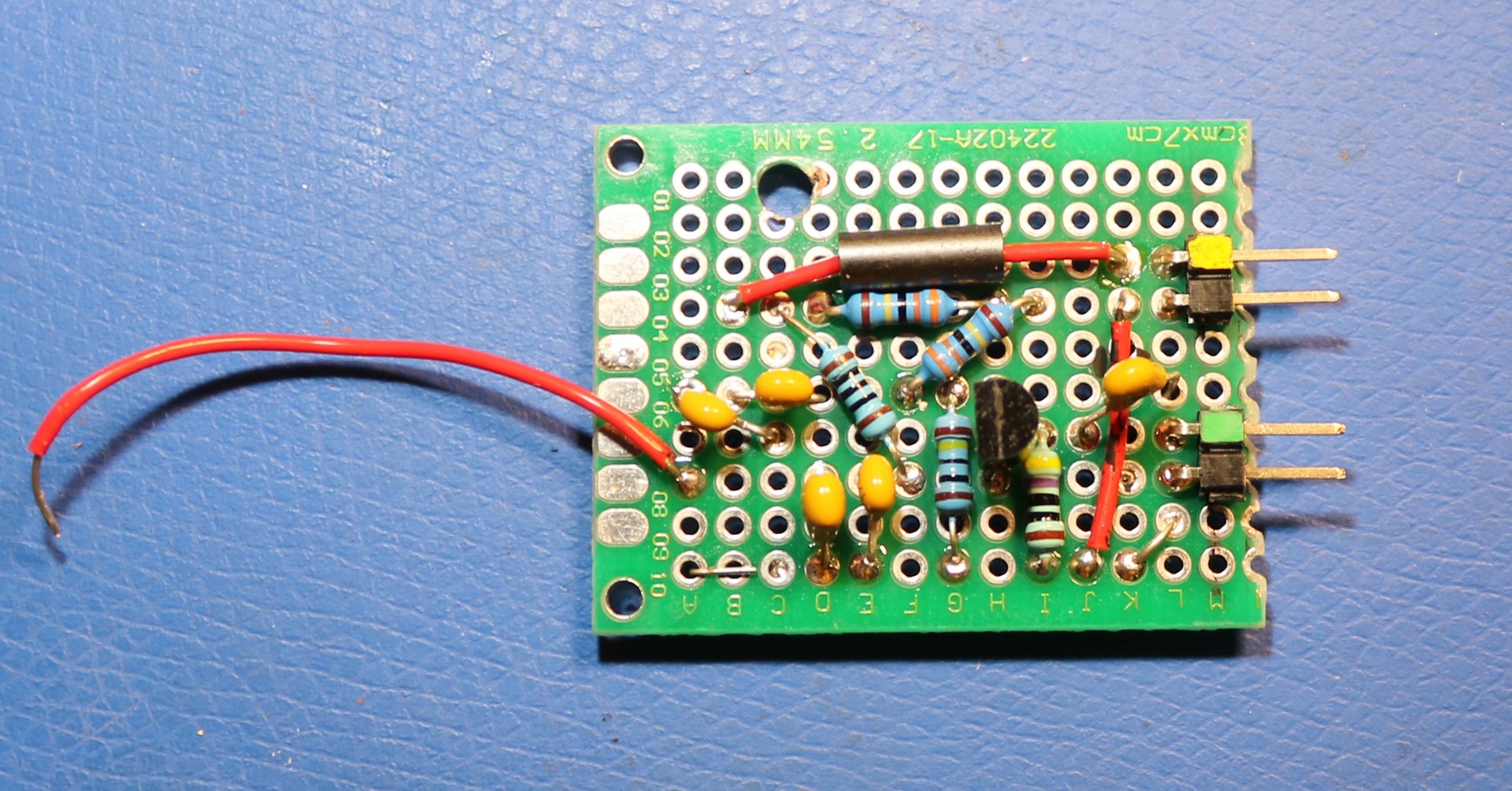
The single red wire is my input to the board from the receiver. I probably should have used shielded cable, but it’s short, and it didn’t seem to cause much trouble. The two 2-pin dupont plugs are for power (yellow) and signal out (green).
Prototype Installation
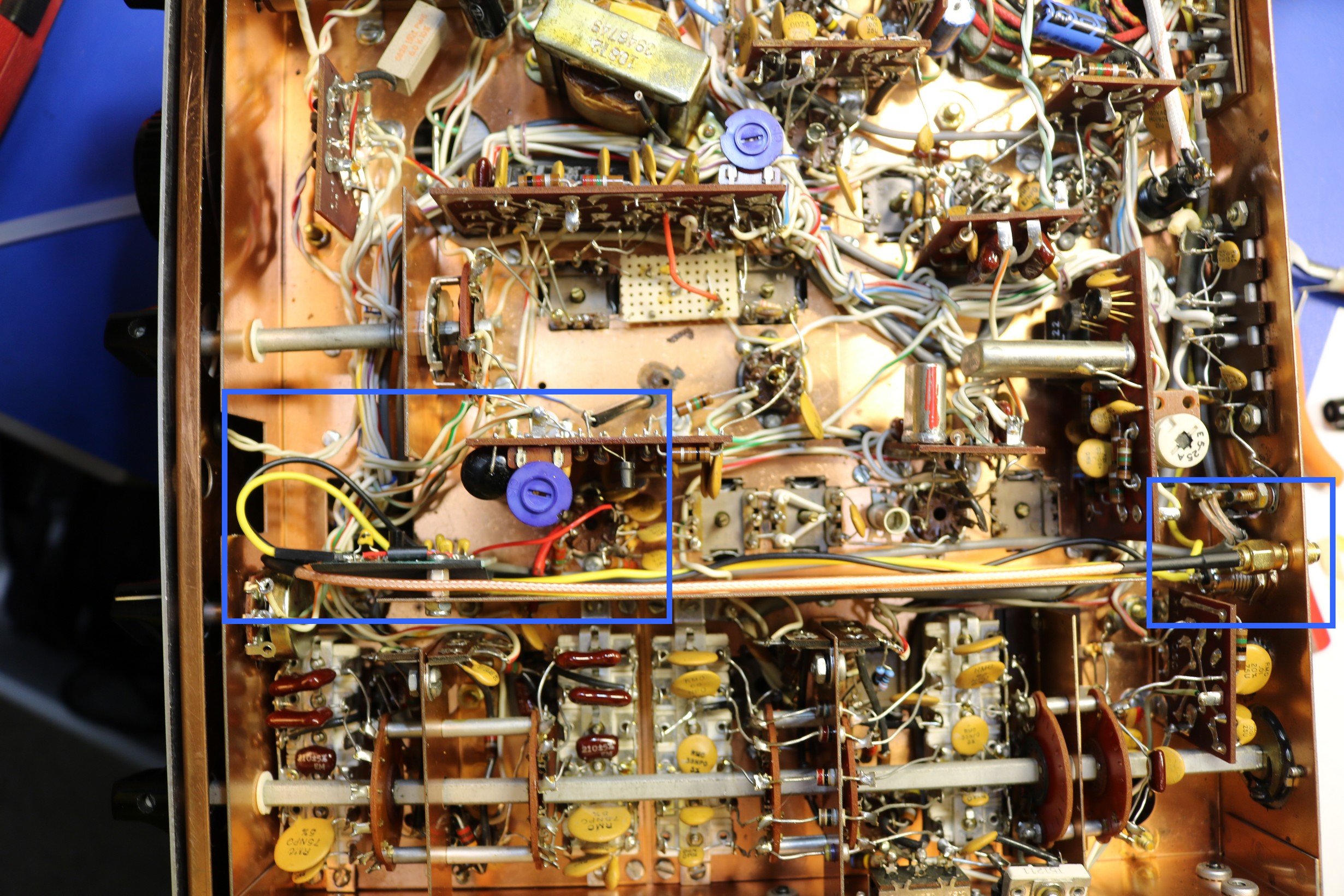
The board needs approximately +12V for operation. I got this by installing a diode and capacitor on the R-4B’s 12.6VAC filament supply. This forms a half-wave rectifier that will have somewhere around 14V to 18V on it, depending on the load. It’s not perfect, but it worked. Then I installed the board need V2, the first mixer. I connected it to V2 pin 5, and rand a cable out the back to an SMA connector:
My S-Meter does read low since adding the panadapter board. I do plan on experimenting a little more to understand this. It didn’t suck all of the signal outlike the Z10000 board did — the radio actually sounds really good after adding my FET Follower Buffer, it’s just that the S-Meter reads low. It’s entirely possible that I just need to retune the S-Meter sensitivity and offset. One really needs to do a realignment of the whole stage after altering the properties of the RF circuit.
Other Concerns
I had to install a hefty RF choke on the cable going to the SDR, or it would lock up whenever I transmit. It’s not the signal that was causing the SDR to be overwhelmed, I think it was stray RF on the coaxial cable. I use an end fed half wave (EFHW) antenna, and it throws some RF about.
Fantastic dr OM. I own 2 DRAKE C-lines, working still well. Inside/outside like new. Idea is to sell the stuff, looking for a newer radio. But I hate all the menu, hidden menu, etc. Sure, with the old RX I work like blind. So, the panadapter gives the possibility to see/control more or less the whole band range. R-4C is a triple, has another QRG anywhere in the 59… Khz. Can’t be a problem, I guess. I will try to build an adapter. Do u have experience using the line transceive?
Question is: How to connect to a PC or Monitor? Vy 73 !
Well, what a surprise to read all the work you were required to accomplish before hearing a voice. I am a retired Pharmacist. About 35 or more yrs ago I purchased a R-4B receiver and never did anything much but play it 2 or 3 times. Last Oct, I got my tech. License and now I am going to get my general soon. My R-4 B has been in a wrapped and enclosed, dry storage all these years. I am not able to follow your steps. I am 87 yrs old with Mac degen. Eye condition with oste arthritis. I have dealt with dr eng before and will probably deal with them. I plan on selling the R-4B if you are interested.
If you have the boards for the Panadapter made i would purchase several. I have both Drake and Collins receivers which would benefit from them
I have considered selling bare pcboards on ebay, like I do with some of my other projects. They would be bare pcboards only, not assembled, and no components.
What is the panadapter schematic you are useing.
Heathkit put out a panadapter for other frequences than there standard heathkits freqs.
K2DC makes a wonderfully small panadpter buffer board. Not only does it have a JFET source follower at the input but also an emitter follower at the output to drive low impedance loads. $22.
My concern is, how much BFO leakage do you see on your scope at 5645KHz?
Tnx,
Dale W4OP