I haven’t made a full video blog post yet, but here’s a 40 second video of the LEDs blinking:
Purpose
I’ve been doing a lot of work with the Heathkit H8 computer, and it’s common for me to want to connect a logic analyzer to the computer to sort out why my latest project isn’t working. But… it’s very inconvenient to reach down inside the computer to connect leads, so I decided I’d build a simple board that would breakout the bus pins at the top of the computer. I also decided that I would buffer these pins, so that attaching the logic probes or scope probes could not conceivably impact functioning of the computer.
I also added a pair of 74HCT688 and a set of dipswitches that allow me to decode a 16-bit address on the address bus. The reason for this is that most hobbyist and enthusiast grade logic analyzers are only 16 or 24 bits wide, and trying to decode an address can consume the entire logic analyzer. The pair of 74HCT688 allow you to trigger on a specific address with only one input to your logic analyzer
Once I did all that, I realized the buffered outputs would be perfect for driving LEDs, so I added a small daughterboard that attaches one LED to each output on the bus.
Schematics
The schematics run several pages, so rather than reproduce them here, I’ll point you to where you can find them in my github repository.
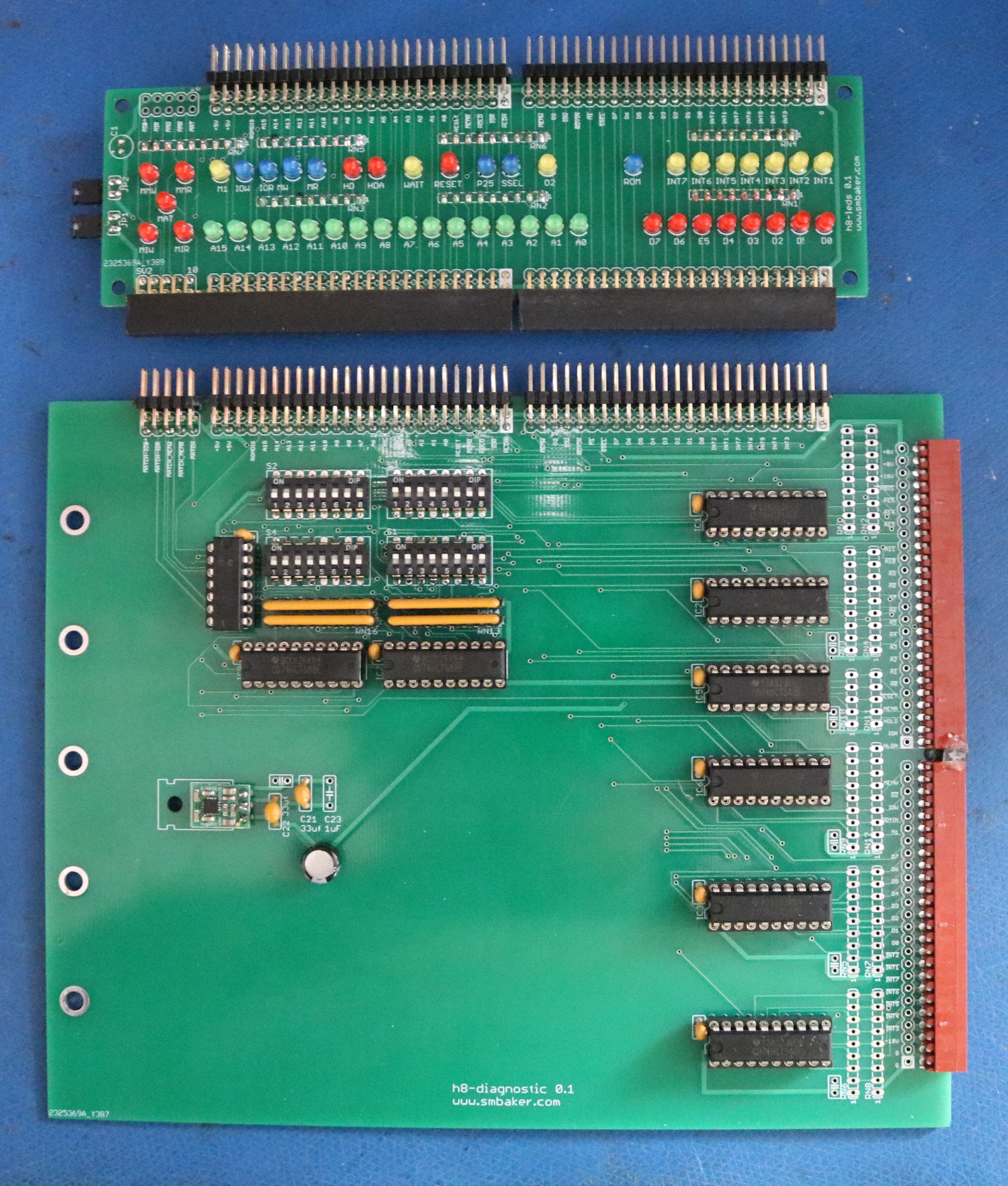
Implementation
The completed pair of boards is shown below.
Bill of Materials
Most of this can be ordered from Mouser or Digikey. Some things, such as headers or sockets, are most effectively purchased from eBay or Aliexpress.
Diagnostic Board
| ID | QTY | Short Desc | Long Desc |
| RN1-RN9,RN12 | 10 | 1Kx8 (9-pin) | optional 1Kx8 (9-pin) sip resistors, for bus termination (do not populate unless specifically needed) |
| RN10, RN11 | 2 | 1Kx4 (5-pin) | optional 1kx4 (5-pin) sip resistors, for bus termination (do not populate unless specifically needed) |
| RN13-RN16 | 4 | 10Kx8 (9-pin) | 10Kx8 (9-pin) sip resistors as pulldowns. Value is not critical. 1K or 4.7K also be fine. |
| unmarked caps | many | 0.1uF 2.54mm | Most of the ceramic caps that are not marked on the pcboard are 0.1uF monolithic ceramics. I’ll specifically note the ones that aren’t. Just buy a large quantity of these (bag of 100 or so) from eBay and have enough to last a while. |
| C19 | 1 | 100uF | 100uF electrolytic cap, shoot for around 10V or more. |
| C21, C22 | 2 | 10uF-33uF | Low ESR capacitor, such as a ceramic or tantalum. Something in the 10uF to 33uF range will do |
| C23 | 1 | 1uf | 1uF capacitor |
| H8 Headers | 2 | These are female right angle 2.54mm headers, for the H8 bus. There are numerous options, some out of production. You generally want two 25 pin headers. You can get by with two 20-pin headers and a 11-pin header from arrow electronics (part numbers 0022162200 and 0022162110) | |
| IC1-IC6 | 6 | 74HCT540 | Bus driver. |
| IC7, IC9 | 2 | 74HCT688 | 8-bit magnitude comparator. Optional, if you want the address trigger. |
| IC8 | 1 | 74HCT32 | OR gate. Optional, if you want the address trigger. |
| IC11 | 1 | 7805 | 7805 regulator, or use a pololu switching regulator |
| S1-S4 | 4 | DIPSW08 | 8-position dip switch. Optional, if you want the address trigger. |
| 2 | 25×2 Male | 25×2 RA male header. Suggest buying several 40×2 RA male headers and cut them to size. | |
| 1 | 10×2 Male | 10×2 RA male header. Optional, if you want the address trigger. | |
| 20-pin socket | 8 | DIP20 | 20-pin dip socket |
| 14-pin socket | 2 | DIP14 | 14-pin dip socket. Optional, if you want the address trigger |
| pcb | 1 | one pcboard, from jlcpcb or other |
LED Board
| ID | QTY | Short Desc | Long Desc |
| RN1-RN7 | 7 | 1Kx8 (9-pin) | optional 1Kx8 sip resistors, for LED current limit |
| LEDs | 49 | LED3mm | 3mm LEDs. Buy an assortment of diffused 3mm LEDs from Amazon, and you’ll have 4 colors to choose from (red, green, blue, yellow, clear) |
| C1 | 1 | 100uF | 100uF electrolytic capacitor, 10V or more |
| JP1,HP2 | 2 | jumper | 2-pin jumpers and associated shunt blocks |
| 2 | 25×2 Female | 25×2 RA female header. I had success buying 40×2 RA female headers from amazon, and cutting them. You can also make yourself 25×1 headers if you prefer (and not connect the row of grounds) | |
| 1 | 10×2 Female | 10×2 RA female header. I had success buying 40×2 RA female headers from amazon, and cutting them. | |
| 2 | 25×2 Male | 25×2 RA male header. Suggest buying several 40×2 RA male headers and cut them to size. Only needed if you want to be able to attach scope of logic probes to the “output” (top) side of the LED board. | |
| 1 | 10×2 Male | 10×2 RA male header. Optional, if you want the address trigger.Only needed if you want to be able to attach scope of logic probes to the “output” (top) side of the LED board. | |
| pcb | 1 | one pcboard, from jlcpcb or other |
Resources
- Github repo. Contains the schematics and the gerbers