In this post, I build a couple supercapacitor UPS boards for my raspberry pi projects.
Motivation
For my Convergent restoration, I decided to build an RASCSI to replace some failing SCSI hard drives. The RASCSI is a SCSI emulator built using a raspberry pi. Problem with these types of emulators is that if you carelessly power off the host computer (which was a perfectly acceptable thing to do back in the 80s), you end up also unsafely shutting down the pi — which can cause corruption of the SD-Card, loss of in-memory data, etc.
Back when I built David Gesswein’s MFM Emulator, he included a supercapacitor UPS that provided power just long enough to safely shut down a beaglebone. I figured the same thing would work for a raspberry pi.
UPS Basics
An uninterruptable power supply can serve several purposes:
- To provide resiliency when power brownouts occur. Sometimes power will be disrupted for a very short time, just long enough to cause a CPU to reset. A UPS can smooth out these brownouts and provide consistent power.
- For moderate time outages, a UPS can provide enough power to safely shut down the computer. Data is saved, corruption is prevented.
- For long term outages, a UPS can provide power that keeps the computer operational for the duration of the outage — you can keep working while the power is out.
For my use case, a SCSI emulator in a vintage PC, purposes (1) and (2) are valid, but purpose (3) is unnecessary. I wanted the RASCSI to be able to save its data properly when the power is cut. I have no need for it to continue working during a prolonged power disruption. I need about 30 seconds of uptime.
For this level of backup, a supercapacitor UPS is ideal. Supercapacitors charge quickly. Supercapacitors have a good lifespan over many charge/discharge cycles. The vintage computers I’m working on, there might be months between the times when I power the computer on — there’s no need to keep a battery charged during those months.
Basic Design for a 12V to 5V UPS
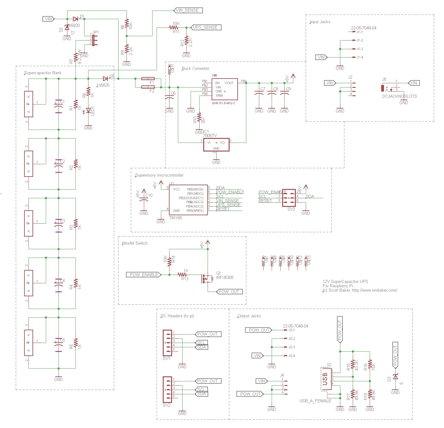
The supercapacitor bank is comprised of 5 capacitors each one 10F with a 2.7V rating. In parallel with each capacitor is a shunt regulator that limits the voltage on the cap to approximately 2.5V. This leads to an overall limit of approximately 12.5V, and any voltage across the capacitor bank in excess of that will probably be burned off by the shunt regulators as heat. The supercapacitors are charged by a 3W resistor — David Gesswein’s schematic called from an 8.2 ohm resistor, whereas I believe I used (and perhaps his BOM used) a 10 ohm. Either is probably in the ballpark. This resistor limits the rate at which the supercapacitor can charge. A jumper, JP1 allows you to either:
- Enable the capacitor bank by shorting pins 1 and 2
- Disable the capacitor bank by leaving the jumper removed
- Discharge (and disable) the bank by shorting pins 2 and 3. This is good for working on the circuit.
There are two diodes that control the flow of voltage. D1 prevents electricity from flowing back out the input. D5 prevents electricity from bypassing the current limiting resistor. A couple additional TVS diodes (D2, D3) are optional protections for transient spikes.
One of two voltage regulators may be chosen:
- U$6 is a murata DC/DC converter, OKR-T/1.5-W12-C, same one as used in David’s BOM.
- IC1 is a 7805 footprint, intended to be used with an EZ-SBC buck converter. EZSBC sells these neat little converters that are drop ins for a 7805. PSU5A is rated at 2.5A, and while I’ve used it in other projects, I have not used it here.
These voltage regulators supply power to not only the device (i.e. the Raspberry pi) being powered by the UPS, but also power to the supervisory microcontroller.
A MOSFET switch, Q1, is used as a high-side switch to control power to the device being protected by the UPS. This allows us to turn off the power when the battery gets low, and it allows us to force a reboot by power-cycling the device. It also allows us to prevent power from flowing on start-up until the batteries are sufficiently charged.
U1 is an ATTINY85 microcontroller that serves as a supervisor for the UPS. It constantly monitors both input and battery power via a couple voltage dividers. It supports an I2C interface so the host device (the raspberry pi) can check on battery status. It runs an internal state machine that progresses through various states (capacitor charge, power-on, power-loss, wait-for-reboot, etc). Code for this microcontroller is present in my github repo, linked at the bottom of this page. The microcontroller has an ICSP header so it can be programmed in circuit.
There’s a variety of headers and connectors for various functions. I tried to include both old-school 4-pin HDD and FDD connectors, as well as barrel jacks, and even a USB-A connector for power out.
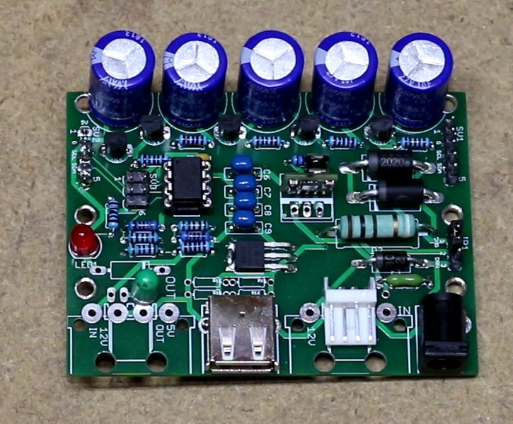
Implementation, 12V to 5V Supercapacitor UPS
Below is a picture of the PCB I had manufactured at jlcpcb:
Design, 5V to 5V Supercapacitor UPS
The 12V-to-5V UPS fit my need, but I figured, why not try to make this as a hat that I can use with a raspberry pi, directly, off of 5V?
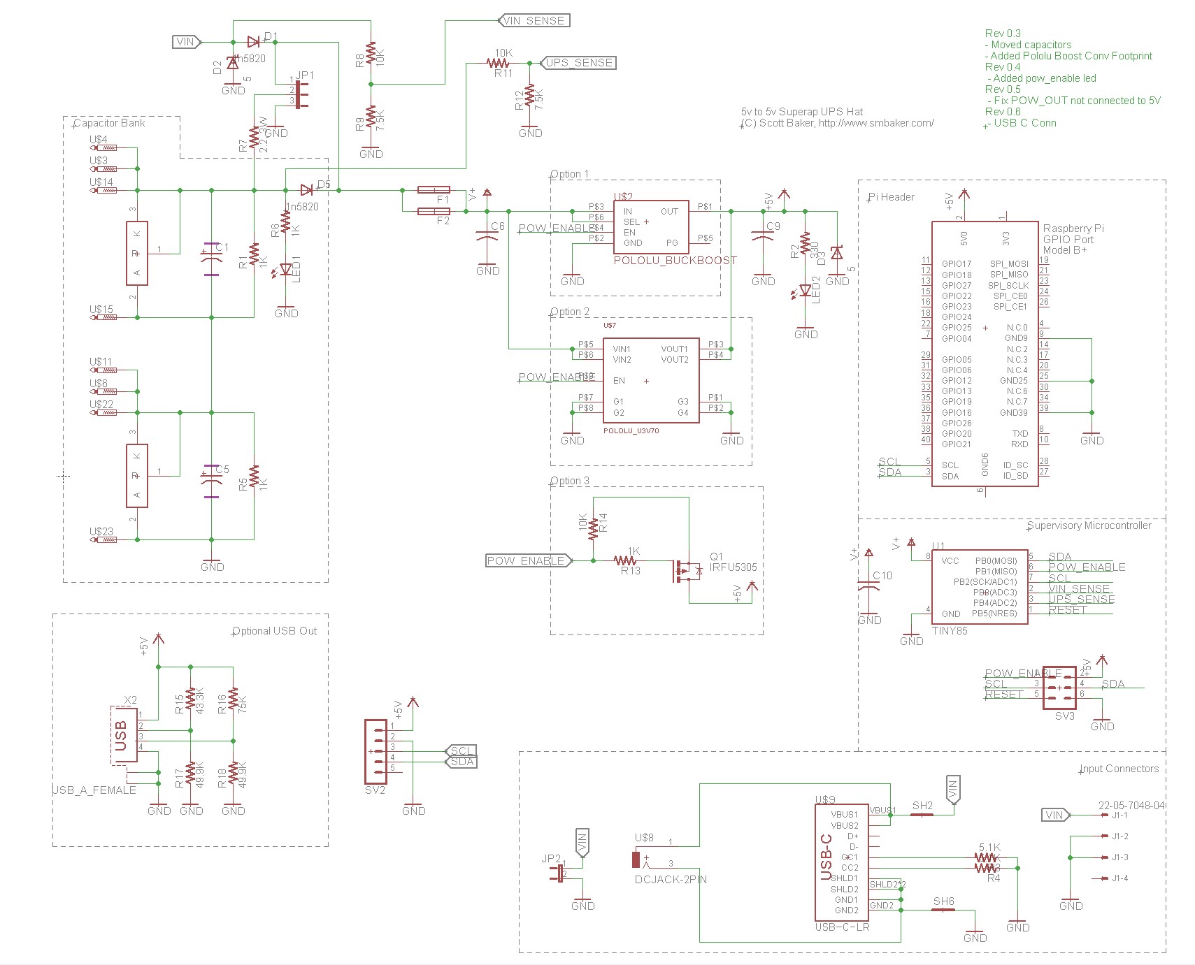
The overall design is similar to the 12V-to-5V UPS, with the following notable differences:
- Rather than 5 Supercap stages, there are just two. At 2.5V each, that allows us to store up to 5V of electricity.
- The microcontroller runs directly off of the input voltage / supercap voltage. The low-voltage version of the ATTINY85 tolerates voltages from 1.8V to 5.5V.
- The boost converter has been replaced with one of three options.
Boost converter options:
- The first option is a Pololu 1.5A buck/boost module. This was the option that I showed in the video. Having a buck/boost module is technically unnecessary — since the input voltage is a maximum of 5V, we never really need to “buck”, but only to boost. The MOSFET switch is not used with this option; we can turn the buck/boost module on/off.
- The second option is a Pololu 8A boost module. This is much better choice for trying to run a raspberry pi 4, since it can easily supply the 2.5A that the pi4 requires, and its efficiency doesn’t plummet as bad as the first option when the capacitor votlage level drops. As of 9/6/2020, I have not tried building this option yet — but it is my recommended design. I’ll update this notice once it’s been proven working. As with option (1), the MOSFET switch is not necessary, we can just turn the converter on/off.
- The third option is to use a MOSFET, without using a boost converter. This will lead to an output voltage that drops as the supercaps discharge. It might be useful for devices that are tolerant of a voltage range of 3V to 5V. One of my plans is to see how low I can power a raspberry pi before it fails and shuts down. This option is not recommended, but what the heck, it’ll be an interesting experiment.
Implementation, 5V to 5V Supercapacitor Hat
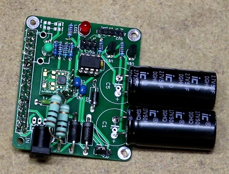
As can be seen in the video, this one didn’t quite pan out for me when it cam to powering the raspberry pi4. First, due to several factors (voltage drop on the power cable, voltage drop on the charging resistor, voltage drop on the diodes), we only charged the supercaps up to about 4.25V. This was enough with the 1.5A buck/boost module to boot up and operate the pi, but once we run off the batteries, it only takes about 10 seconds for voltage to drop down to about 3.4V, at which the buck/boost module start to have difficulty powering the pi (the buck/boost module becomes less efficient as voltage drops), the pi4 goes undervolt, and shuts off.
It did work fine on a pi zero w.
I am in the process of switching this module out for the 8A boost module, that I think will be more efficient at lower voltages.
Software
My github repo at https://github.com/sbelectronics/ups contains source code for both the microcontroller and for a python daemon that runs on the raspberry pi.
The python daemon continuously watches the input voltage, and when the input voltage drops, it runs /sbin/shutdown. Then, during the shutdown sequence of the pi, after the root filesystem has been remounted readonly, a systemd shutdown script will send an I2C command to the UPS to tell it to power off. The UPS powers off, and then waits for a power-up event (and supercap charge) before it’ll turn the pi back on.
Acknowledgements
- David Gesswein’s MFM Emulator was the inspiration for the 12V-to-5V module.
- TinyWireS was used to implement an I2C slave on the ATTINY85
Resources
- My github repo at https://github.com/sbelectronics/ups has the code.
- The library code (smb-pi-lib) is in a separate repository at https://github.com/sbelectronics/smb-pi-lib.
After adjusting the 5v to 5v do you plan on making a few to sell?
I’ll see how the revise 5v-to-5v turns out when powering a pi4. I’m not sure that I’d sell completed units (my time is too limited to manufacture them), but I could consider selling bare pcboards so people could build their own. There are already a few preassembled commercial products in this space a;ready (juice4halt being an example) but I don’t know how well those ones perform on a pi4 either — pi4 has higher current requirement than some of these products were probably designed for.
I would like to build the 12V UPS and wanted to ask which shunt regulators you used?
Are you going to share the PCB Design Files?
And thank you very much for this great documentation for this great project 🙂
Great experiment! I have been experimenting with a 12V power distribution board design thats gone through a few iterations. I too use to use isolation diodes, then moved to Schottky diodes for less of a voltage/power loss but have now moved to PMOS MOSFETS which have an even lower loss. Also have a look at ‘ideal diodes’ implemented with a MOSFET and dual transistors. I get a 39mV drop at 2A. Just for a bit of fun, you could have a INA219 current/voltage sensor reading the power usage of the RPi via i2C.
The shunt regulators were https://www.digikey.com/product-detail/en/on-semiconductor/KA431AZTA/KA431AZTACT-ND/3042486. I’ll look into sharing some of the board files.
I see you have a copyright on this page. Are you applying any specific license to this project? I would like to consider using it for work but without a compatible license we cannot use it.
@13:20 when the cap voltage is creeping up, I suspect that your volt meter is charging the super caps.
Thank you very much for sharing this project, it really looks great! I also had a glance at your code on github and tried to understand how things work. I have some difficulties with “from smbpi.ups import UPS, diags”, I don’t know “smbpi” and a search on google for “smbpi.ups” gave your project as a first result. Do you know where I can find more information?
The smb-pi-lib code is over at https://github.com/sbelectronics/smb-pi-lib. This is where I put a lot of my “common” code that is shared between projects. I’ll update the page to make this clear. Thanks for the comment.
Check the LICENSE.md file in the git repo for specifics, I’ve opted to go with Creative Commons Attribution-ShareAlike 3.0.
Do you have a BOM for the 5v to 5v please. I am hoping to build this for a raspberry pi zero W running some apa102 lights and all switched on/off with a light switch powering a 240 AC to 5v DC PSU so that when the PSU is turned off, the pi Zero W Shu’s down, and when switched back on reboots and either carries on from where it left off or restarts. Hoping to have both sound activated lights and just random pretty lights!
Can you provide more details of the components used in the 5V to 5V hat design and if possible the full circuit details as would like to build this or a slight variation on it. I believe this design if fantastic and exactly what I am looking for. Thank you for what you have shared so far it is great.
I like the idea of using the shutdown script sending a message back to the UPS to tell it to drop power. Could you give a summary of the protocol between the Pi and the ATtiny85. e.g. how does the Pi request info from the UPS, what are the various responses from the UPS?
Alternative idea: use an off the shelf pass-through battery pack, to power the Pi. Those are rather cheap and bigger ones could even power several Pi’s. Then the ‘only’ problem becomes detecting power loss to the battery pack. I have been searching a simple and cheap solution. Maybe something like a simple hall effect (https://www.google.com/search?q=hall+effect+switch+circuit+diagram) to signal the Pi’s
Hi,
Please ignore my previous question . As suggested I refered this link for TinyWireS header file –
https://github.com/nadavmatalon/TinyWireS
But when I used this file. I am getting below error
Error Start
———————————
‘REFS2’ was not declared in this scope
Error End
————————————–
Thanks Scott for sharing this project, I agree that supercapacitors have an edge over batteries for certain applications.
I would like to develop a a similar module but with an input voltage of 24V. Is there a theoretical or practical limit to how many supercaps you can stagger in series using the simplified shunt regulator approach for balancing (I would have 9×2.7V caps)? I’m trying to find information on what could go wrong, but haven’t been very successful.
PS I’m aware there are specialised IC’s for managing banks of supercapacitors, but that would be overkill for my application.
Many thanks
Hello, Nice article! Could you please describe how did you design the supercapacitors? Obviously the 12V and 5V level is necessary, but why did you select 10F and 50F on the two design? How much time does the PI needs to shut-down, and how does it discharge the capacitor?
I am wondering can it be implemented with smaller caps if the linux app react fast enough?
Thanks for your answer in advance!
Hi, finally I found a UPS / solution which will fit my demands.
But, how Rob already asked – Have you a BOM for the 5V version, especially the capacitors?
In the 12V picture are 5x 10F to see and the 5V seems to have 2x 50F in one picture – so the 12V has 2F overall and the 5V 25F?
Thanks for your answer.
Hello Dr Baker,
Thank you for sharing your design! I’m working with Raspbian Bullseye and it seems wiringpi, python-smbus and python-pip are not available. Is there any chance you will be updating your repository to be compatible with the latest Raspbian release?
Thank You
Hi, thanks for this job, it’s very useful.
I see that there is no answer since two years but if you are still there it would be very helpful to have answer to Rob’s and Tom’s questions !
Please give us an answer :’)
Hello
I am working on the Pi 4 and working on the UPS for safe shutdown. I have though the same solution as you but with a much simpler design which is connect the 5.5v superCap parallelly with the 5v raspberry input. But I feel it is a little unsafe so I found this. Thank you so much for the design. Very useful.