In this post, I made some wireless sensors, using BME280 temperature, humidity, and pressure sensors, together with SYN115 transmitter modules. I used these to verify the storage of vacuum sealed “PrintDry” 3D filament storage containers.
Purpose
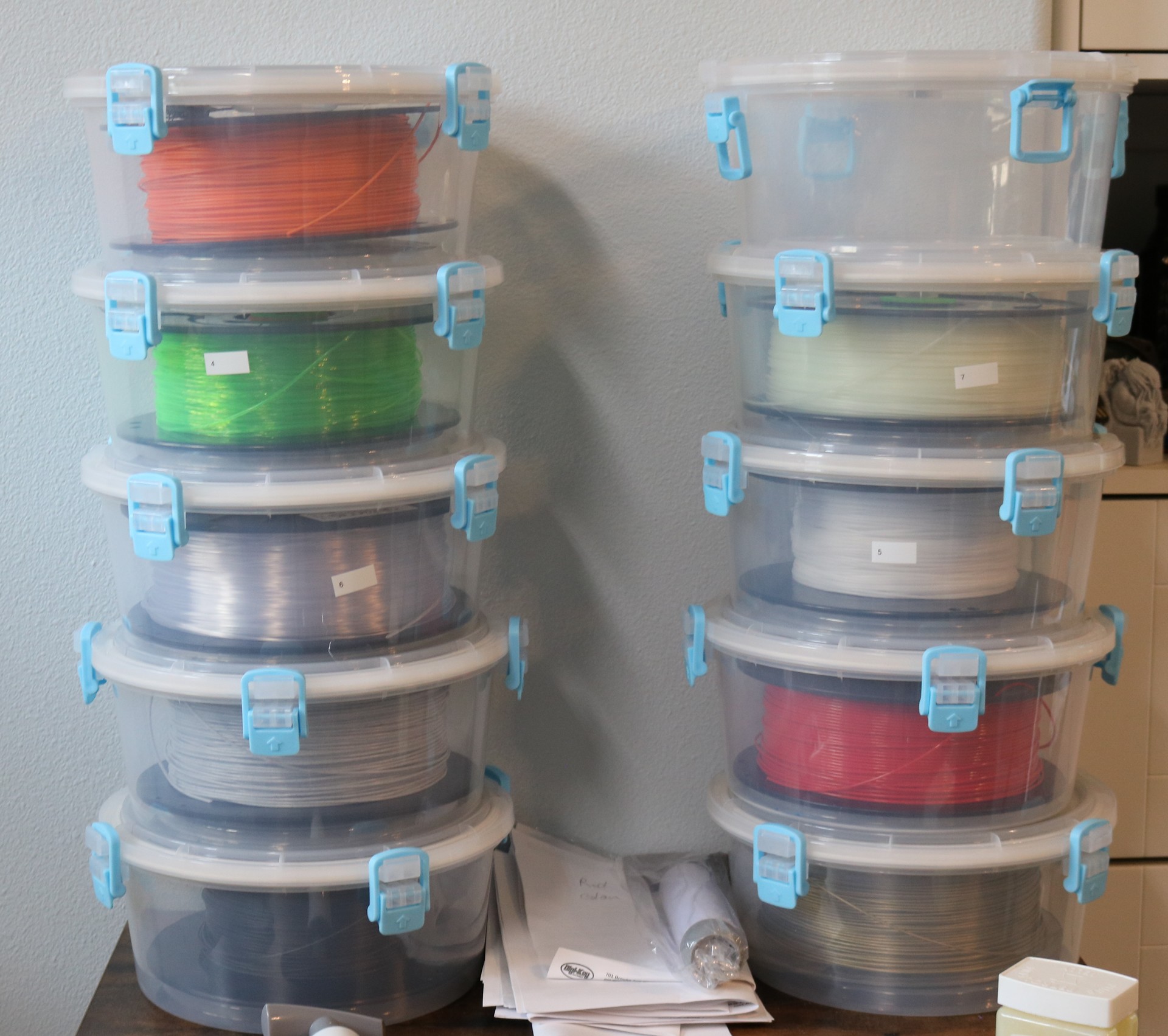
I bought some PrintDry vacuum sealed containers on Amazon. These are high-end containers, costing about $20 each. Yes, that does cost more than some spools of filaments, but realize a container may last forever while the filament itself is a consumable. The reason I chose these containers was primarily the size, durability, and quality of seal. I had been using “airtight food storage containers” prior to this, and while they work, they were a little oversized and I had my doubts about the integrity of the seal. The PrintDry containers, on the other hand, are designed especially for 3D printer filament. They’re just the right size for holding a 1KG spool. They’re made out of thicker plastic than the food storage containers I had been using.
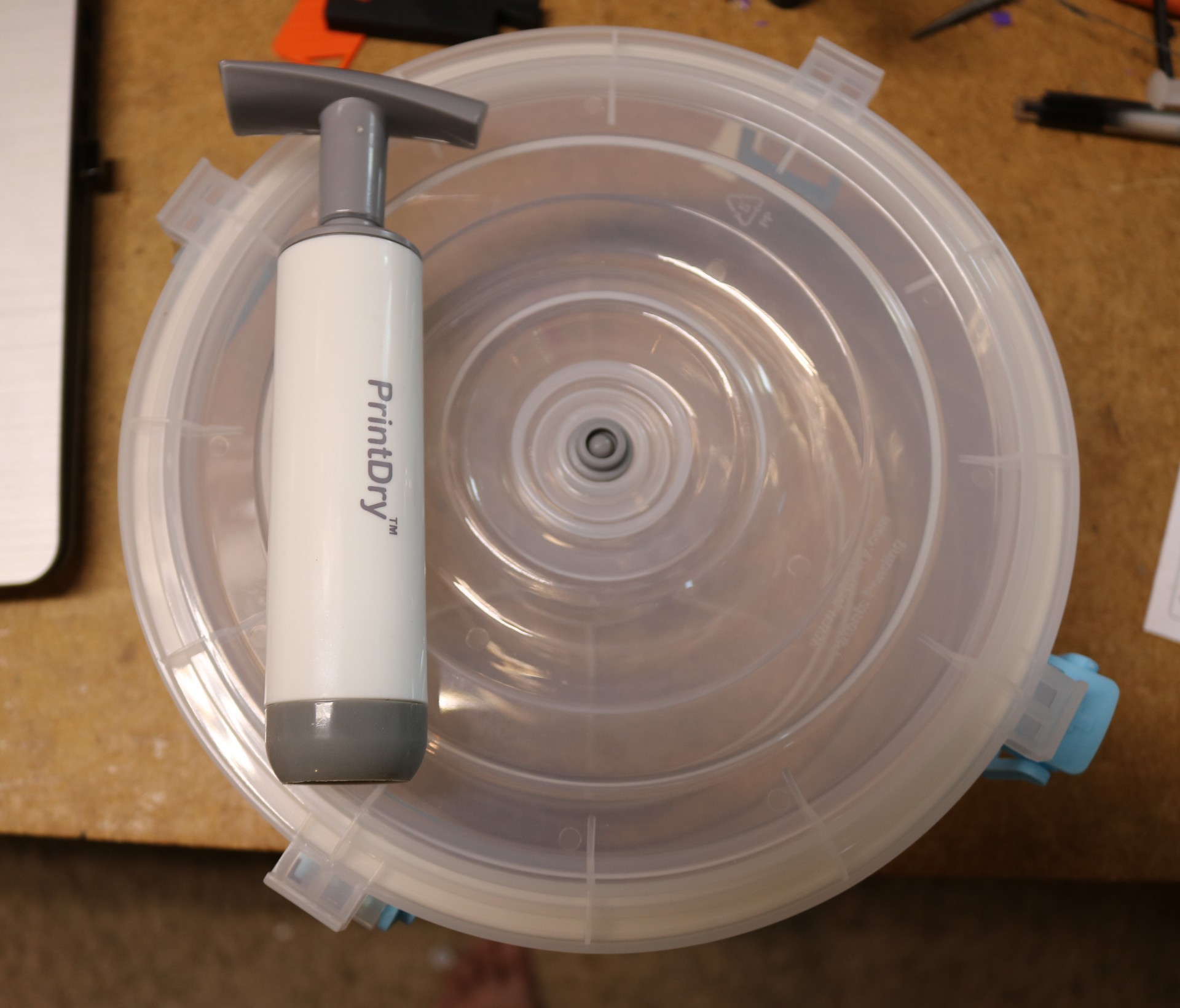
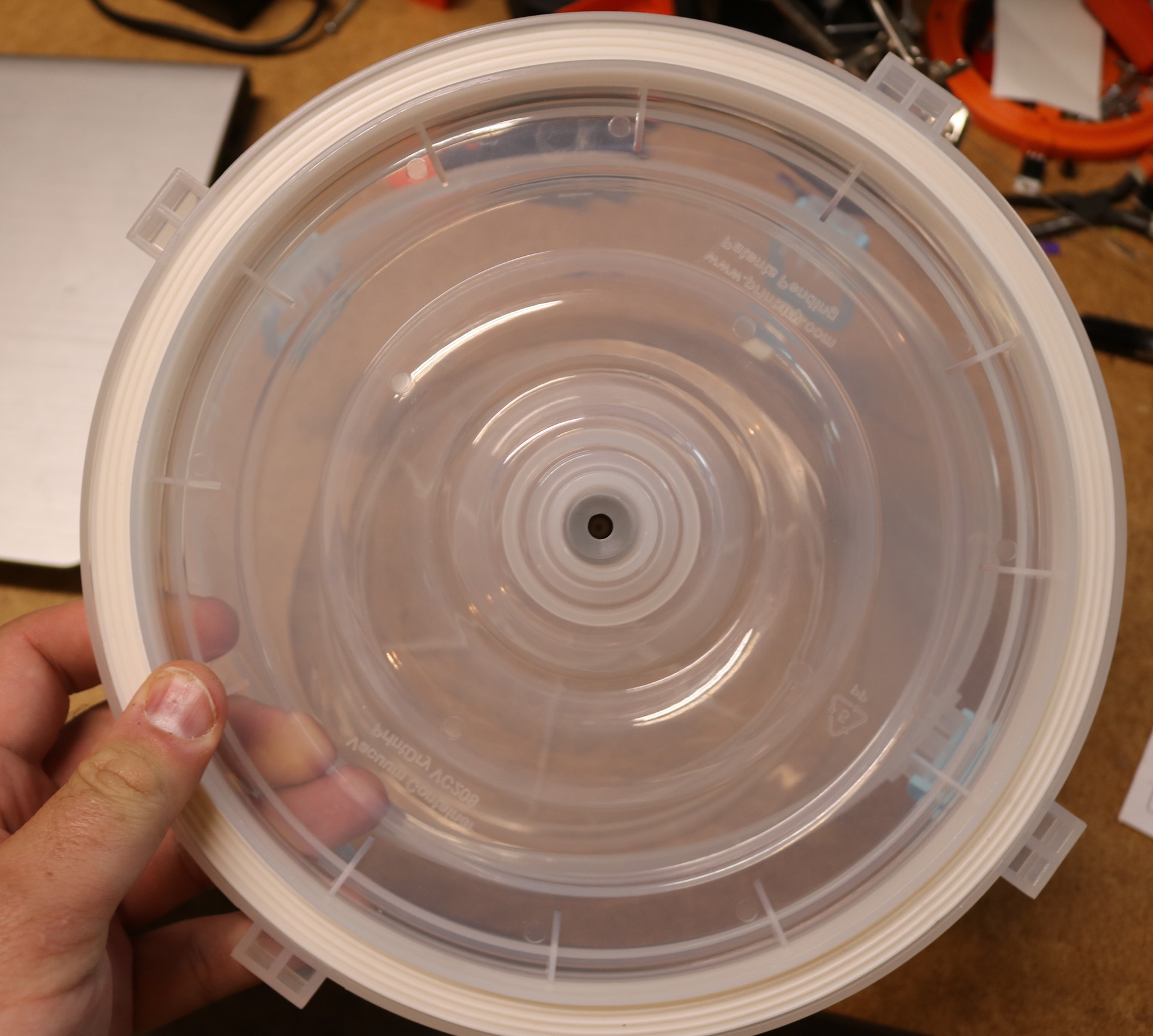
An additional benefit of the printdry containers is that they are vacuum-sealed. There’s a small rubber valve on top of the container that one attaches a pumping device to. You give it 5-10 pumps and it is supposed to achieve and maintain a vacuum inside the container. We’ll get to what we mean by “vacuum” in a bit. Here’s a picture of one of the containers and the seal used in the lid:
These containers worked great, except for the vacuum seal. I found that two out of the five in my initial order could only hold their vacuum seal for a day or two. Customer support from the manufacturer advised me remove the rubber seal from the container, clean the plastic flashing, apply some Vaseline, and reassemble it. I did this and got one of the two misbehaving canisters working fine. The other one I gave up on. Thinking this to be a fluke, I eventually ordered more of the canisters. In my second order, not one of the five would hold vacuum for more than an hour. Contacting customer support and complaining again, they advised me to do the same thing, which I did, and got all five of the second batch working.
I think that leaves me at 9/10 working correctly, and one from the original batch still not holding vacuum. I need to revisit that one; I bet I can get it working too.
However, while going through this exercise, I realized that it would be really handy to have some kind of active monitoring system for all of my storage containers, both the PrintDry containers and the food-storage containers. This would allow me to keep track of the pressure (to ensure the seals were not leaking) and the humidity (to ensure the desiccant was still active). I looked on Amazon, but couldn’t find what I wanted for less than about 60 bucks. I set a goal of doing it for six bucks.
Requirements
Here are the requirements I set out for myself:
First, the price needs to be in the range of six bucks or less. I have almost 20 filament canisters at this time and even a few rolls of filament in ziploc backs. At $6 each, that would be $120 worth of monitoring sensors. Seems like a reasonable investment.
Second, the sensors need to measure barometric pressure and humidity. Barometric pressure is important to verify the integrity of the seals on the PrintDry containers. Humidity is important to ensure that the desiccant is still performing as expected. Ultimately, ensuring humidity is the goal that’s truly important, since we’re trying to keep the filament dry.
Third, it needs to be battery powered and the battery life needs to be at least 6 months, preferably several years as I’m lazy and hate to change batteries.
My first prototype
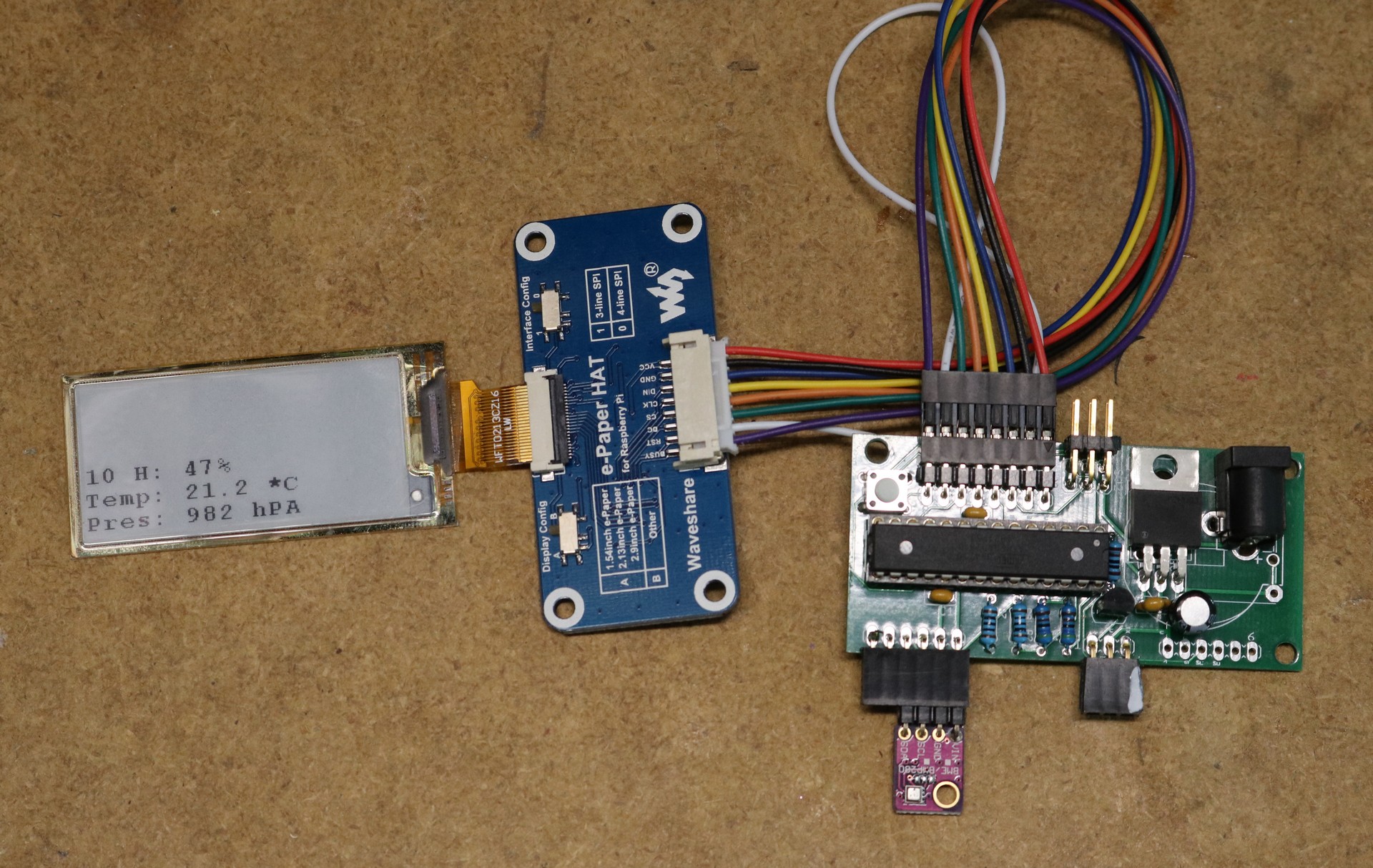
My first prototype is pictured below:
This prorotype used a waveshare ePaper display. I had previously used these displays on other devices. The prototype you’re looking at above wasn’t even plugged in when I took the picture — one of the advantages of ePaper is that it holds its image even without power. This prototype had a number of problems:
First, the display consumed too much power. The breakout board has level shifters and other logic attached, and I think it was that logic that was consuming the excess current. To make the battery requirement, I need to be in the range of approximately 5 microamps standby current. This prototype was consuming 300 microamps standby current (note for current measurements, I had another version without the onboard 3.3V regulator seen above, that I powered directly from a 3.3V source). To resolve this, I may have had to re-engineer the breakout board.
Second, the display was both inconvenient and unattractive to refresh. The atmega328 I was using did not have enough memory to hold an entire frame buffer — we’re so used to having a surplus of RAM on modern computers that sometimes we forget microcontrollers have a relatively limited amount of RAM. I’d have had to either get partial refresh working or implement a character buffer instead of a pixel buffer. Refresh was ugly, having many flickers between black and white. I believe the above display is supposed to be capable of partial refresh, but I couldn’t sufficiently bend the arduino code to my will to make this work. It’s possible with some time investment I could have got partial refresh working.
Finally, it cost too damn much. I was actually looking at a smaller board, 1.54″ for production, and even that smaller size I was looking at $7.50 for the raw display, or $20+ for a display plus breakout board. That totally blew the budget.
Let’s go wireless and display-less
The first prototype was a failure for many reasons, so I stepped back and thought more about the issue. Truth be told, I really didn’t want a display in each filament canister anyway. What I wanted was to be able to transmit the sensor readings to a receiver and have the receiver aggregate the readings and report them on a display. The receiver could also generate alerts if a sensor was outside of expected state.
I investigated wireless transmitters. In the USA, the 315Mhz and 433Mhz bands are both “unlicensed” and there are transmitters available, both from reputable dealers like Adafruit, Sparkfun, and Digikey as well as from various eBay and Amazon resellers. I eveluated both 315Mhz and 433Mhz modules and found that the 433Mhz modules interfered with my Somfy wireless shades. 433Mhz is also known to suffer from interference from (and cause interference on) nearby amateur radio bands. So, 315Mhz it is.
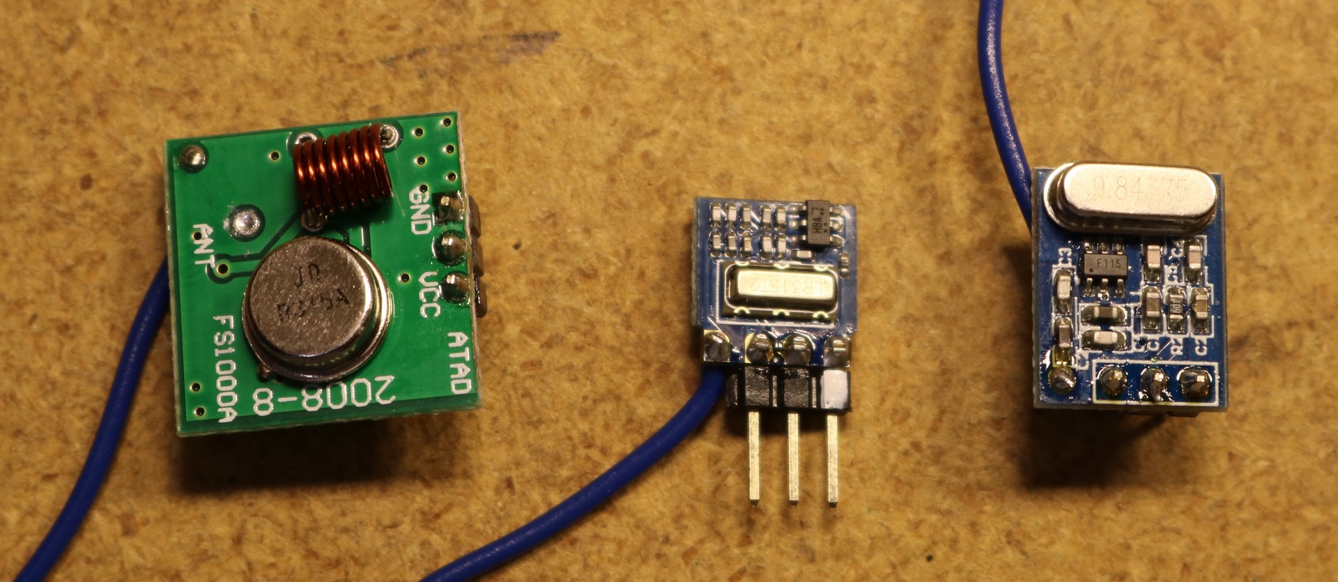
I evaluated three modules:
From left to right above we have the FS1000A, H34A, and SYN115. My FS1000A batch purchased from Amazon suffered from 50% of the modules being off frequency by various amounts up to 200KHz. The off-frequency modules had a resonator marked “R315a” whereas the on-frequency ones had a resonator marked “R315”. I suspect it was a batch issue, or possibly that a manufacture had used quality control rejects to assemble the modules. The FS1000A is also the largest modules of the ones I looked at, slightly bigger than I wanted.
The H34A suffered from mediocre range at 3V. Some sources cited these modules as requiring 4.2V, others cited them as requiring 2.6V. Regardless, performance at 3V was unacceptable.
That left the SYN115. This is specifically a low-voltage module operating at 1.8V to 3.6V. Perfect. I tested them, and the range was adequate, with reliably transmission from one side of my office to the other. SYN115 it is.
Sensor selection
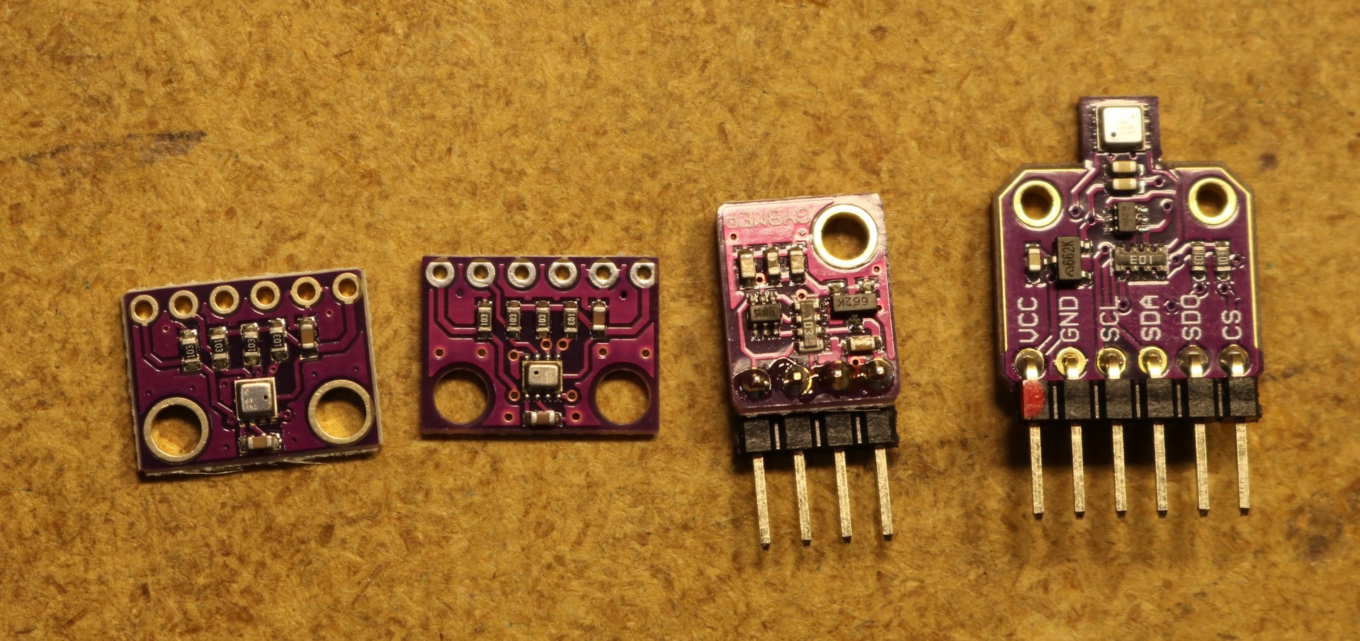
Pictured below are three different sensors:
From left-to-right above we have BME280, BMP280, BME280-5V, and BME680. Beware of the BMP280 as it lacks humidity and eBay sellers will falsely claim to sell you a BME280 with humidity but you will receive a BMP280 without humidity. Also watch out for the narrower BME280-5V board pictured above. It has level converters and voltage regulators and will consume excess current. The BME680 includes a gas air quality sensor, which is cool but requires power to run an onboard heater, making it not viable for battery operation. You can disable the heater, but then you’d be overpaying for features you don’t use.
Buy the BME280, and make sure it’s the 3.3V board, not the 5V board.
I should also mention that I could have purchased just the BME280 ICs rather than breakout boards, however the sources I found for BME280 ICs cost more than the complete breakout boards. Plus it’s a tiny thing that will be a nuisance to solder.
The final prototype
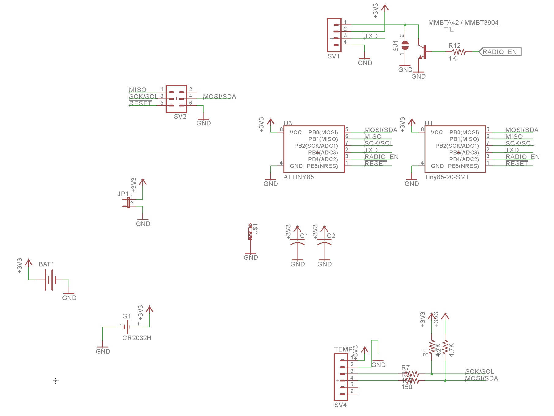
For the final prototype I went with an ATTINY85 for the microcontroller. It’s a small microcontroller that I can get in SMD. Schematic is pictured below:
The circuit is dead simple. You’ll see two ATTINY85 footprints — one is SMD and the other is through hole, of course you only use on or the other not both. There are some decoupling caps. The BME280 header has pullup resistors on the I2C lines, and it has protection resistors on them when they go to the sensor. I did this because these lines double as the ICSP programming connection. There’s a transistor that can be used to switch ground on or off to the wireless transmitter — I was a bit paranoid about standby current on the transmitter. Turns out the SYN115 has an automatic shutdown, so no fancy power switching is necessary. I omitted the transistor.
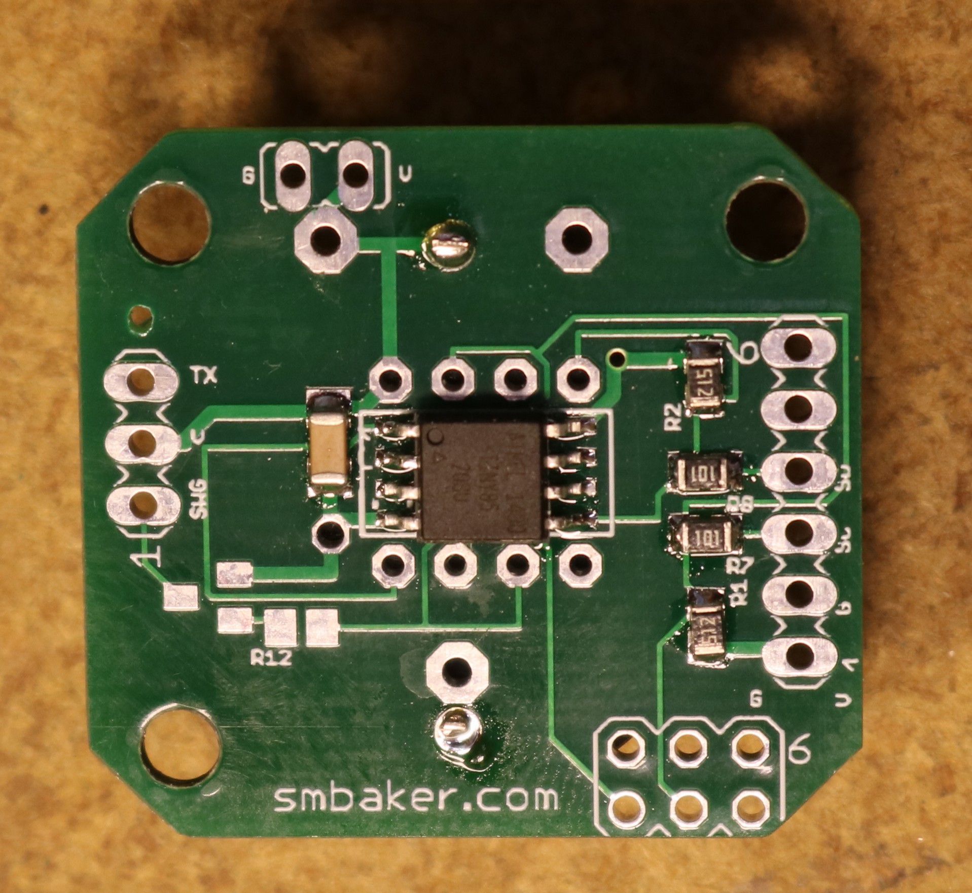
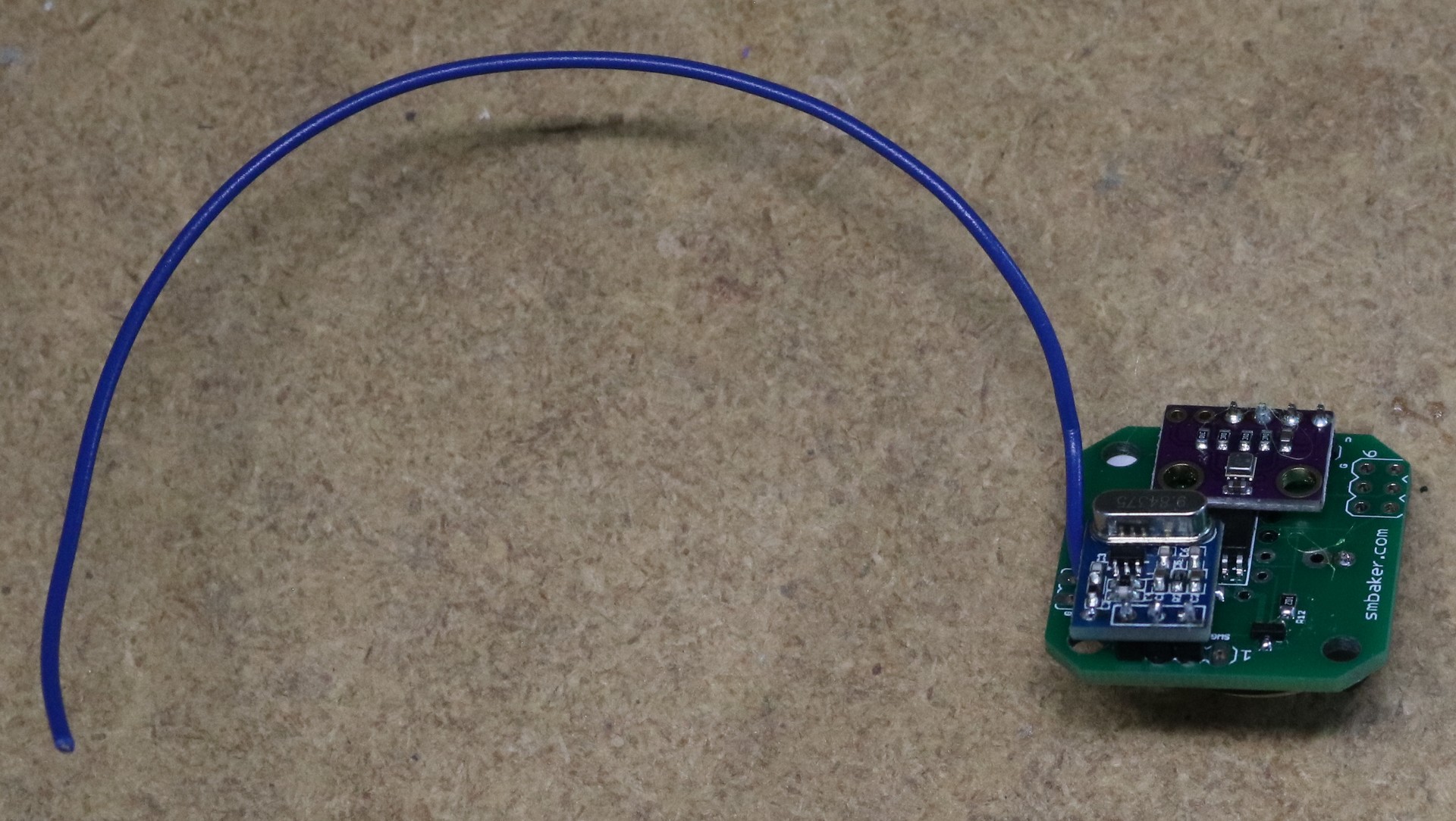
Below is a picture of the board, with and without the breakout boards soldered to it:
The blue wire is the antenna wire. On the underside is a battery holder for a CR2032 battery.
Intermittent transmission requirements
While the 315Mhz band is unlicensed, it’s not without restriction. A device may only transmit for less than a second, and it must not transmit for 30 times the duration that it transmits, with a minimum off period of 10 seconds. This band is also used for devices like garage door openers and remote control switches, so you don’t want to (nor are you allowed to) jam the band with continuous transmissions.
I ended up opting for a transmission time of 250ms or less, and a duration between transmissions of a average of 640 seconds. That’s a transmission approximately once every ten minutes.
Receiving the signal
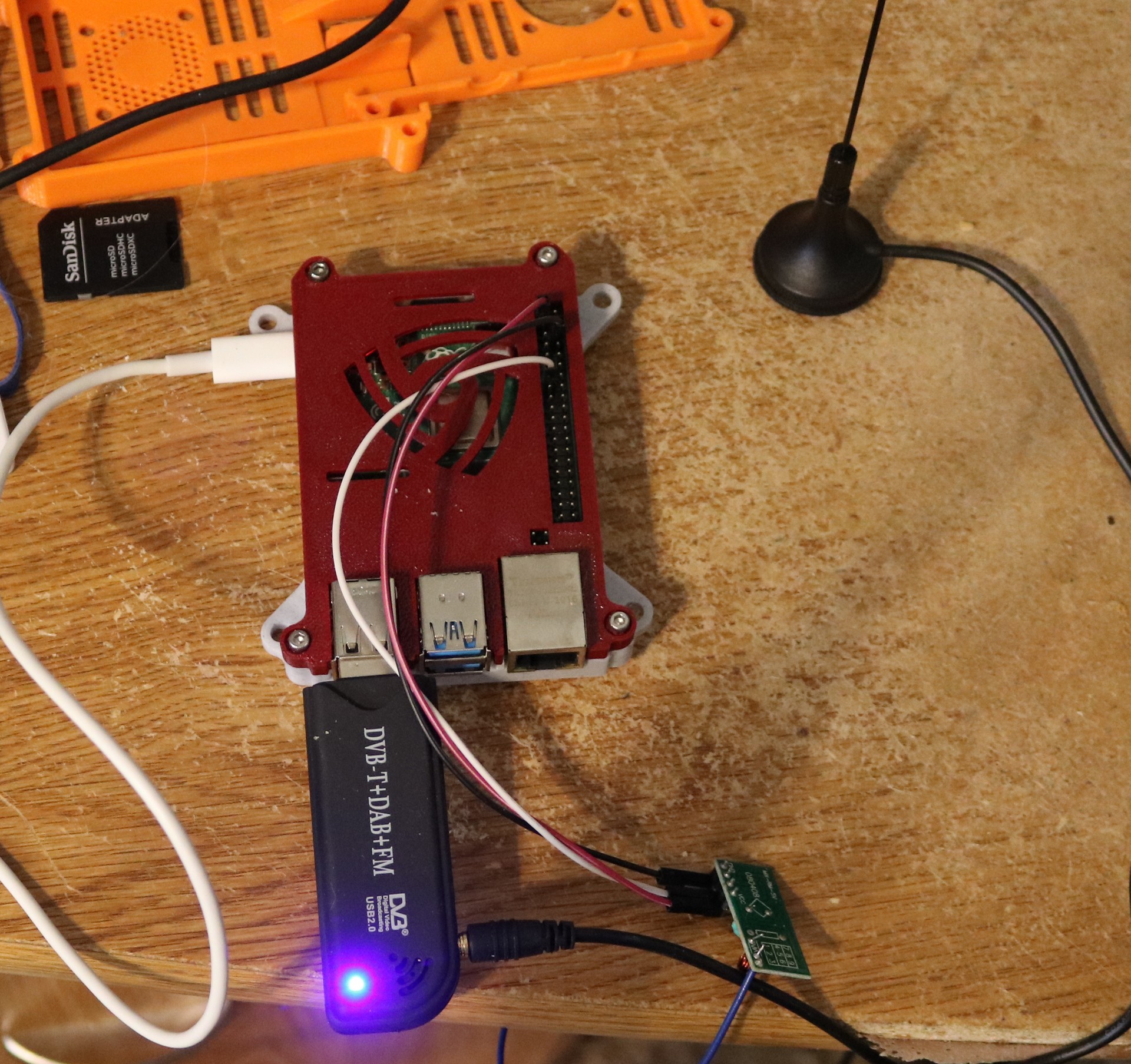
To receive the signals, I use a Raspberry Pi 4 with an RTL-SDR dongle, running a modified version of the rtl_433 software (which despite being called “rtl_433” is capable of also receiving at 315Mhz).
You’ll also see a small receiver board in the above picture — my original attempt was to use the receivers that came with my pack for FS1000A transmitters that I got from Amazon. These cheap receiver boards didn’t work well for me. The RTL-SDR dongle is only about 30 bucks and more than up to the task.
Finally, back to the PrintDry containers…
The sensors allow me to accurately measure the “vacuum” in the containers, which with 10 pumps of the vacuum pumping tool is approximately 100 hPA. 100 hPA is approximately 2700 feet of pressure altitude (i.e. if you walk outside and climbed a hill 2700 feet tall, the difference in air pressure would be about 100 hPA). This is not a “vacuum” in any sense of the word, it’s just 2700 feet of pressure altitude. The moisture isn’t going to boil out of your filament at 2700 feet of pressure altitude. You still need desiccant inside the container in order to control moisture. What the vacuum seal does do, I believe is to ensure good integrity of the sealing surfaces. A traditional rubber seal unless it is very tight may still allow some passage of air across the seal. The PrintDry containers achieve a very tight seal due to the difference in air pressure between the inside and outside. The seal is so good that the plastic clips securing the lid are rather unnecessary — I think you’re not going to easily get that lid open without equalizing the air pressure.
Code availability
The code is available at my github repo at https://github.com/sbelectronics/barometer
I’m encouraged to see that I’m not the only one who’s descended down a ridiculously deep rabbit hole of electronics fabrication on the basis of moisture in 3D printing filament. I haven’t written up most of what I’ve found or worked on, but I do have some interesting (to me) findings here:
https://www.alexwhittemore.com/curious-findings-with-humidity-sensors/
The key takeaway is that, while relative humidity is what drives all the physical processes of moisture transfer, dew point is in lots of ways the more interesting thing to monitor. For instance, in the case of PrintDry “vacuum” boxes – relative humidity is going to go up and down all over the place as ambient temperature changes, but the INTERESTING thing to keep track of is whether dew point changes. If temperature goes up and dew point moves up too, you know you’re pulling moisture out of the filament. Or alternately, you have just found that your underlying assumption about a static airmass has changed, and box air is exchanging with surrounding air.
An experiment that follows from this (that I haven’t properly executed and documented, though have done some proof of concept trial runs of) is to put a ton of (wet) filament in a rubbermaid box with a hair dryer and one of those amazon bang-bang temperature controllers, at, say, 50C (for PLA). Relative humidity will drop with the increasing temperature, but dew point should actually bump up as the heat liberates moisture from the plastic. If you’ve got a little deliberate exchange of chamber air with ambient (as you’d need to actually dry anything), you should see the dew point bump up relative to ambient, then settle back down as all the moisture is vented into the room. Of course, two much exchange and you’ll never see a dew point bump.
Anyway, just a little more fuel for the science fire 🙂
Greetings Dr. Baker,
I really enjoyed your DIY Wireless Temp/Hum/Press remote sensor project. What a great use of easily available parts for a unique monitoring approach. Thank you.
I was curious if you’ve had enough run-time to estimate how long the CR3032 3.3VDC coil cell will last with your design? I am a beekeeper, and would be interested in monitoring/trending the temperature and humidity levels in the hive throughout the year, especially the winter, when cold temperatures and humidity can stress the colony in the hive. The extremely compact nature of your design would lend itself well to hive monitoring efforts.
I was also curious if you will be offering the package as a kit, or at least your custom circuit board for the ATtiny85 baseboard? I’d be interested in acquiring a couple of the sensor/transmitter units, or at least the ATtiny85 circuit boards, to try some experiments with remote monitoring of the temperature and humidity within the bee hive.
Thanks again for your efforts, and keep up the excellent work.
Respectfully,
Ken Sejkora
East Falmouth, MA
I did some back-of-the-envelope calculations and figured them to last a couple years with a CR2032 or a couple months with an LIR2032 (rechargeable but much lower AH than the CR2032). Depends a bit on what your reporting interval is, as there are bursts of large power consumption while the transmitter is running. To run longer, increase the interval. Also, I’m running the CPUs at 8Mhz — could probably get better power efficiency running them at 1Mhz.