In this video, I design an build a PoE-powered lab power supply.
Purpose
What can I say, I like building power supplies. 🙂
Seriously though, I’ve been looking for a reason to play with these DPS5005 and related modules ever since seeing them on popular forums and video blogs. The DPS5005 is relatively well regarded, and has the potential to replace the benchtop lab supply that I regularly use for casual use.
The DPS5005 is a DC-DC converter. It can accept an input voltage from 0 to about 55 volts or so, and will regulate an output voltage up to about 1 volt below the input. This version is good to 5 amps, but there are other versions of this supply that will do as little as 30V / 2A and as much as 50V / 20A. 50V 5A seems like a good sweet spot. Since it is a DC-DC converter, you have to have a DC source to drive it. A lot of people use a 48V power brick, as they are commonly available.
I figured, I’ve already got a 48V PoE switch, in fact I have several of them, I’ll just use one of those. These switches are typical for people using PoE cameras, and recently they have become quite handy for running a raspberry pi using the raspberry pi PoE hat accessory.
PoE Basics
I started out knowing next to nothing about Power-over-Ethernet, then I read a Wikipedia article and now know slightly more than nothing. It’s a start.
Basically, there are two types of PoE: Passive where power is just dumbly injected, and active 802.3af / 802.3at units where the power is negotiated between the switch and the device under power. The active units are of course more desirable as you really don’t want your ethernet energized with 48V to 57V unless the device you’re connecting supports PoE. Disaster could occur otherwise, to the device under power or to the switch. As such this article concerns only active 802.3af / 802.3at PoE.
The Wikipedia article explained the basics of how the negotiation works. There’s two phases: detection and classification. In the detection phase the device places a 24.9K resistor across a couple of the pairs and this signals to the switch that a device wants power. The switch then enters a classification phase where the device negotiates how much power it wants, which can vary from around 5 watts to around 30 watts. Other PoE standards allow even higher power. Anyhow, I’m not going to go into all the details here, just know that it’s neither trivial nor is it overly complicated. A single IC can negotiate it.
Choosing a PoE controller
I went to Digikey and did a parametric search for PoE controllers and settled on the TPS2378. It’s an 8-pin SMD device, capable of automatically handling the detection and classification. It requires a single 24.9K resistor for detection and a specific resistor for classification. Consult the data sheet to learn all about the device, as well as some good diagrams on how the detection and classification protocol works.
The small external component count of the TPS2378 made for a quick design. Normally when implementing a PoE splitter, the next task would be to choose a switching regulator. However, we already have the DPS5005, and it is indeed a regulator, so we’ll feed directly from the PoE controller to the DPS5005.
Design
My schematic is presented below. It’s straight out of the TPS2378 data sheet.
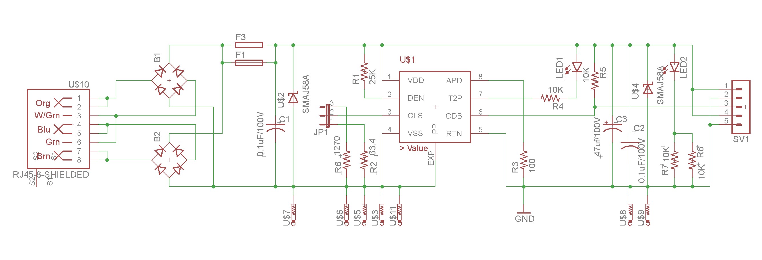
As I said above, the design is straight out of the datasheet. From the left we have the RJ45 jack with it’s four pairs:
- white-orange/orange
- white-green/green
- white-blue/blue
- white-brown/brown
The orange and green pairs feed one bridge rectifier, the blue and brown pairs feed another. The switch can supply power to either set of pairs, or even both at the same time. The bridge rectifiers ensure that polarity is correct, in case someone uses a crossover cable.
Next I have a PTC fuse as insurance against something going horribly wrong. There are two PTC fuses shown in the schematic; they’re just alternate footprints. Then we have a TVS diode to handle transient suppression, and a decoupling capacitor.
Next up is the TPS2378 controller IC. It needs two resistors to configure it. The first, R1, is the 24.9K detection resistor. The other (R2 | R6) is the classification resistor. The datasheet will tell you what value to use for the classification — I chose to go with 1270 ohms (class 0) and 63.4 ohms (class 4), with a jumper to select between them. The auxiliary power detect (APD) pin is an input that I pulled down, and the CDB pin (converter disable) is an open-collector output that I pulled up.
On the output, we have another decoupling capacitor, a bulk capacitor, and another TVS diode just for the hell of it. Finally, we exit on a header.
On my revision 2 of the board, I added some resistors and a LED on the output. It’s important to draw about 0.44 W of power, or the switch will decide there’s no load and turn the device off. A LED is a convenient way to producing a small load. Do keep in mind that the dropping resistor for the LED can get quite hot at 48V so I chose to put two dropping resistors in parallel.
Implementation
I had a custom pcboard fabricated at JLCPCB, like usual.
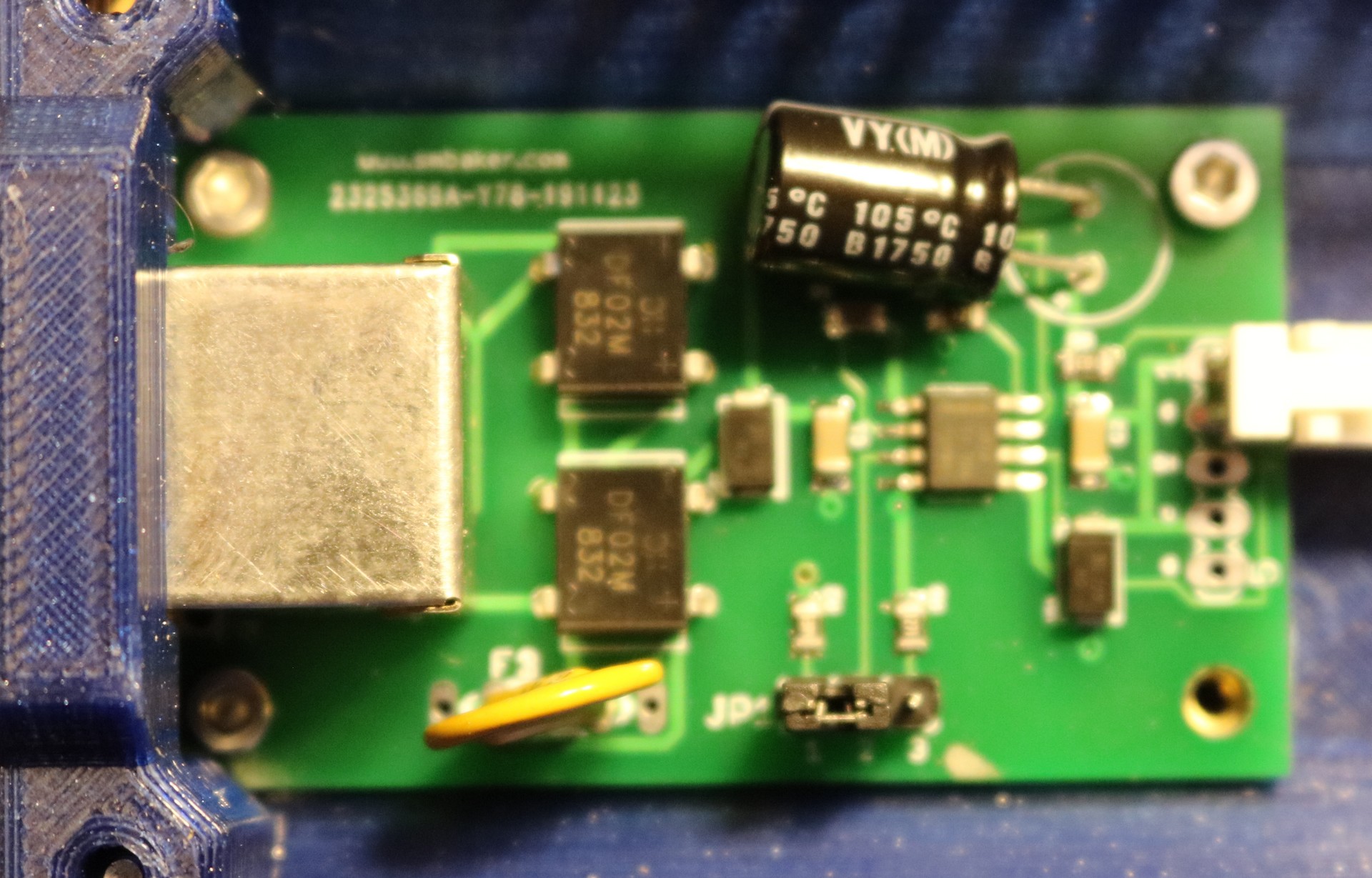
I custom 3D printed a cast and assembled the components inside:
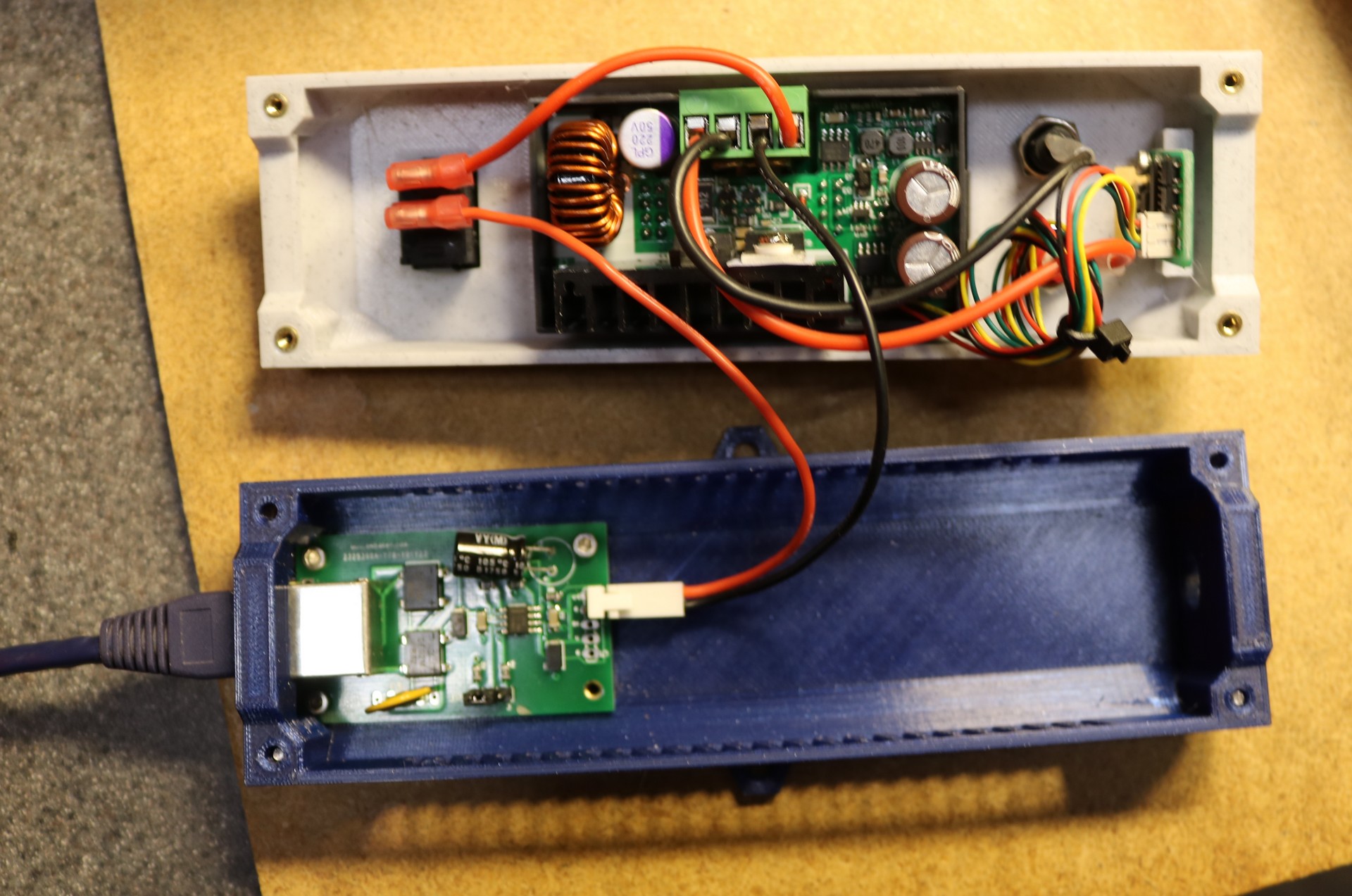
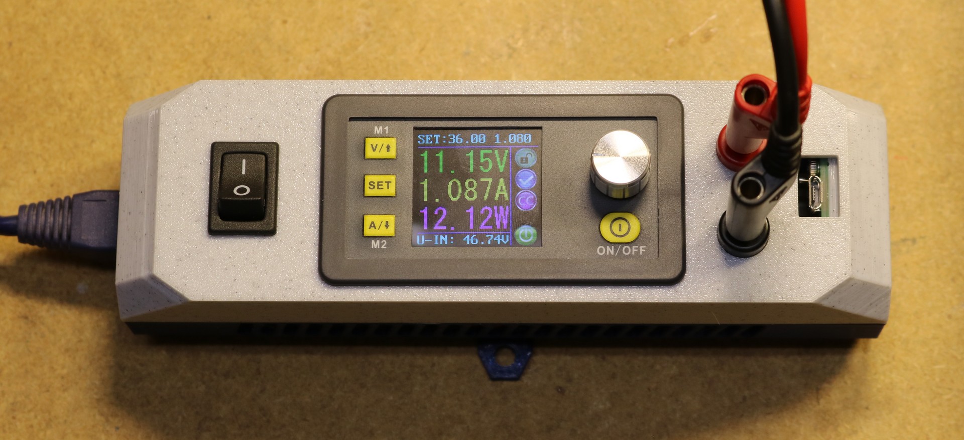
Here is the assembled supply: