I’ve done a few speech synthesizer posts already using the SP0256A-AL2 chip by general instruments. We’re at a relatively fortunate time in that there are some authentic functional chips available on eBay. As always, make sure you do your research and make sure you’re buying from a reputable seller, or at least someone with a decent return policy. Anyhow, I ended up with a good supply of chips, so I thought I’d try to make an ISA speech synthesizer board for my Xi 8088 PC/XT compatible.
Brief intro to the SP0256A-AL2
The SP0256A-AL2 is a phonetic speech synthesizer. It breaks speech down into 64 different phonemes (including some pauses) that allow you to effectively create arbitrary english speech. It does not in and of itself offer text-to-speech capability. You are responsible for the logic that converts text into phonemes. For example, to say my name (Scott), one has to send the phonemes “SS KK2 AO PA3 TT1”. The IC has a parallel interface with 8 data bits and a “LRQ” (Load Request) pin that tells the IC to load the phonemes that are on the data bus. There are two status pins, ALD and SBY. ALD will go active when the IC is ready for a new phoneme to be loaded. SBY will go active when the IC is busy.
Design
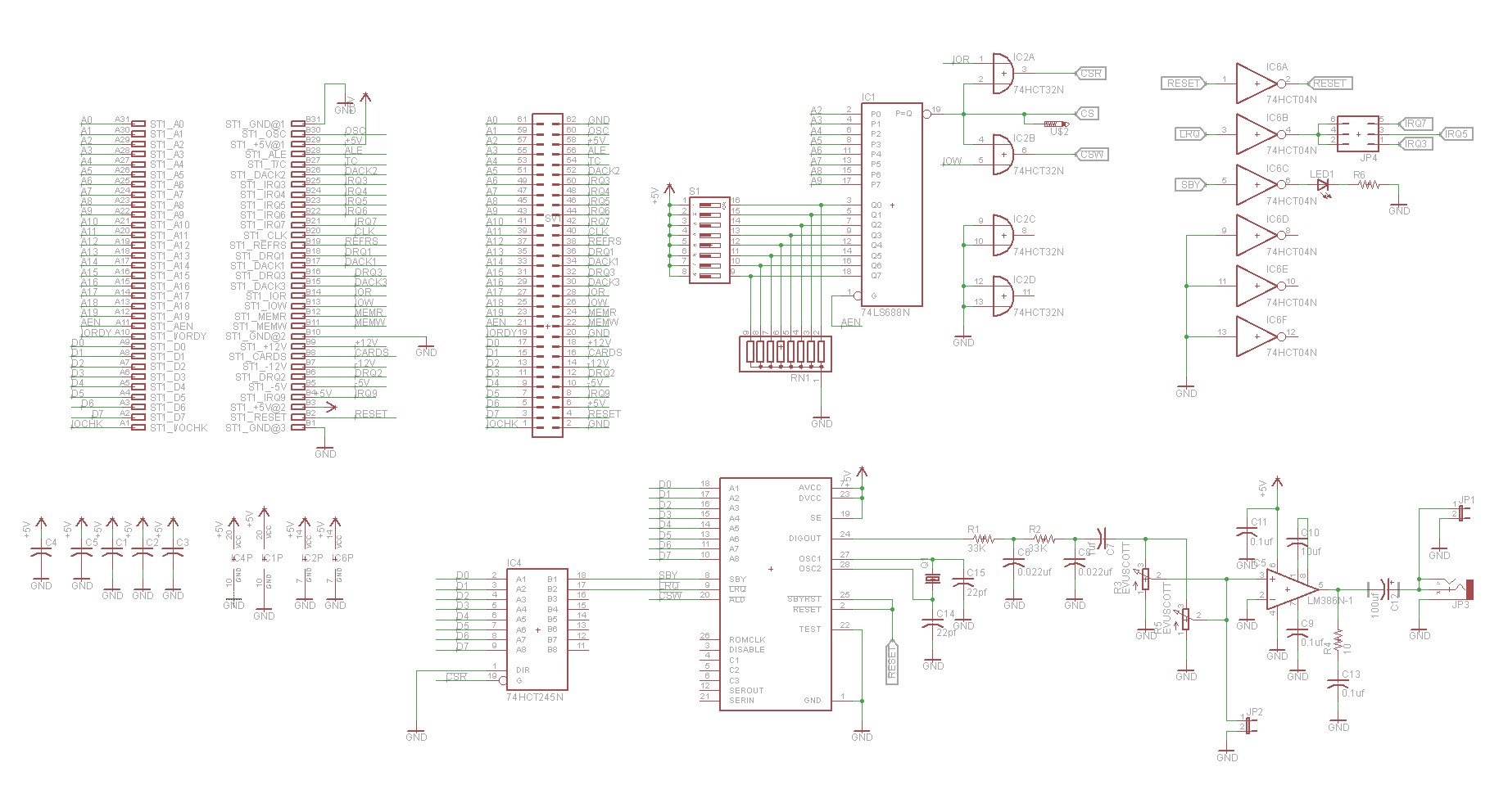
Here is the schematic that I came up with:
The upper left corner is the 62-pin ISA bus. Typically on my ISA cards I use both the typical ISA edge card connector as well as a dual-row header. The header makes it easy to attach debugging leads if necessary, or to hack things up in the case of a mistake.
Upper middle has the address decoding section. I used a 74HCT680 identity comparator. What the 680 does is to compare two sets of data lines (P and Q). If all of the P bits are equal to all of the Q bits, then it will assert its output. This makes it perfect for using a dip switch to select addressing. The ISA bus allows 10 bits of addressing, but the 680 only supports 8 bits, so I chose to use the upper 8 bits. Thus the speech synthesizer will occupy four consecutive port addresses. I tend to put it at address 0x120, so it ends up occupying 0x120 – 0x123. Once the address is selected, we need to do a little more work to get our read and write strobes. This is done with a 74HCT32 OR gate. We OR the address select together with the ISA BUS’s RD signal to get a CSR (chip-select-read) and we OR the address select with WR to get a CSW (chip-select-write). The CSW signal we can feed directly into the SP0256A-AL2’s LRQ pin.
Upper right has some hex inverters. The primary need for this is the RESET signal. The ISA BUS reset line is active high, whereas the SP0256’s is active low. So we just need to invert it. I also brought out a header in case we’d like to try connecting to speech synthesizer to an interrupt, so we could try an interrupt-driven approach instead of polling. Finally, another inverter is used to drive a LED that will light whenever the speech synthesizer is talking. Maybe the LED would be handy if you’re experiencing an audio-output issue, but really it’s just there for added sparkle.
The bottom half of the schematic is dominated by the SP0256A-AL2. To the left of the SP0256A-AL2, we have a 74HCT245 that I use to allow us to poll the SBY and LRQ signals. It’s selected by the CSR signal that came out of the address decoding. Basically, if we write the speech synthesizer port, we’ll cause a phoneme to be spoken. If we read the port, then we’ll poll the two status lines. To the right of the SP0256A-AL2 is the audio amplifier — it’s straight out of the Radio Shack datasheet.
Implementation
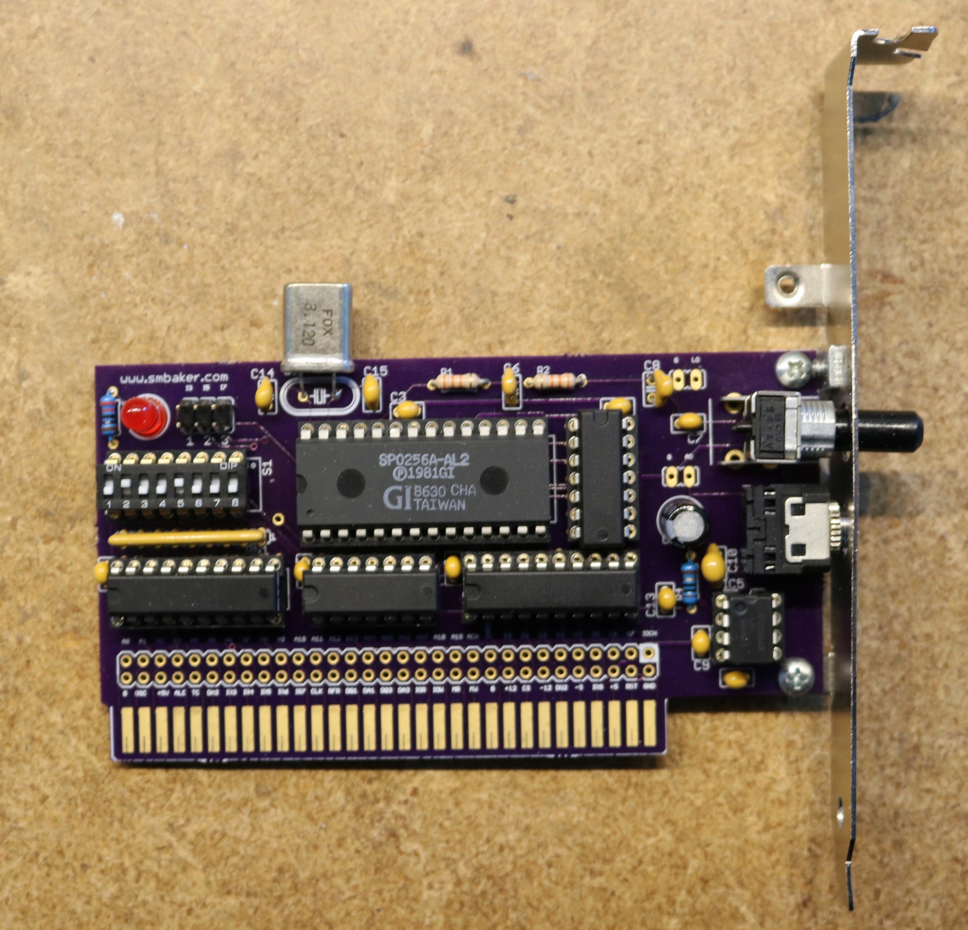
As usual, I used Osh Park to fabricate the PC Board. Here is the board after all components have been soldered:
The only thing that’s really noteworthy about the PC-Board is that I didn’t make it quite tall enough to mount the keystone bracket, and I had to use a small 4-40 right angle bracket from Sparkfun to securely attach the keystone bracket to the card. The pot is also a little on the tall side and just barely misses the slot cutout in a typical PC case. Next time I’ll probably try to make the PC-Board card a little taller so the bracket is more straightforward to attach (generally, I make PCBs as small as possible, to save on money).
The dip switches as shown are set to address 0x120 (keep in mind, these are the upper 8 bits of the 10-bit port address).
Software
I wrote a driver for the speech synthesizer board, in Turbo Pascal. The driver is available at https://github.com/sbelectronics/pctalker. It has a few different ways that you can use it. If you use the -D option, then it will speak the phonemes directly. For example,
say -D SS KK2 AO TT1
If you use the -L and -B options, then it will install itself as a TSR and attach itself to lpt3. This allows you to use DOS commands like ECHO or TYPE to send output to the speech synthesizer at any time, and it will talk in the background. For example,
say -L -B
echo “SS KK2 AO TT1” > lpt3
Board Availability
As usual, the PCB is up on Osh Park:


Uhh. Shouldn’t it be an AND gate? ORing the address select line and the ISA IO read/write lines doesn’t make any sense…
The address select and the read/write lines are all active low, so you want an OR gate:
Hey, thanks for taking the time to post this and creating the PCB – having created PCB’s myself, I know how much time it must have taken.
Awesome! Thank you! The speech synthesizer chip is so expensive on eBay, unfortunately.
Good job. Have you try this program which run in DOS?
https://github.com/charlierobson/chiptalk-syb/blob/master/tx2al/tx2al.c