In this video, I measure the voltage drop on USB Power Cables using a Power Supply, DC Load, and Multimeter:
Motivation
When I did my Seeed Studio Fusion PCB Review, I ordered a new board for my Raspberry Pi Midi Jukebox, that featured a 3.5×1.35 barrel jack for power. I like barrel jacks instead of micro-usb, as it’s easier and more foolproof to plug in a barrel jack. Anyhow, it didn’t work. The pi just sat there and blinked. No ssh. No VFD display. Did I design a bum PCB? Did I short something out when I plugged it in? Did I somehow ruin my pi?
It turned out to be one of those things you might not think of — the power cable. The project worked fine with the USB-MicroUSB cable that I normally use with my pi. However, it didn’t work with the USB-3.5×1.35 cable that I bought from ebay. Once I realized the power cable was the culprit, it immediately seemed likely that it was a voltage drop issue due to small wire or some other manufacturing issue. I set out to measure several cables and compare the results.
DC Load Design
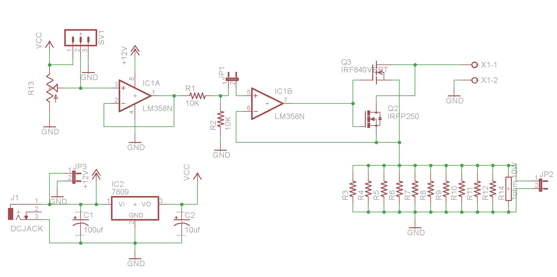
The DC Load was based on Dave Jones’s EEVBlog episode 102. My schematic pretty much follows Dave’s design. Here is my schematic:
The terminal block X1-1 / X1-2 connects to the binding posts. The positive voltage from the binding post passes through a mosfet (Q2 or Q3, populate one or the other but not both) and then through a current sense resistor (R3-R14). The current sense resistor can either be a single big resistor or a lot of small resistors in parallel depending on what components are on hand. An opamp, IC1B, is used to control the mosfet, using the sensed current and a multi-turn pot as inputs. The current sense resistor is chosen to be 1 ohm, so that 1 volt across this resistor will equal 1 amp of current.
I’m not going into much detail on how this works — the EEVBlog video does a much better job than I possibly could.
DC Load Implementation
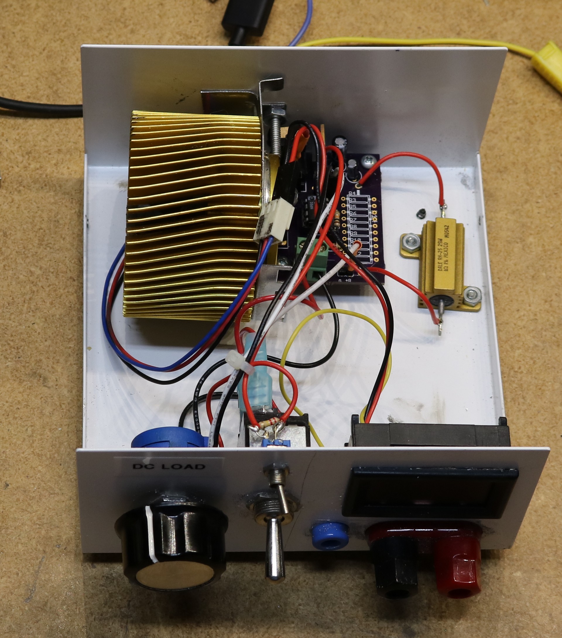
The DC Load was built pretty much from spare parts, eBay finds, and a custom OSH Park pcboard.
Several things to note in this picture:
- The large heat sink is some old pentium CPU cooler. I drilled and tapped it, and mounted the power mosfet (IRFP250) to it.
- The small gold component on the right is a precision 1 ohm resistor that I bought on eBay.
- The pot is a multi-turn (probably 10-turn) from eBay.
- The DC panel meter, also from eBay, displays the milliamps that the load is sinking.
Test Methodology
My test setup used three pieces of equipment:
- Benchtop power supply, set to provide ~ 5V at up to 3 amps.
- DC Load, capable of creating a load from 3ma to several amps.
- Fluke multimeter, to measure the voltage at the load.
For each cable, I set a fixed output at the power supply, and then varied the load from 3 milliamps (the lowest my DC load is able to create) up to about 2 amps. At each different load value, I wrote down the voltage observed at the load.
The Cables
Here are the cables that I tested:
- bar35: USB to 3.5×1.35mm barrel jack. This is the cable that failed to power my project.
- bar55: USB to 5.5mm barrel jack.
- bar55_sw: The bar55 cable with an inline power switch attached.
- bar55_adapt: The bar55 cable with a 5.5mm to 3.5×1.35 adapter attached.
- musb_long: USB to micro-USB cable, somewhat long and thick.
- musb_retract: Rectractable USB to micro-USB cable, marked “PLX”, probably from a kickstarter.
- musb_short: A relatively short and thin micro-USB cable.
Results
Below is a chart that records the observed voltage at each milliamp setting on the DC Load. For example, the bar35 cable resulted in a measured voltage of 3.17 volts at a load setting of 300 milliamps.
| milliamps | bar_35 | bar55 | bar55_sw | bar55_adapt | musb_long | musb_retract | musb_short |
| 50 | 4.73 | 5.03 | 4.99 | 5.03 | 5.04 | 4.98 | 5.05 |
| 100 | 4.41 | 5 | 4.9 | 4.99 | 5.01 | 4.9 | 5.02 |
| 150 | 4.11 | 4.96 | 4.83 | 4.95 | 4.98 | 4.8 | 5.01 |
| 200 | 3.8 | 4.93 | 4.75 | 4.91 | 4.95 | 4.85 | 4.98 |
| 250 | 3.49 | 4.89 | 4.67 | 4.88 | 4.93 | 4.79 | 4.96 |
| 300 | 3.17 | 4.86 | 4.59 | 4.84 | 4.91 | 4.83 | 4.92 |
| 350 | 2.86 | 4.82 | 4.51 | 4.81 | 4.86 | 4.78 | 4.9 |
| 400 | 2.54 | 4.79 | 4.43 | 4.78 | 4.82 | 4.74 | 4.89 |
| 450 | 2.21 | 4.75 | 4.36 | 4.75 | 4.82 | 4.71 | 4.84 |
| 500 | 1.87 | 4.72 | 4.28 | 4.7 | 4.79 | 4.69 | 4.86 |
| 750 | 4.54 | 3.88 | 4.52 | 4.66 | 4.53 | 4.75 | |
| 1000 | 4.38 | 3.48 | 4.34 | 4.54 | 4.3 | 4.68 | |
| 1250 | 4.2 | 3.11 | 4.17 | 4.39 | 4.16 | 4.6 | |
| 1500 | 4.04 | 2.74 | 4 | 4.29 | 4.06 | 4.52 | |
| 1750 | 3.87 | 2.39 | 3.81 | 4.18 | 3.84 | 4.42 | |
| 2000 | 3.7 | 3.6 | 4.05 | 3.69 | 4.38 |
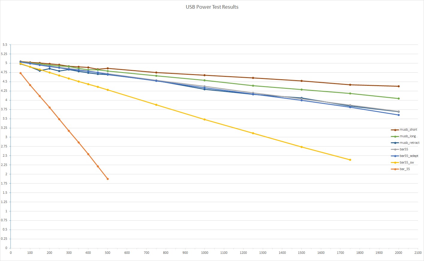
The same data, plotted in a graph:
Some interesting observations from these results:
- The USB-to-3.5×1.35 cable that failed to power my project performed the worst. The closest I was able to measure was 1.87 volts at 500 milliamps. My project expected something close to 5V at 600 milliamps. It’s not surprising it failed.
- The USB-to-5.5mm cable did pretty well, but its performance suffered dramatically when I added the inline switch. Must be something funky with that switch.


I stopped fighting with lousy pre-made USB power cables for use with the likes of the Raspberry Pi. Instead I make my own beefy cables with minimal I*R losses.
This is a far from and ideal solution however. Remember: Do NOT increase the 5V supply voltage to compensate for cable drop loss, especially if your near-end cable voltage exceeds the maximum allowable input voltage of the load device! If your load varies (as it will with the likes of a Raspberry Pi), you risk feeding too much voltage to the load when it draws less power.
A much better solution is to build your own USB power supply with “Cable Drop Compensation” (a.k.a. four-wire or Kelvin type far-end sense feedback). Let’s say you have a switching buck regulator (a linear regulator will work too, but watch out for heat dissipation): Use two large gauge (low I*R drop) wires for the power delivery and two small gauge wires across the far-end of the cable to send the feedback voltage to the sense input of the regulator. Now the cable drop is included in the regulation loop and you will always have 5V at the far-end of the cable.
If you use a buck/boost regulator (other types will work, e.g. some SEPIC regulator topologies), you can feed the regulator input with 5V and get always get 5V at the cable far end even with cable drop present, PROVIDED the cable is in the regulator feedback loop.
Of-course with Cable Drop Compensation design, the Devil is in the details, especially with switching regulators. Consider cable parasitic inductance and capacitance effects, especially if you introduce the likes of Ferrites in the cable power-path to reduce EMI.
Also keep in-mind that regulation depends on having a relatively high-impedance sense feedback input, which may require the introduction of a buffer. Keep an eye on feedback signal integrity and conditioning too. Keep the feedback path clean, but take into consideration transient bandwidth (don’t over/undershoot during transient loads and especially during input power turn-on!). And finally there’s the always the chance of introducing instability by extending the feedback sense feedback path. If-possible first SIMULATE then VERIFY with test loads under different transient conditions before applying any solution to a production load.
Linear Technologies (now owned by Analog Devices Inc.) has some nice switch-mode regulators for USB that have Cable Drop Compensation built-in. Plus you can simulate designs with some of these LT parts with LT’s free LTSpice simulator (runs native in Windows, but works OK in Linux under Wine).
Look at this LT page first:
http://www.linear.com/parametric/Cable_Drop_Compensation
At first-glance take a look at this part (can be simulated in LTSpice):
LT8697 – USB 5V 2.5A Output, 42V Input Synchronous Buck with Cable Drop Compensation
http://www.linear.com/product/LT8697
Have Fun! David
Disclaimer: I have no affiliation with Liner Technologies or Analog Devices, other than as a Customer.