In this post, I design and build a LED clock for my daughter:
Motivation
I had been using a Nixie Tube clock in the baby’s room. As the baby grew older, she not only became mobile, but has also picked up a new hobby, smashing things. As such, the nixie clock had to be replaced with something less dangerous. I had some 1″ 7-segment LED displays from a previous project, so I decided to modify the clock design to function around those.
Design
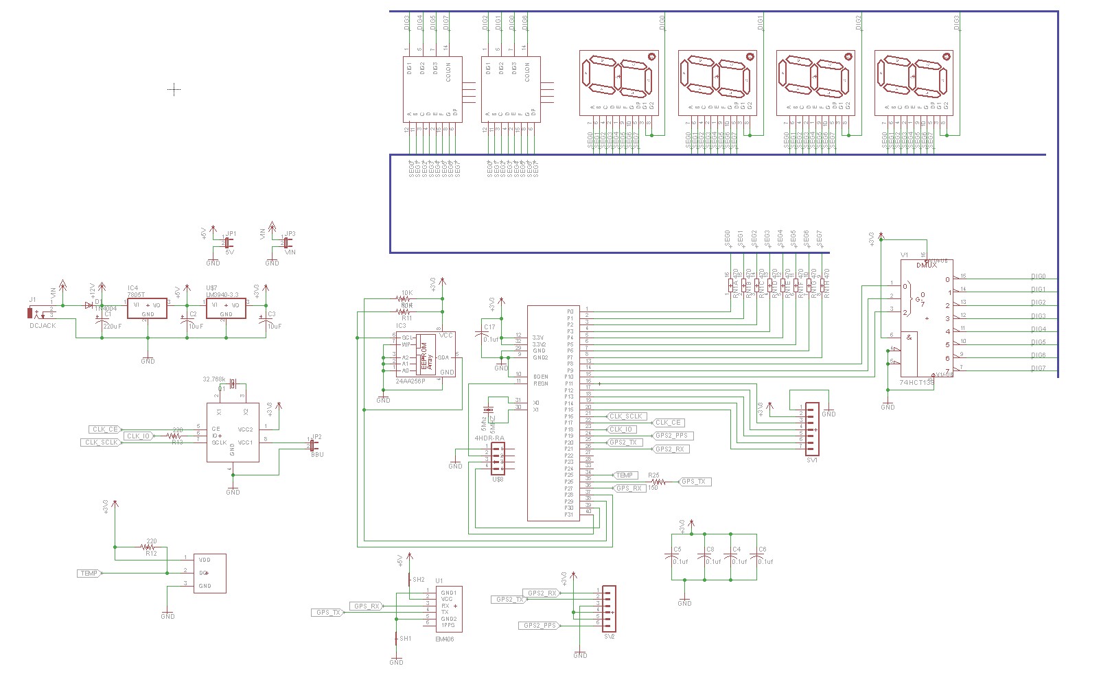
The schematic is shown below:
The CPU used is a Parallax Propeller. The propeller doesn’t have onboard program memory, so there is a separate EEPROM that contains the program. There are three different ways to keep time: 1) a Dallas DS1302 realtime clock, 2) A UP-501 GPS Module, or 3) An EM-406 GPS module. You only need one of these. At the time I designed my Nixie Tube clock, I was fond of the UP-501, and had one left on hand so I used it here. Unfortunately to great regret, the UP-501 is no longer manufactured. My research shows that a PAM-7Q might be compatible, and I might try to get some of those on hand to power future clock projects.
The displays are multiplexed. There are two different display options:
- Individual 1″ digit 7-segment LED displays. These ones I obtained from eBay. Due to the large size, only four of these fit in the clock, so we only get hours and minutes displayed. If choosing these, it’s important to get displays with a forward voltage of 3 volts or less. Note that some 1″ displays found on eBay contain two LEDs in series per segment, and for example this could result in a 3.6V forward voltage.
- 0.4″ 3-digit 7-segment displays. These are digikey part number 160-1545-5-ND. These are relatively small. The clock is designed to support two of them, for a total of 6 digits, allowing seconds to be displayed.
Choose either of the two 7-segment LED options, not both.
There’s also a pad on the board for a dallas 1822 thermometer. The idea there was to support repurposing this board as a thermometer if I chose to do so.
There’s a DIP resistor that’s used to set the current for the LED displays. For 1″ blue 7-segment displays with a 3V forward voltage, I found no resistor was necessary and just shunted them across. The common cathodes of the displays are driven by a 74HCT138 3-8 decoder.
Implementation
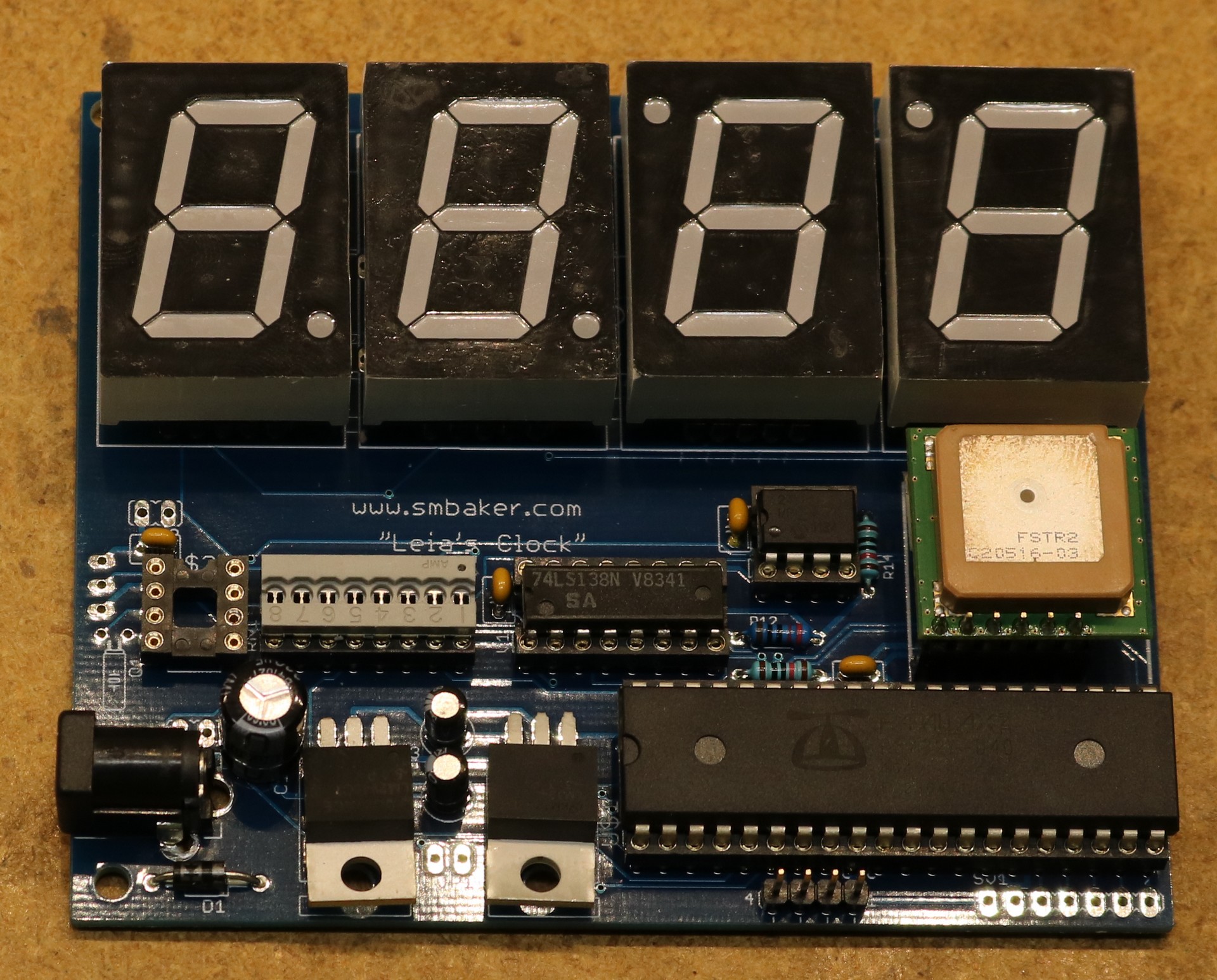
These boards were fabricated using Seeed Studio Fusion PCB, as I had room to toss them onto another order. Here is a picture of a completed clock board:
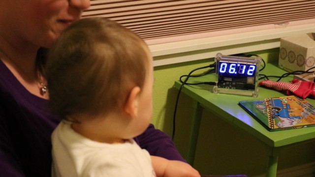
Here is a picture of the completed clock on Leia’s table:
Software
The software is up in my github repo, same place as the original nixie tube clock: https://github.com/sbelectronics/prop-nixieclock


