A couple of videos where I take a ~ 1950s Seeburg 3WA wallbox and convert it into a media player for my homebuilt audio player:
Motivation
I saw a blog post where someone else converted a Seeburg wallbox, and it set me on my own journey.
A bit of background. These Wallboxes were used as remotes in diners and other locations back in the 1950s. You put your nickel, dime, or quarter into the Wallbox, which racks up some credits. Then you select the song you want and the Wallbox sends a signal to the Jukebox, which adds your selection to the queue. Soon thereafter your music is playing through the diner. I’m too young to have experienced these in person when they were state of the art, but I do have an appreciation for antique and retro projects.
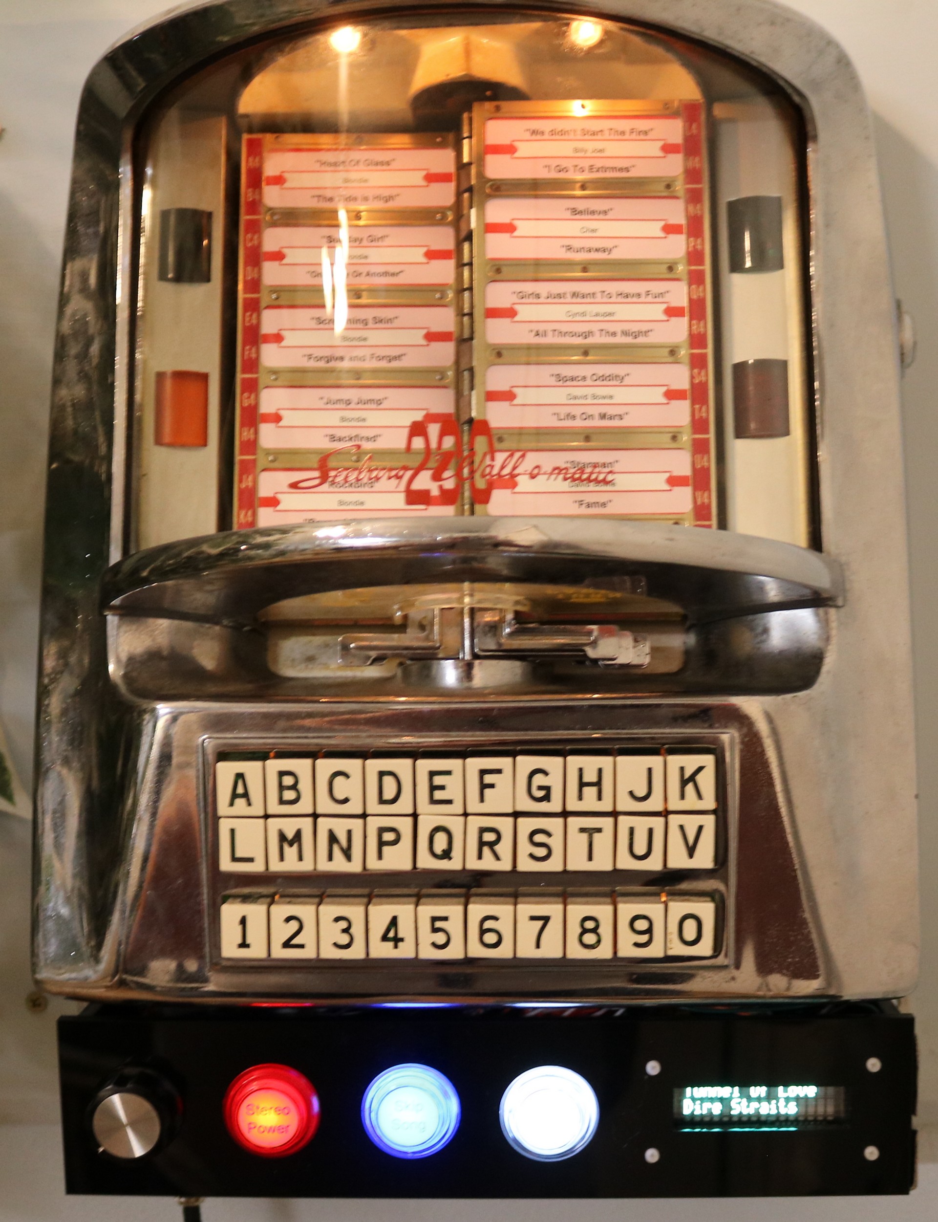
A new fad is to convert these wallboxes into remotes for your home audio system, be it Sonos or something else. I have my own homebuilt audio system, basically an augmented Pandora player, so my goal was to use the wallbox to control that. Here’s what I ended up with:
Wallboxes 101
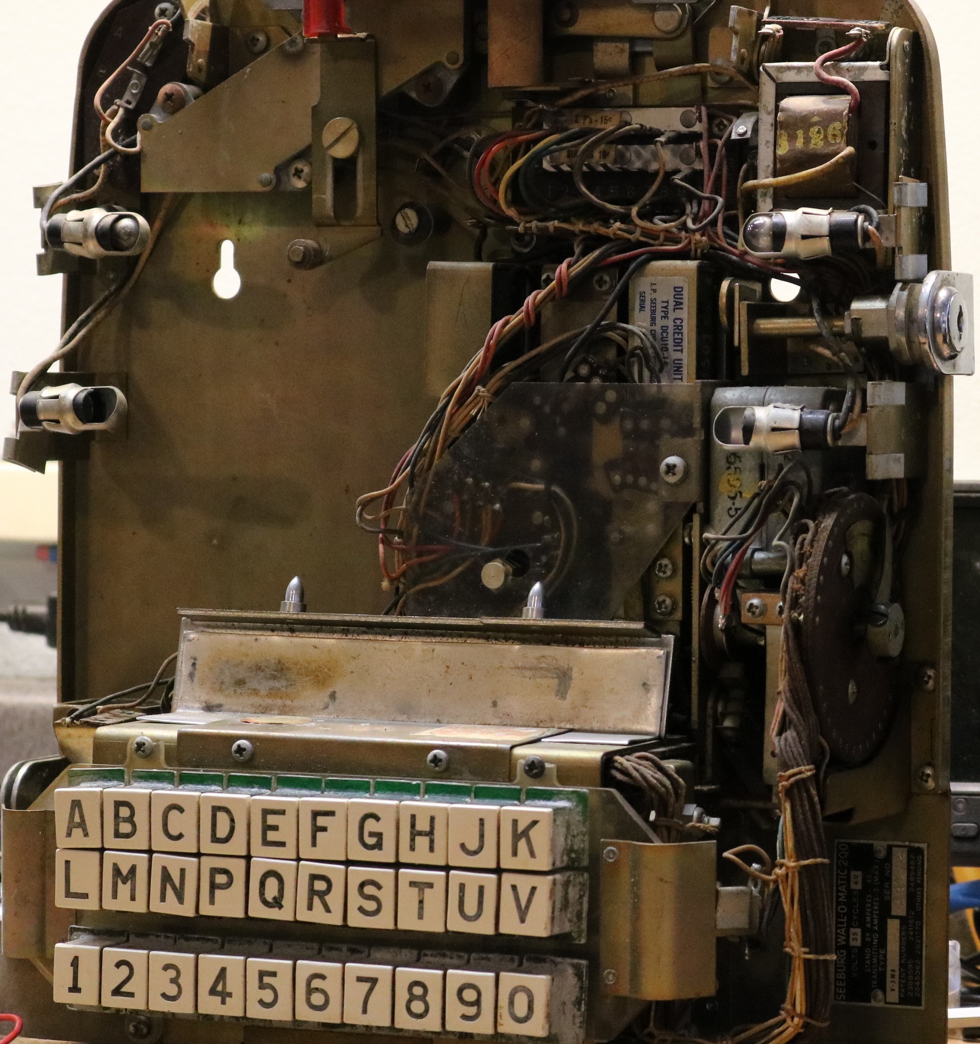
Many of these wallboxes run on 25 VAC, so you’ll need to get your hands on an appropriate AC transformer in order to power up the wallbox. The thing is full of old inefficient incandescent bulbs, solenoids, motors, gears, cams, and leaf switches. Here’s a picture of the innards:
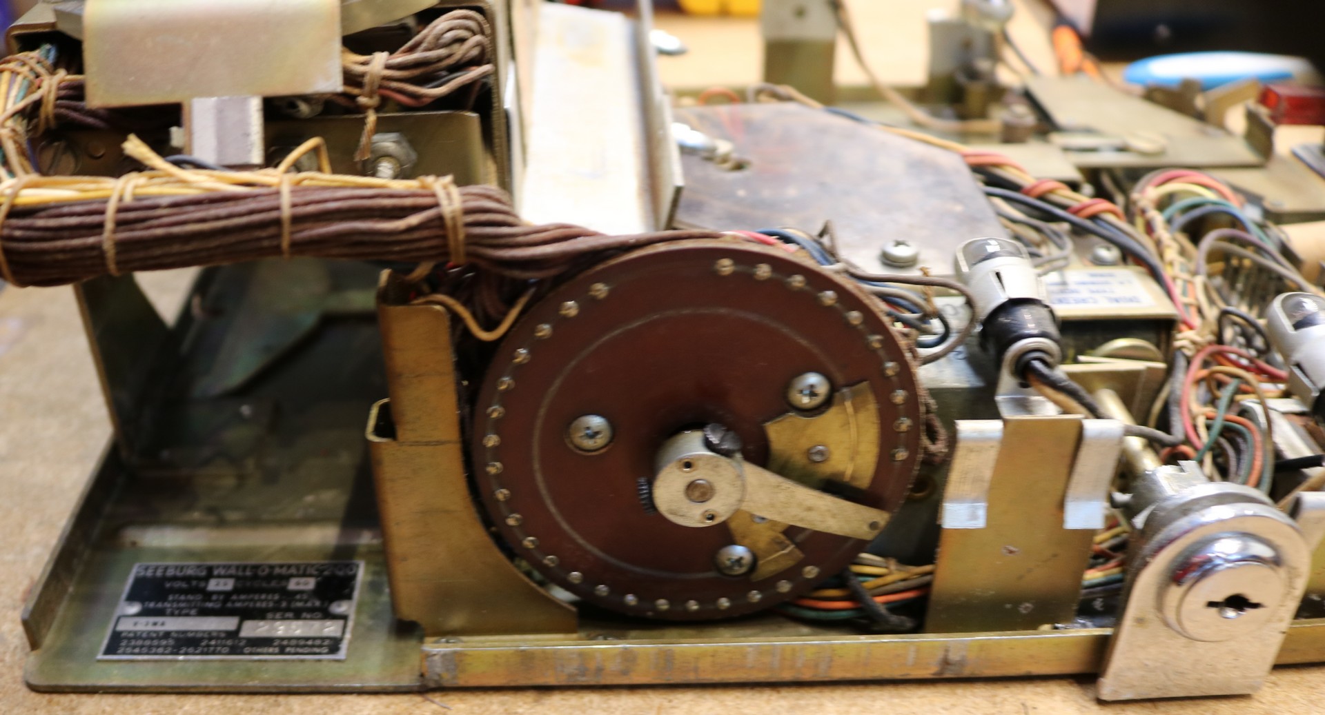
The function of the keys should be fairly obvious — you select a letter (for example, “A”) and a number (for example, “1”) and that specifies the song you want played on the jukebox. What isn’t obvious is how exactly that signal is encoded. These days we would use an IO Expander or a Shift Register, or similar logic to convert the parallel data (buttons) into serial data that we could send to our music player. Back in the 1950s, they didn’t have IO expander ICs or shift register ICs, but they still made do. They way they did it is with a motor!
The encoder disc has a movable arm connected to a motor. On the disc are many little contacts, which connect to the various buttons. If you press a button, it will break the circuit at some point as the motor spins the arm around the disc. For example if you push “A 1” you’ll get two pulses for the “A”, followed by one pulse for the “1”. If you press “V 7” then you would get 21 pulses for the “V” followed by 7 pulses for the “7”. It’s an electromechanical shift encoder.
Decoding a train of pulses on a raspberry pi isn’t hard, we just count the number of pulses for the letter and digit, and then we have a song list that tells what song we want to play. Of course, there’s going to be a little more to it than that — this thing is a noisy old 25 VAC appliance, emitting yucky AC pulses from a moving arm over grungy old contacts. It’s not the cleanest thing in the world to try to decode. I’ll cover signal conditioning later.
The other interesting thing about the 3WA is the “dual credit unit” or DCU. The DCU is responsible for counting the number of credits you have accumulated based on the coins you insert. A quarter gives you 6 credits, a dime 2, and a nickel 1. Some songs cost 3 credits, other songs cost 2. So putting in one quarter will let you play two 3-credit songs. The DCU is another fantastic contraption of solenoids and wheels and contacts, and not something I’m going to dive into, as I sure as heck don’t want to take apart a DCU and try to get it back working again. My DCU mostly works — that’s good enough for me.
Selecting your Wallbox
One source of Wallboxes is eBay. There are many other brands besides Seeburg, but I personally like the appearance of the Seeburg wallboxes. The two common models are the Seeburg 3W1 and the Seeburg 3WA. The 3W1 is a 100-selection wallbox and has one row of letters and one row of numbers. The 3WA is either a 160 or a 200 selection wallbox and has two rows of letters and one row of numbers. The only difference between the 160 and 200 versions is a removable stop that prevents a couple of the song catalog pages from turning. The 3W1 is considered by some to be the simpler of the two due to the lack of the dreaded DCU.
eBay is one source, but not the only source. There are a few vendors on the web, you can find ’em by googling “seeburg wallbox” easy enough. Personally, I bought mine through eBay from what seemed like a reputable dealer who did a decent job of describing the unit and seemed to know what he was talking about. Beware that these wallboxes are old, and like all old things, they may have various problems. Unless it’s explicitly stated that everything is working, expect that you might need to spend some time diagnosing issues like dirty contacts, misaligned cogs, or bent leaf switches. There is a manual on the web, and the manual will be a lot of help.
One thing to pay attention to when buying your Wallbox is whether or not it comes with the key. These things were full of coins while sitting in the diner, and of course had to be locked, if the owner wants to make sure his coins don’t walk away. Keys often get lost, which is understandable given that a diner could have a dozen or more wallboxes and only a few sets of keys. Sometimes you can find the key number imprinted on the locking mechanism and you’ll know what key to order. If it’s not printed, then you might have to order a whole new lock and key. Obviously, ordering just a key is cheaper than ordering a lock and key. So pay attention to this when picking your wallbox.
Initial Maintenance
You’ll want to pop out the song catalog page assembly as you’re probably going to be printing up your own custom song listing. There are templates for printing the title strips at cdadapter.com. I recommend using heavy card stock. Before printing and inserting new title strips, make sure to clean the song catalog assembly, as it’s probably all grimy. There’s supposed to be a spring that holds it open to “page 1”, but many of these have broken springs. You can buy new springs online.
Expect that you’ll have some burned out bulbs. The big bulbs are #55. The small bulbs are #51. You can find them at Amazon. Personally, the replacements seem a little dim to me.
Problems that I had with mine included: 1) the rotating arm on the selector wheel being misaligned, 2) a leaf switch slightly bent, 3) dirty contacts on another leaf switch. The Seeburg manual will guide you through many of the things to look for.
Assembling a Power Supply
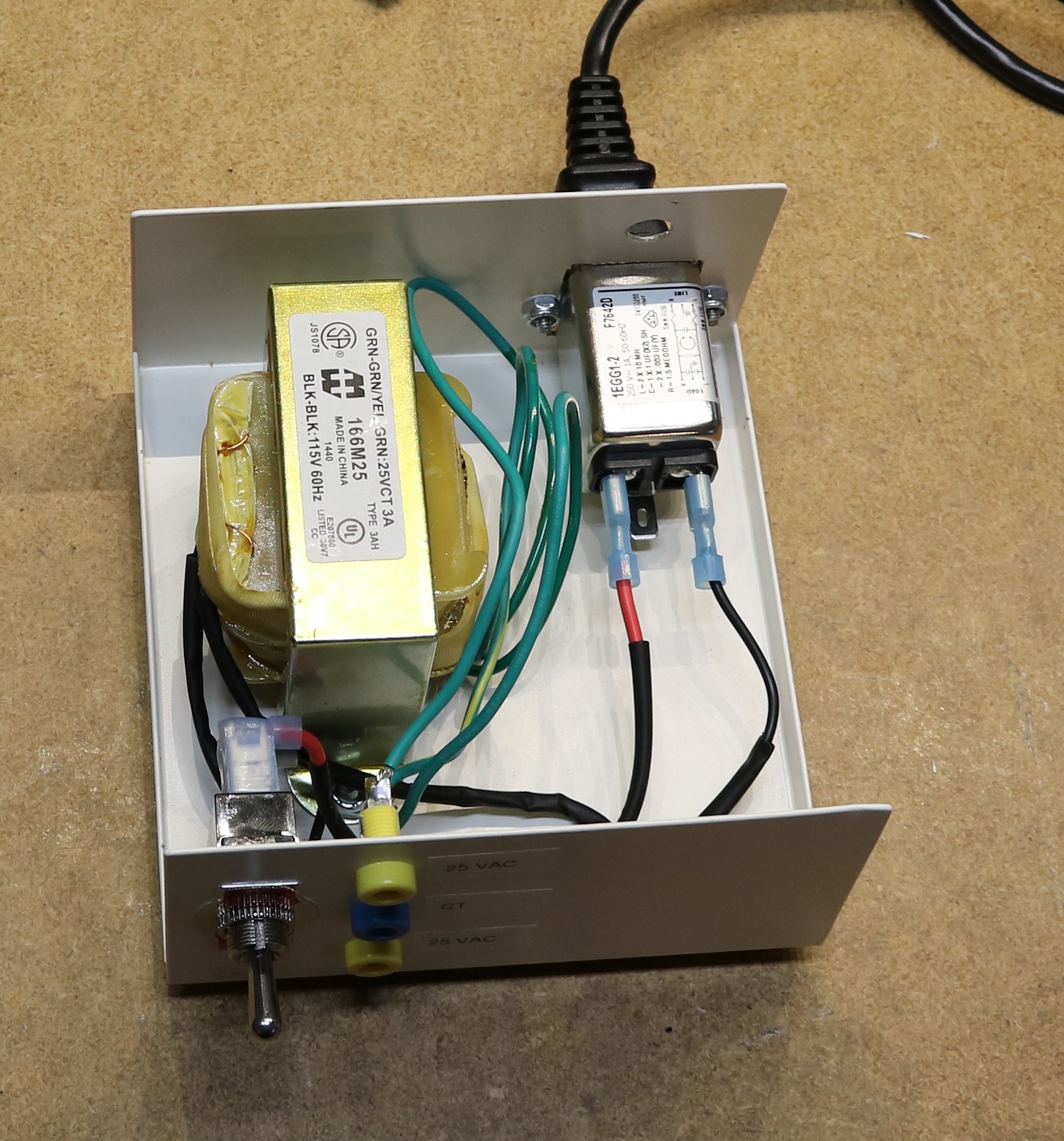
One of the first things you’re going to need to do is to put together a power supply. Fortunately, this is relatively simple. The Seeburg uses 25 VAC, and a recommended transformer is the Hammond 166M25, part number HM556-ND at digikey. 3 Amps should be sufficient. You’re also going to want a fuse, a power switch, and some means to connect the power supply to AC mains. I used a corcom power-line entry filter, part number 1EGG1-2, digikey part number 1EGG1-2-ND. The nice thing about using a power entry filter is that they typically combine an AC receptacle for a computer power cable, a filter, and a fuse holder all in one. Below is a picture of my assembled power supply:
As you can see, I used some banana jacks on the front. That’s great for connecting test leads, but not necessarily the most convenient for permanent installation. I ended up installing a GX14-4 “aviation connector”. It’s kinda like a DIN-connector, and mounts nicely on an enclosure. You can find Male and Female sets of these plugs on eBay. You technically only need the two 25 VAC wires from the transformer, though I also plumbed through the center-tap to the banana jack and aviation plug, because you never know when you’ll want to cannibalize this transformer for some other purpose.
The fuse is important. I shorted something and blew fuses twice while diagnosing the wallbox. Technically it might make sense to fuse the 25 VAC output of the transformer in addition to the mains input, but for me the mains input fuse in the Corcom filter worked just fine and kept anything from getting destroyed.
Connecting your Wallbox
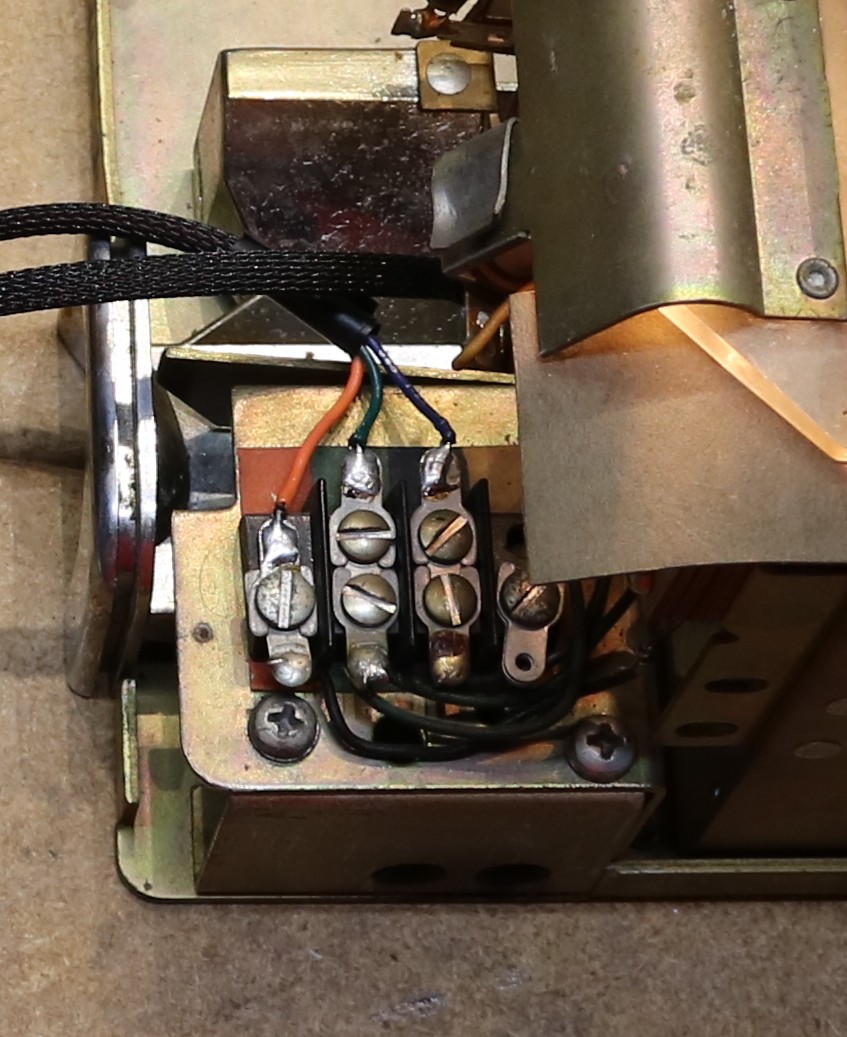
The Seeburg 3WA has a three-terminal block:
From left-to-right we have:
- Orange: 25 VAC. This one is marked with a ground symbol in the schematic. Connect this to one end of the secondary winding in your 25 VAC transformer.
- Green: 25 VAC. Connect this to the other side of the secondary winding in your 25 VAC transformer.
- Blue: Output. This is the output of the selector disc and tells the jukebox which song to play. As the arm on the disc spins around, it’ll be shorted to Orange depending on which buttons are pushed for various contacts on the disc. To see the output pulses, connect your oscilloscope to Blue and Green.
Just 3 wires. Pretty simple, eh?
Optionally, I found it handy to also connect wires to the three coin switches. These are located right below the slug rejector (the thing the coins go into and get sorted into quarters, dimes, and nickels, or rejected). I don’t have a good picture of this, but it’s relatively straightforward to find the three leaf switches and solder wires to the existing wires. Alternatively, you could probably intercept the coin signals at the DCU. This step is optional, but allows you the ability to later simulate coin insertions without having to actually insert coins into the wallbox. Asking house guests to insert quarters into your wallbox may seem profitable, but may also lead to fewer house guests.
Decoding the output of the Wallbox
If you connect your oscilloscope to the blue and green terminals then you ought to be able to see the selector pulses as the wheel spins around after you’ve made a valid selection. While we could try to isolate this and send it to a microcontroller with minimal conditioning, we’d have to make our software accommodate various noise in the system — as a moving brass arm drags across the top of a brass contact, don’t expect a clean signal. Instead, I’m going to borrow the technique that the H.E.C. Geek blog uses and apply some analog signal conditioning.
The dirty signal from the Seeburg enters on the left and a clean signal to the microcontroller exits on the right. There are several stages to this pipeline:
- Rectify. This is where we take the AC and use a bridge rectifier to convert it to DC. In and of itself it’s not what you’d consider clean steady DC, but it comes out of the rectifier as a series of DC pulses.
- Filter. Here we take the DC pulses that came out of the rectifier and we use a capacitor to filter them. If we had no load whatsoever, then we’d end up with something that looked like relatively steady DC. However, we’re going to apply a load and this will still lead to some variability in the DC signal. It’ll fluctuate between around 35 volts DC down to around 7 volts DC.
- Regulate. We want to be able to drive an optocoupler, and the wildly fluctuating DC that comes out of the filter would not be appropriate as it may make it difficult to ensure a consistent current across the optocoupler’s LED. So we use a voltage regulator, in this case a 7805, to regulate the signal to approximately 5 volts.
- Isolate. We don’t want that nasty AC mess from the Seeburg getting anywhere near our delicate digital electornics, so we’ll use an optoisolator to isolate the Seeburg section from the digital section. There’s no electrical connectivity from one side of the optoisolator to the other. It uses a LED and a phototransistor to optically couple the two stages.
- Low-pass filter. Despite all our effort to this point, it’s still possible that there are some signal glitches in the signal as the selector disc arm is dragged over the contacts on the selector disc. The signal could be “bouncy”. So we’re going to put it through a 10K resistor and an 0.1uF capacitor that will filter out the higher-frequency bounces, leaving us only with the low-frequency pulses that we want.
- Hysteresis. If we apply a changing signal to a digital input of a typical logic gate, then it’s possible for the logic gate to flip rapidly over the change of that signal. The 74HCT14 is a Schmitt Trigger inverter gate that implements hysteresis. I’ll leave you to google hysteresis or look at the 74HCT14 datasheet to learn more. A low-pass filter together with a Schmitt trigger is a great way to debounce input signals.
Finally at the right side of the schematic, we have a signal that’s suitable for going to the 3.3V microcontroller of our choice.
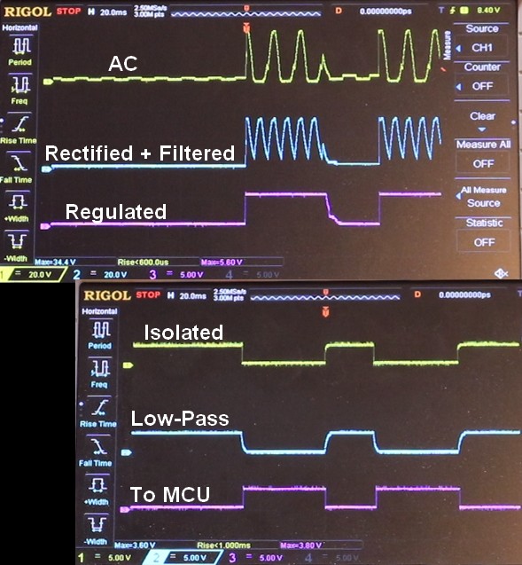
Let’s take a look at some of these signals on the oscilloscope:
I had to stitch together two oscilloscope runs to make this work, since the ground of the oscilloscope is different on each side of the optoisolator. so the first set of waveforms (AC, Rectified+Filter, and Regulated) are on the Seeburg side of the optoisolator and the second set of wave forms (Isolated, Low-Pass, and To MCU) are on the microcontroller side of the optoisolator. Note that these waveforms are scaled differently — the AC and Rectified+Filtered are plotted at 20 volts/division where all the other waveforms are plotted at 5 volts/division. I hope this illustrates how the input signal is conditioned into something that’s relatively pleasant for a Microcontroller to deal with.
The software to decode the pulses on the raspberry pi is beyond the scope of this particular blog post, though I do have it online in my github repository. Basically we look at the time between pulses. There’s a big gap between the last letter pulse and the first digit pulse, so we count the pulses before the gap and the pulses after the gap, and from that we know which letter and digit was pushed.
Controlling the coin switches
To control the coin switches, I used some 5 VDC dip relays.
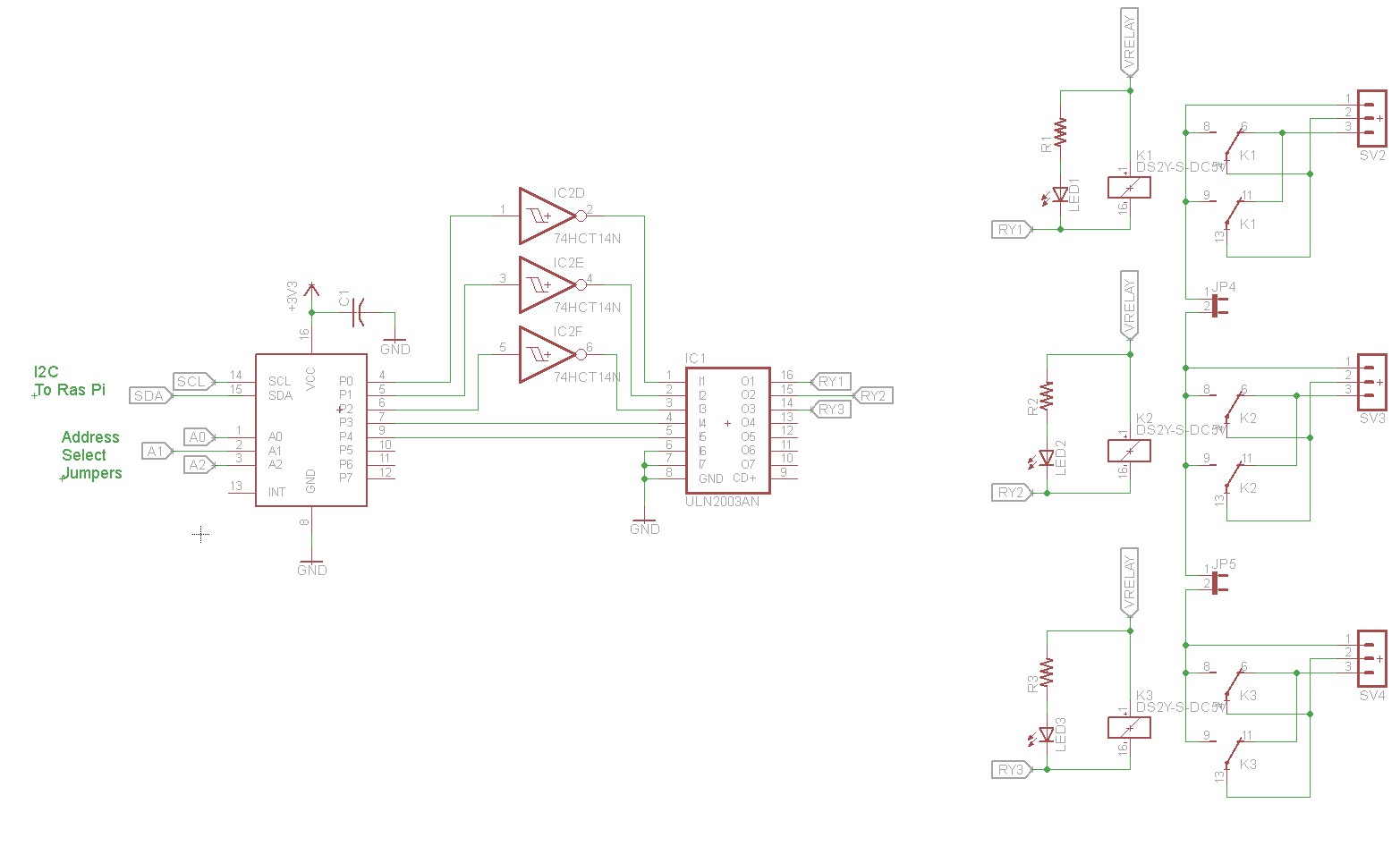
There are three relays, one each for quarter, dime, and nickel. These relays are driven by a ULN2003A darlington transistor array. I really like the ULN2003 and have used it in several projects where drivers are required. If you give one of the ULN2003’s inputs a high signal, then it will ground the resulting output. There are also protection diodes built into the ULN2003. It makes a perfect relay driver. Each relay also has a LED that can be populated to indicate status.
Driving the ULN2003 is a PCF8574 I2C IO Expander. Using the IO expander allows us to operate this whole board off of just two raspberry pi control lines — SDA and SCL, and those lines can be shared with other devices attached to the pi. It’s always nice to conserve IO lines, as you’ll never know when a project will come along that will cause you to run out. The way I designed this board, it can serve as a general-purpose relay board, and each relay can be used independently. I expect to be able to leverage it for other projects in the future.
You might be curious about the inverter gates between the IO Expander and the ULN2003. The IO expander’s default state on power-up is to drive all outputs high. This would cause our relays to energize until the pi sufficiently booted to turn them off. Using the inverters inverts this behavior, causing the default power-up state to be de-energized. Fortunately there were plenty of spare hex inverter gates.
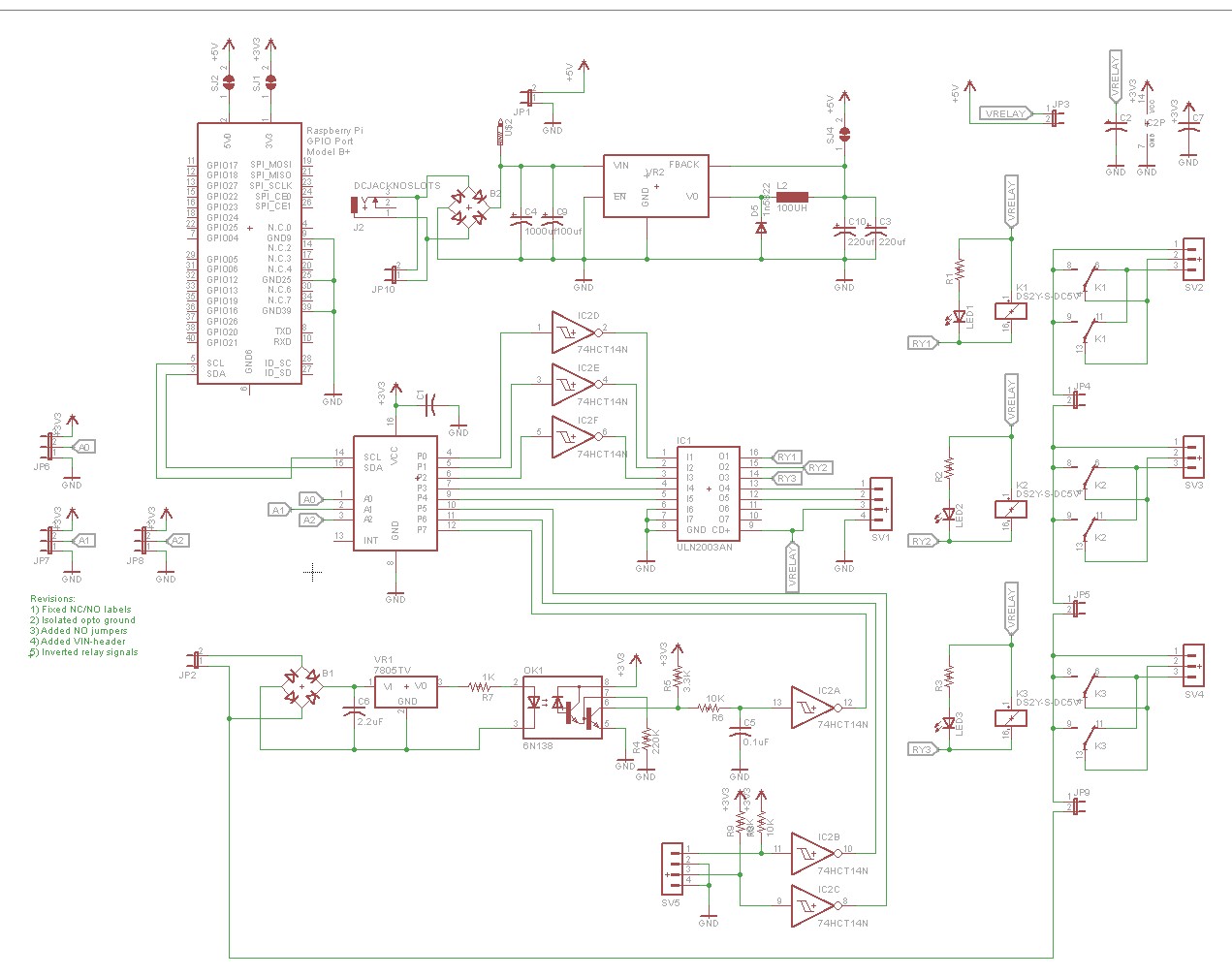
The whole schematic
Now let’s put everything together…
The seeburg input conditioning circuit feeds into the last IO pin of the IO expander. The IO expander’s pins can be used for either inputs or outputs, so we’re able to operate all of the IO on the hat from a single IO expander and therefore the single pair of SDA/SCL lines from the pi.
There were several unused pins on the IO expander and the ULN2003 so I put them to use. The IO Expander’s P3 and P4 go through the ULN2003 and are exposed on a pin header. They can be used for other output tasks, such as driving LEDs (with the appropriate dropping resistor, of course).
P5 and P6 are routed to another header via a couple of spare hex inverter gates. Pullup resistors are provided, and these may be of use as button inputs.
At the very top of the schematic is a switching regulator. I like switching regulators due to their efficiency and I often include this particular regulator in my projects. It allows us to power the pi and the hat from the same 25 VAC that powers the Seeburg.
Implementation
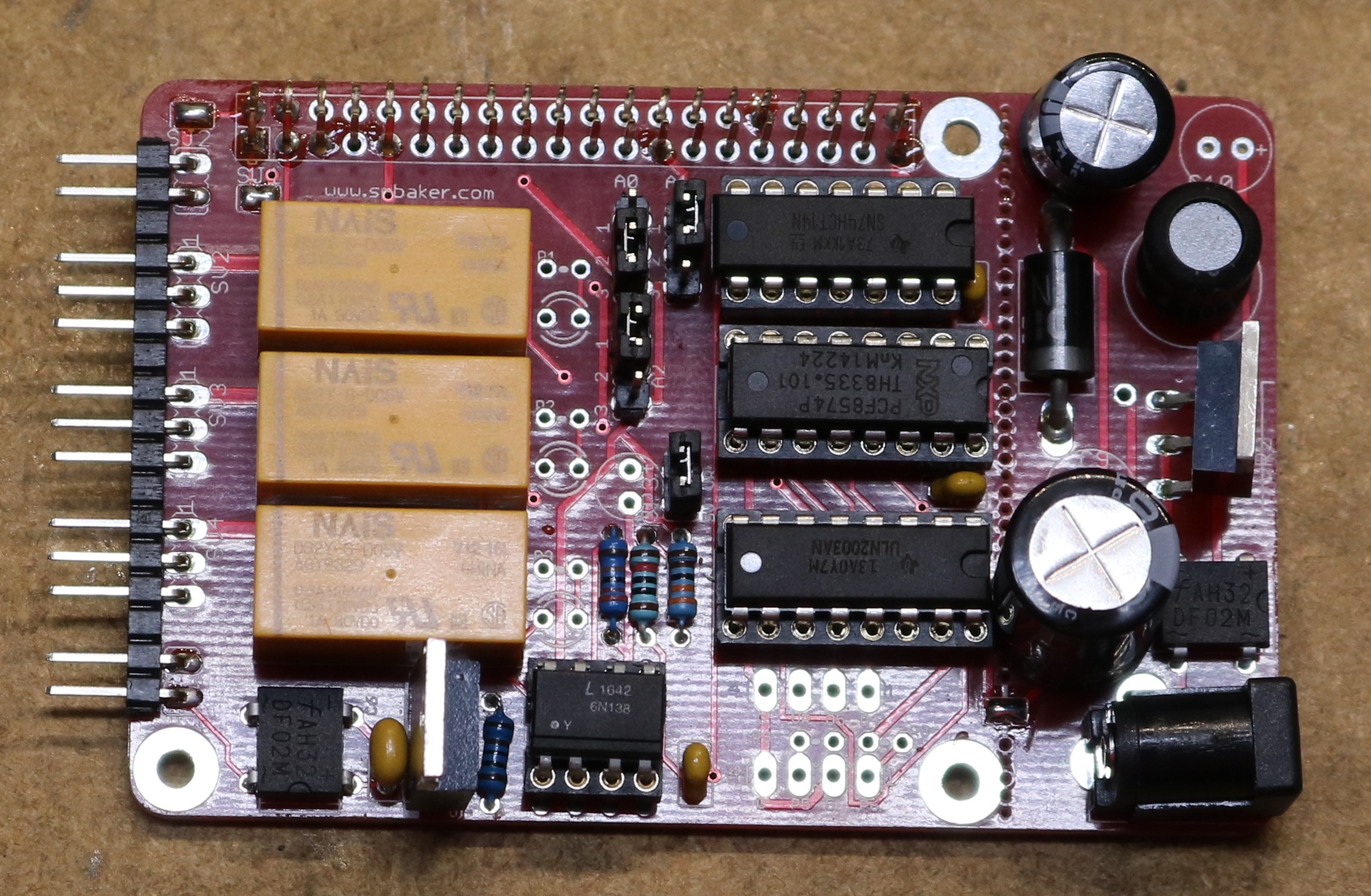
I used Eagle to create the board design and had it fabricated at Osh Park.I made two revisions of the board, below is the first revision:
The first revision had a few minor mistakes and lacked the inverter gates between the IO expander and the relays (you can imagine my surprised when I hit the power switch the first time and all three coin solenoids engaged at the same time). The second revision fixes this issue, as well as adding a few minor improvements, like jumpers to tie the NO lines of all three relays together.
[ Insert Picture of Revision 2 Here — as soon as I remember to take one! ]
Testing
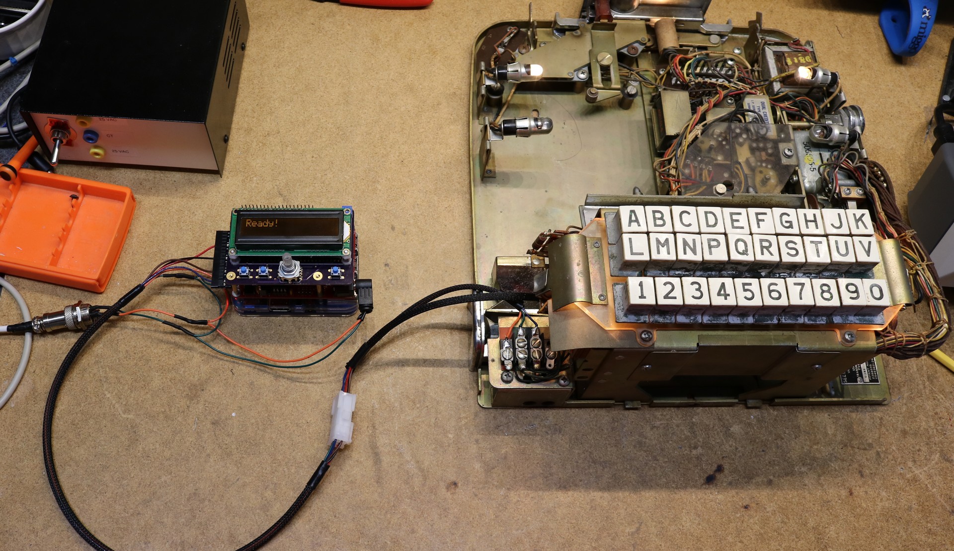
Here’s a picture of me assembling various parts together on the bench and trying out the decoder. There’s actually two hats stacked on top the raspberry pi — the first hat is the seeburg hat described above. You can’t really see it well, as it’s covered by a second hat, an LCD (or VFD) display hat from another project.
Assembling it all
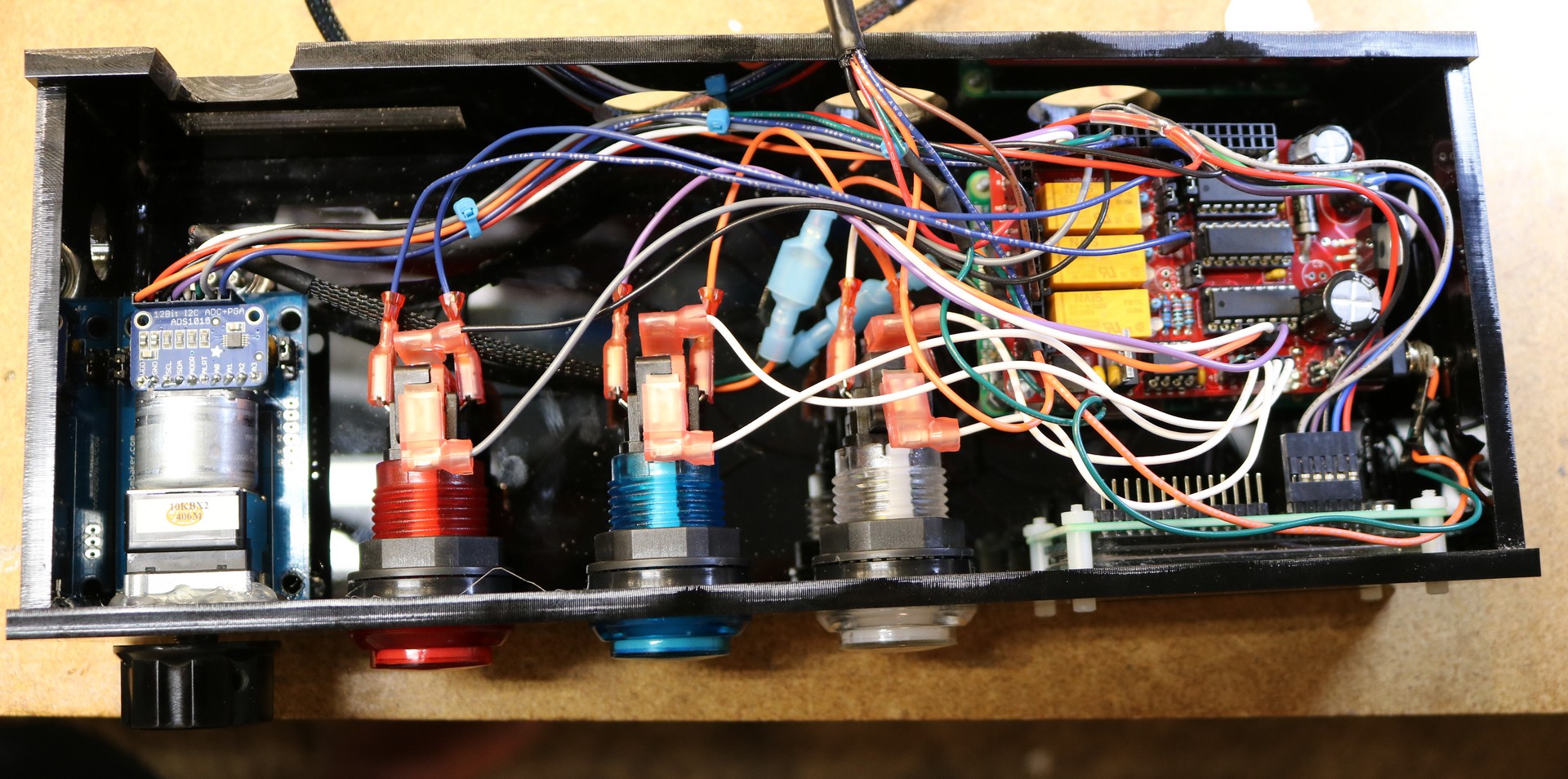
All of the raspberry pi parts went together into a custom acrylic case that I designed and had fabricated at Ponoko:
There’s a bit more to this than what I’ve described so far. On the far left is an Alps motorized potentiometer and the associated driver logic to go with it (h-bridge, ADC). On the right-front is a vacuum fluorescent display. The potentiometer can be used to control the volume of my stereo. The VFD displays the song currently playing. Both of these are outside the scope of this post. I’ve done a separate post on the VFD display, and the motorpot is something I will probably do a post about soon.
On the front are three illuminated arcade buttons that correspond to “Stereo Power”, “Song Skip” and “Insert Quarter” respectively. Two of them use the pin headers on the seeburg hat — the additional two ULN2003 outputs and the additional two schmitt-triggered IO expander inputs. The third button I wired to be always lit, and hooked its microswitch up to a leftover raspberry pi input.
Software
My software for this project is available on my github repo at https://github.com/sbelectronics/pi-seeburg.
Board ordering
The board is available on Osh Park by clicking the following button:
The same button includes a link to download the gerbers.


Great project. Do you have a BOM or parts list that I could use to order the parts? I ordered a bunch of circuit boards. The parts list out of eagle isn’t complete enough to order from. Thank you!
Hi, seems to be a very nice project. I’m interested.
Will this also work on a 100 selection unit? Important to know for me, before I’ll start ordering the board.
My Idea is that the selection made on the unit needs to be translated and send to the raspberry. So this is what this is doing.
This RPI should then pass the selection to another RPI, that play’s the selected record on my stereo system.
Thanks,
Johan S.
Try this BOM:
https://octopart.com/bom-tool/hPauNHDK
I took Scott’s OSH Park board, and learned enough about the Eagle software to make a stripped down version with just signal interpreter portion if anyone is interested: https://oshpark.com/shared_projects/gqbHSuvo
I had no experience with small electronics and little experience with RPI, so this has been a fun learning project.
Hey there. I am about to order the board from OSH park. Just wondering if you had a photo of the v2 board?
Hello, Thanks for posting this. I purchased a set of your version 2 pi seeburg hat version 2 boards and I’m having a little difficulty locating where all the components are to be located. Would you by chance have a photo of the final v2 board with components?
Hi Scott and Andrew, thanks for sharing this stuff. I have realised my own project using many of your ideas. https://github.com/Abac71/Seeburg-IO
I purchased a Wurlitzer 5250 wall box a year ago and not been able to have it operate at all. The seller refuses to stand behind his product but I am determined because of the time and money I have into this I would like to have it properly operating. Are you able to take on this project? I have the loaded MP3 player and transformer.
763 442 6121
Hi Scott and Andrew,
A couple of days ago i bought a wallbox seeburg 3wa. I started with your project.
I am not so good with the RPI 3b but i was able to download the SW from the github.
By checking the SW I had some issues with the print command in the seeburg.py script the following signs ( ) were not used.
The questions i have: Could you verify if the SW on the github is the right and working SW? Thank you very much. Regards Sebastian Vos
Great project. I’m going to attempt it myself. Hopefully learn a bit.
Ordered the PCB and it looks strikingly similar to the v1 board and you have not posted the v2 picture, yet. How do I know I have the right revision?
When you say “call an API” to play music, am I correct it is the RPi that is the MP3 player?