I built my own 5200 controller:
Purpose
There’s several different options you can use for an Atari 5200 controller:
- The stock controller. It’s non-concentering joystick, mushy fire buttons, and general reliability issues make it kinda suck.
- The masterplay clone. There are various adapters for using digital joysticks, like the common Atari 2600 stick, on the 5200. The drawback is that you lose analog capability. For more 5200 games it doesn’t matter, but there’s a handful of games that aren’t fully/optimally playable with a digital joystick.
- The PC joystick adapter. Vintage PC joysticks, the kind with the 15-pin connectors, are analog. You can more-or-less use one of these with a custom Y-adapter cable. The advantage is that you get an analog stick that plays all games. The disadvantage is a somewhat ungainly configuration of PC joystick (for movement), 5200 controller (for keypad), and Y-adapter device.
The final option is to build something yourself, to try to do right what Atari did wrong.
All about joystick potentiometers…
A common way of reading the position of a joystick potentiometer is using an RC circuit. If you take a capacitor and charge (or discharge) it through a resistor, then the time to charge (or discharge) a fixed value capacitor will vary with the amount of resistance. It’s simple for a CPU to measure that time and compute the value of the resistor. Substitute a potentiometer for the resistor, and you have yourself a joystick axis.
The value of the capacitor and potentiometer are important to the algorithm. Choose a different capacitor, or a different resistor, and the measurement will no longer correct.
Well, the Atari 5200 stock joystick uses a 500K potentiometer, and the commonly-available thumbsticks of 2018 use 10K pots. That’s a 50x difference. You can’t do a substitution as-is. We’re going to have to play a few tricks to make our 10K pot work.
Design
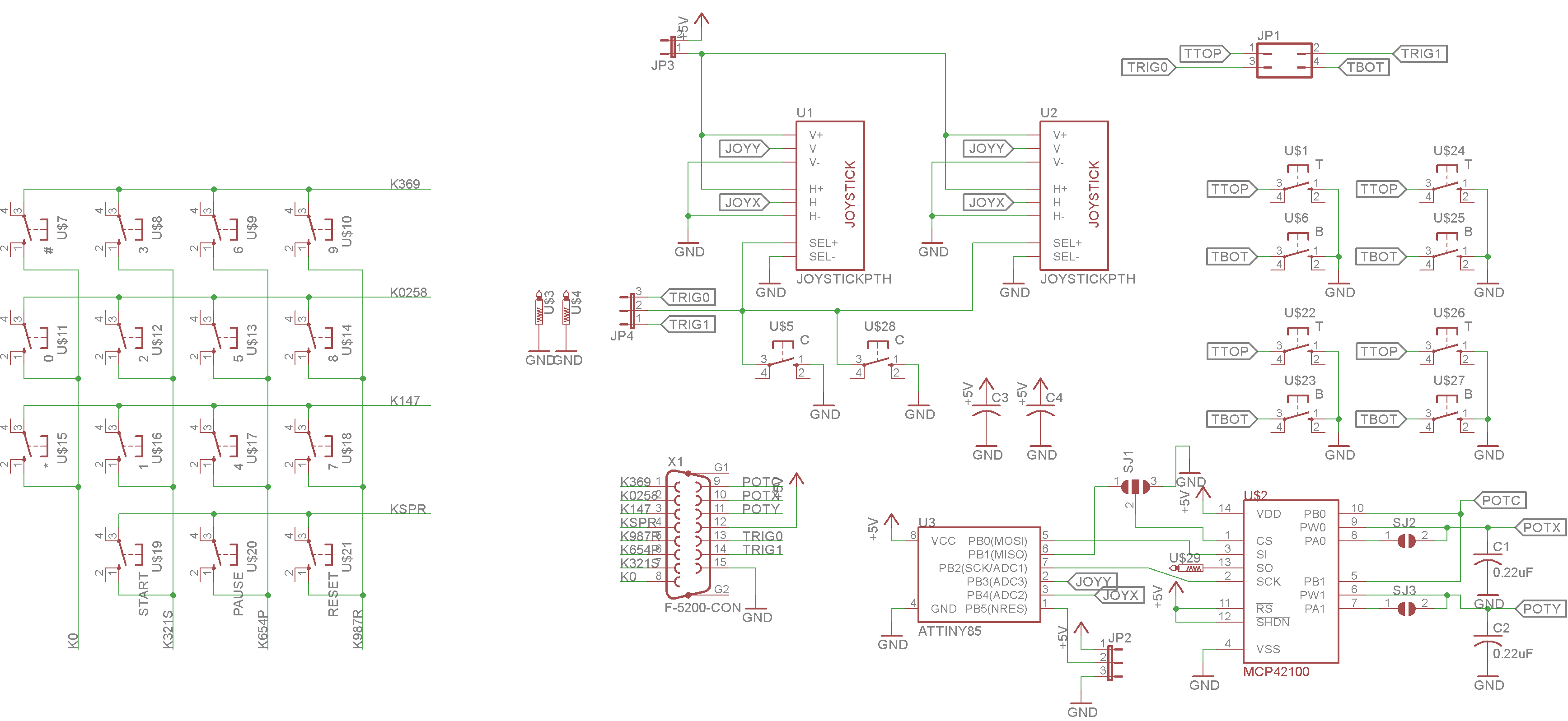
The schematic is presented below
The keypad is a standard matrix arrangement, right out of the Atari 5200 schematics. In a matrix keypad there’s a series of rows and columns, and each key connects some row to some column. The CPU strobes the rows (or the columns, depends on the implementation) and reads back the columns (or rows, depending on implementation) to see which keyswitch was pressed. So this part is easy. We just duplicate the Atari 5200 design using modern tactile switches.
“Multiplying” the potentiometer is a bit more work. We’re going to use an analog->digital->analog technique. An ADC will measure the position of the 10k joystick, and convert to a number between 0 and 255. A “digital potentiomer” (kind of like a DAC) will convert that number between 0 and 255 to a resistance between 0 and 100K. We’ve turned our 10K joystick pot into a 100K joystick pot. It’s not what we want, but it’s getting closer.
To make the 100K digital pot compatible with the 5200, which is expecting a 500K pot, we’ll just add some additional capacitance, about 0.22uF to the RC circuit. We can do this inside the controller, we don’t have to crack open our 5200 and mess with it. Remember, this all comes down to timing. Use a bigger capacitor, and you can get by with a smaller potentiometer.
Implementation
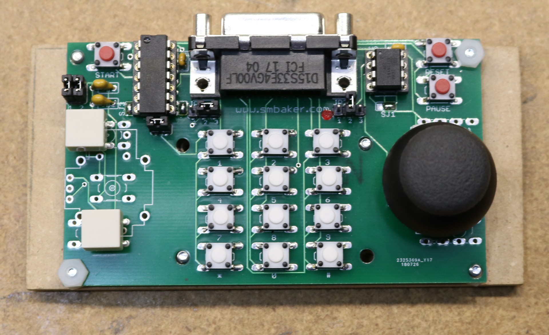
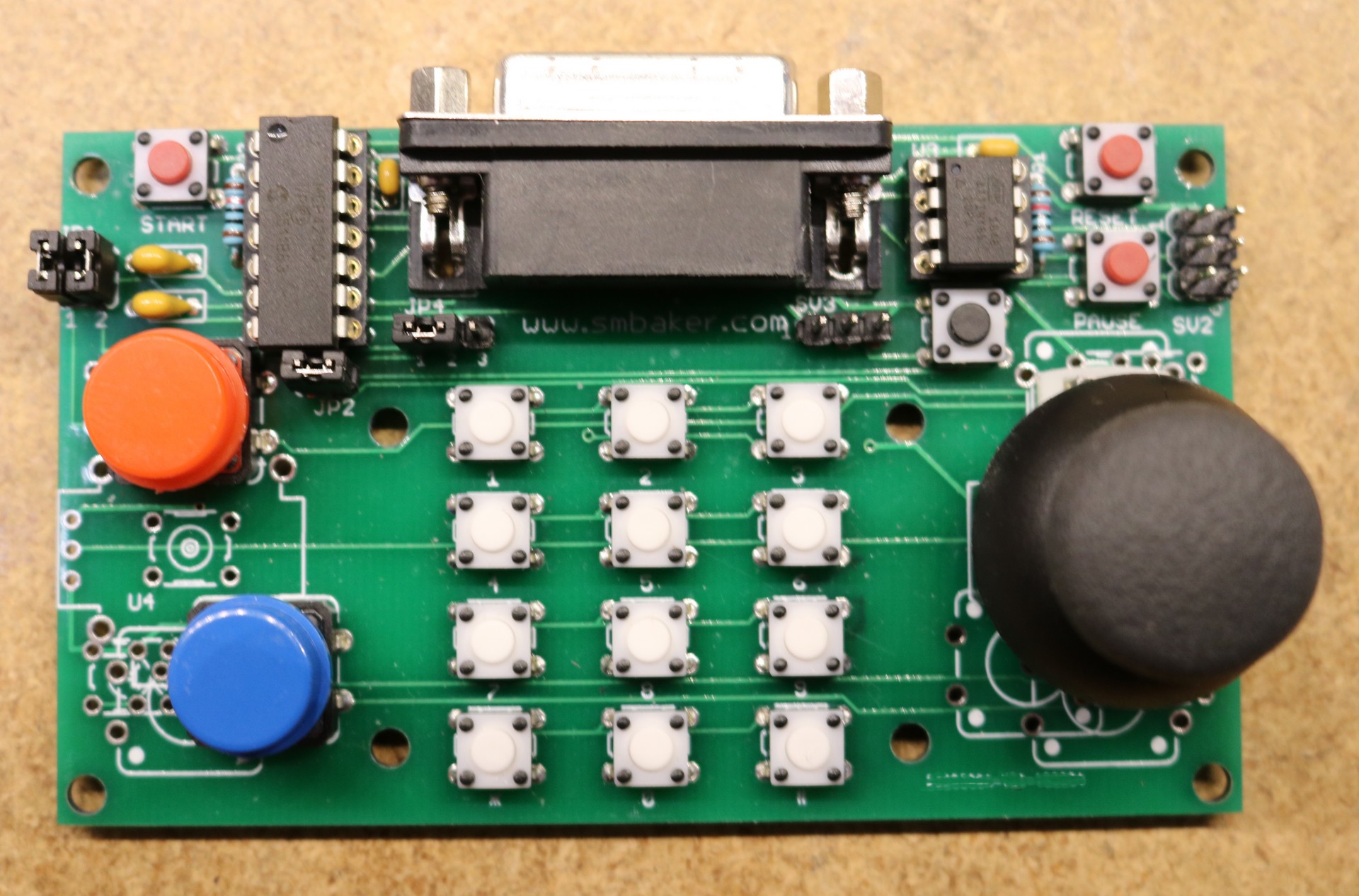
I had pc-boards fabricated and assembled my controller:
The thumbstick can go on either the left or the right (and the buttons on the opposite side).
Bill of Materials
| Part | Value | Quantity | Description | Source |
|---|---|---|---|---|
| C1,C2 | 0.22uF | 2 | Monolithic Ceramic Capacitor | Digikey, 490-7533-1-ND |
| C3,C4 | 0.1uF | 2 | Monolithic Ceramic Capacitor | Digikey, 399-4264-ND (possible substitute 490-9145-3-ND) |
| JP1 | 1 | 2×2 header | Digikey, S2012EC-20-ND (cut to size) | |
| JP2, JP4 | 2 | 1×3 header | Digikey, S1012EC-40-ND (buy one, cut to size for JP2-JP4) | |
| R1, R2 | 2 | 10K Resistor | Digikey, RNF14FTD10K0CT-ND | |
| SV2 | 2 | 2×3 header | Cut from same strip as JP1 | |
| JP3 | 1 | 1×2 header | Cut from same strip as JP2 and JP4 | |
| SH1-SH5 | 5 | jumper shunt | Digikey, S9337-ND | |
| U$2 | MCP42100 | 1 | Digital Pot | Digikey, MCP42100-I/P-ND |
| U$1,U$6,U$22-U$27 | 2 | Tactile switch, with plunger (qty 2) | Digikey, SW405-ND | |
| CAP1, CAP2 | 2 | Cap for fire button (qty 2) | Digikey, SW891-ND | |
| U$7-U$18 | 12 | Tactile switch, white (qty 12) | Digikey, 450-1649-ND | |
| U$19-U$21 | 3 | Tactile switch, red (qty 3) | Digikey, 450-1804-ND | |
| U1,U2 | THUMBSTICK | 1 | Sparkfun thumbstick (only populate 1) | Digikey, 1568-1526-ND |
| U3 | ATTINY85 | 1 | Microcontroller | Digikey, ATTINY85-20PU-ND |
| X1 | F-5200-CON | 1 | Female DB15 | Digikey, AE10929-ND |
| 4 | 0.100″ shunt jumpers | Digikey, S9337-ND | ||
| 1 | 8-pin IC Socket | |||
| 1 | 14-pin IC Socket |
You will also need the following misc items:
- chunk of hardboard, other other “backing” to make it easy to hold the controller (bare PCB is not comfortable to hold)
- 4-40 screws and nuts, to attach PCB to hardboard
- DB-15 extension cable, I recommend https://console5.com/store/neo-geo-aes-atari-5200-pc-controller-joystick-extension-cables-6-1-8m.html
- EPROM programmer to program the ATTINY86, I recommend a TL866 from eBay or a USBASP. If using a USBASP, please make sure that it is capable of selecting slow programming speed, either via software or hardware jumper.
Resources
- https://github.com/sbelectronics/5200-controller, github repository including code for the microcontroller.


Schematic says ATTiny85 but the BOM says ATTiny86. Oops? Nice work, I’ll steal this and integrate in my idea with using touch screen LCD as key pad (and SD card to store BMP files) so I could load custom key pad overlay that some 5200 games used. Still working on the LCD part, was going to figure out alternative analog replacement so your code saves me time.
I’d like to pick your brain a bit if I could. A friend of a friend built and assembled a controller built off this design. He has 2 5200″s, both a 2 port and 4 port. The controller works flawlessly for him. When connected to my 4 port system, the thumb stick is centered and not in a bind but acts as though you are holding it up and to the left. I can confirm that a original 5200 controller works without this issue. Would you have any advice to offer on this?
I begged and received an Atari 5200 system as a kid. Thank you for allowing me to share my favorite childhood pastime with my nephews!
Hi all. I’m building one of these controllers for my son’s birthday but having some trouble. Scott’s instructions state programming both the fuse.hex and 5200controller.hex files onto the attiny85 program memory. I’m using a TL866IIplus w/ XGPro. Can anyone offer some tips on getting both onto the chip? It seems like when I try to add the second file to the mcu the fuse.hex file is getting overwritten.
Sorry for the ignorant question but I am trying to get this project done before my son’s birthday which is coming up. Thank you for any advice.
Hi. I purchased everything on the bill of materials, but I don’t think you acylisted the tactile switch used for the red and blue buttons on rev 2. (The switches listed on the BOM are too small for this area of the PCB) Can you give me the part # you used for these, as well as for the red & blue cap switch covers?