In this video, I construct an Xi 8088 PC, based on the design by Sergey Kiselev:
Overview
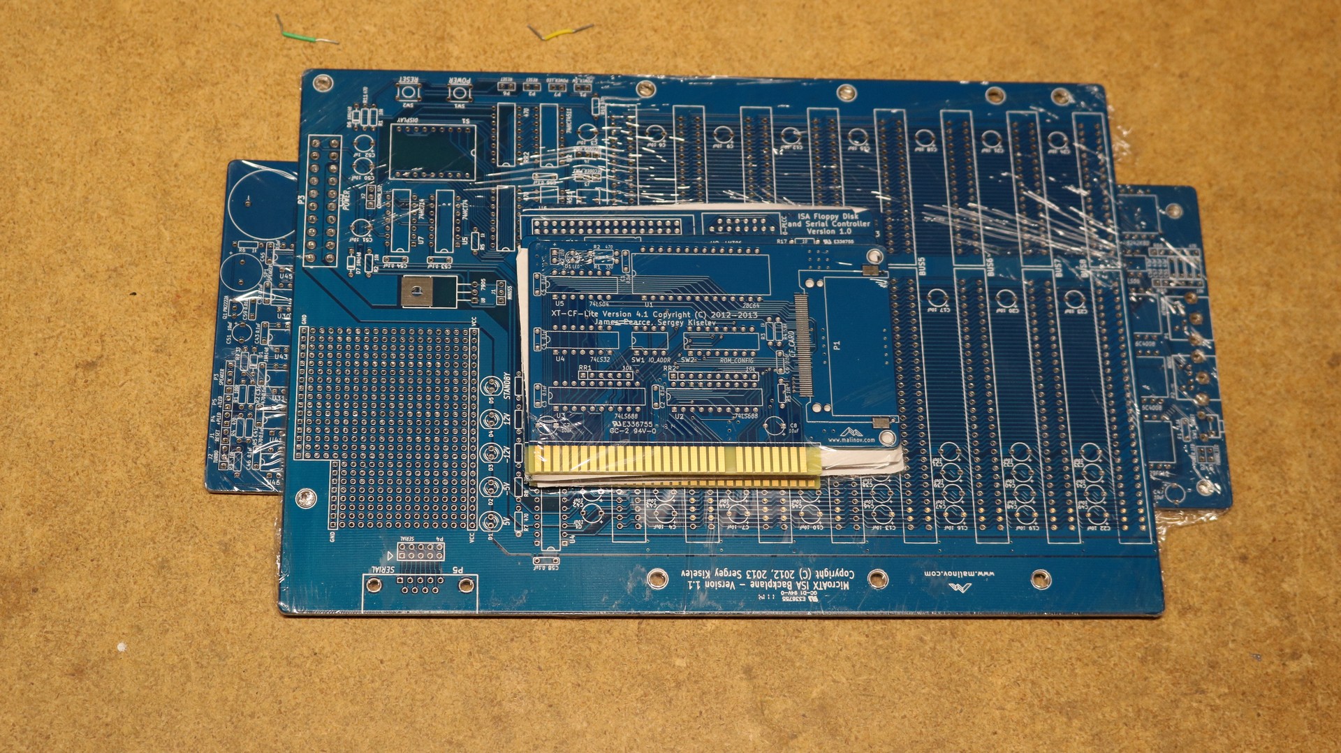
This was a long, involved project. I started out by ordering a set of boards from Todd over at the retrobrew forums:
These boards included:
- 8-slot backplane with BIOS POST code display
- Xi 8088 CPU board (CPU, RAM, ROM, Interrupt Controller, Timer, Clock gen, PS/2 keyboard and mouse, etc)
- OPL-2 Sound Card (AdLib Clone)
- Floppy and Serial adapter
- VGA card
- CompactFlash storage adapter
All of these boards are described over at Sergey’s website at http://www.malinov.com/Home/sergeys-projects
Building the backplane
The backplane was the first board I constructed. It has spots for eight edge card connectors, and BIOS POST logic. You get to choose which driver you want to use for the post display. Some drivers can display hex digits, some cannot, and some just display weird things instead of A-F. I chose the DM9368 since it displays hex characters properly. It also implements current limited, so one doesn’t need to have current dropping resistors. I found the DM9368 on eBay from a seller in China. Unfortunately, they turned out to be junk — one was DOA and the other two had a dead segment driver. I ended up ordering DM9368 from a US seller, and those ones worked.
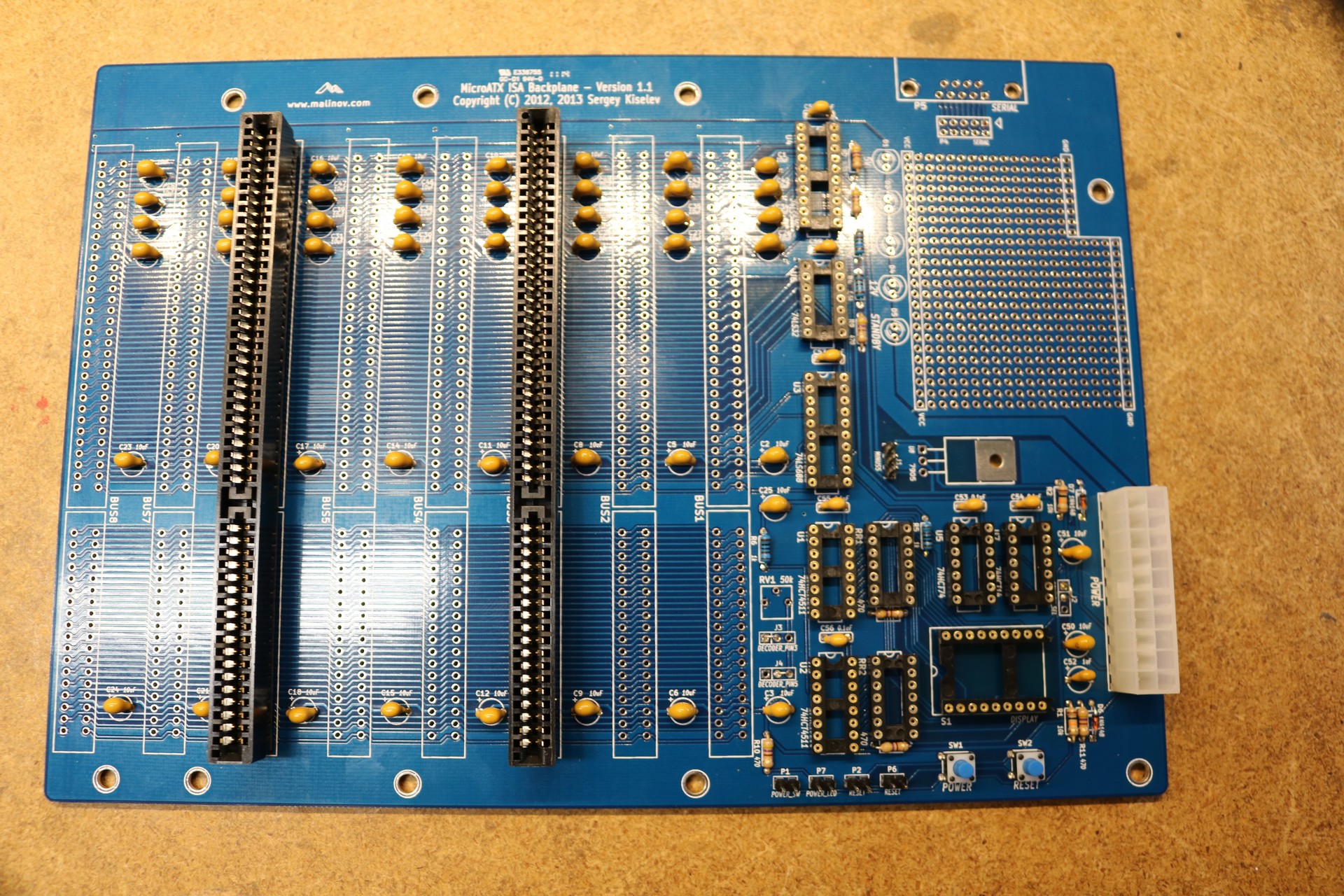
Here’s an early picture of the backplane. I started with just two card edge connectors installed, since I found edge connectors cheap on eBay and wanted to make sure they were decent before committing to soldering all of them:
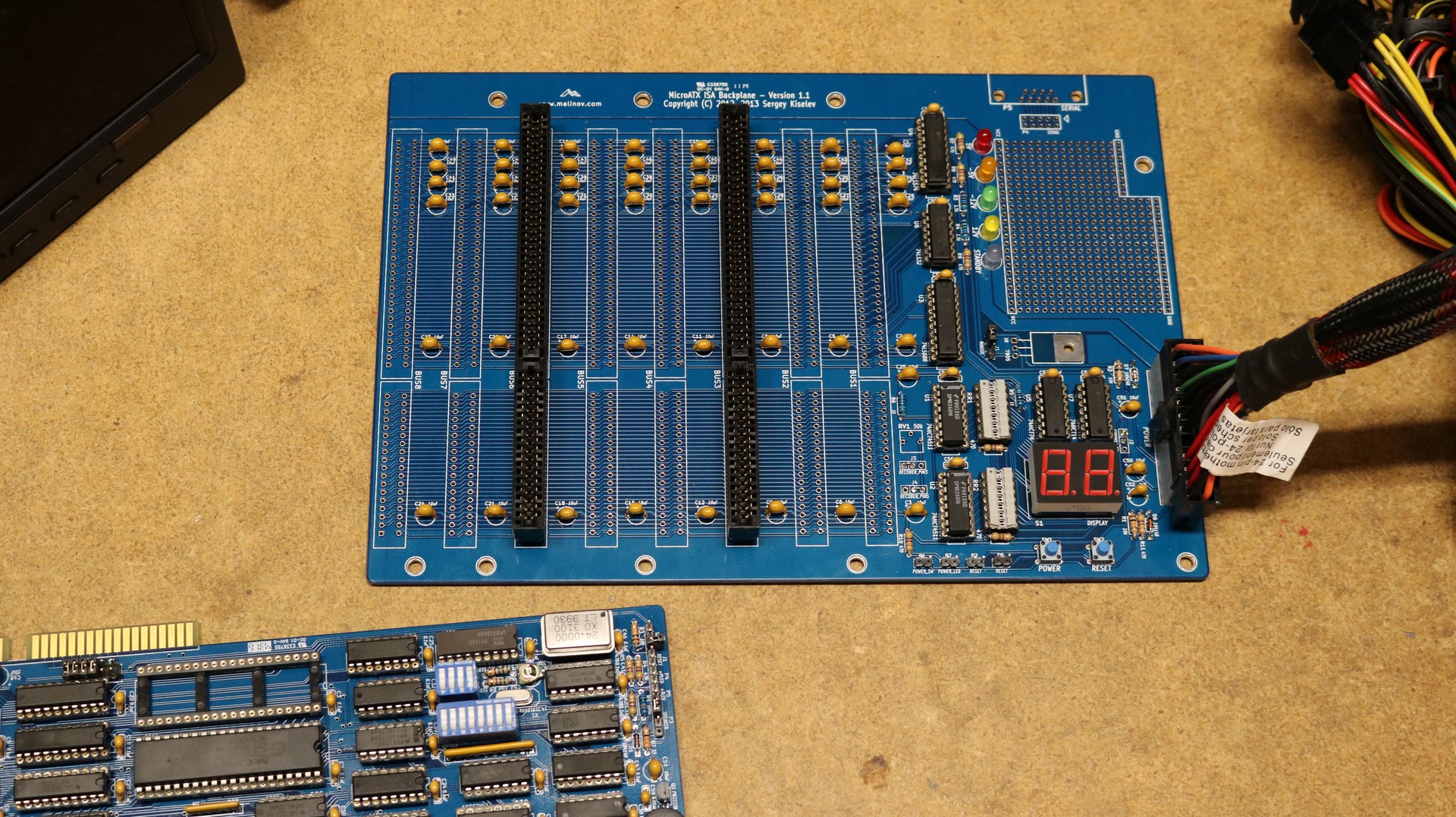
Here’s a picture of the backplane with the remaining components installed, right before I power-up tested it. Note that I had some 2×8 shunts that I installed next to the 7-segment drivers. You only need 7 spots, so I cut them down into 2×7 shunts. These shunts tend to come in handy.
Note that the backplane is 16-bit whereas the Xi 8088 CPU card itself is only 8-bit. The Xi 8088 CPU card does have the ability to pass some additional signals on the 16-bit connector. In particular it includes some additional IRQs, as well as MEMW, MEMR, and LA17-LA19.Using a 16-bit backplane also affords the opportunity to use a 16-bit CPU in the future should a 16-bit CPU board ever become available.
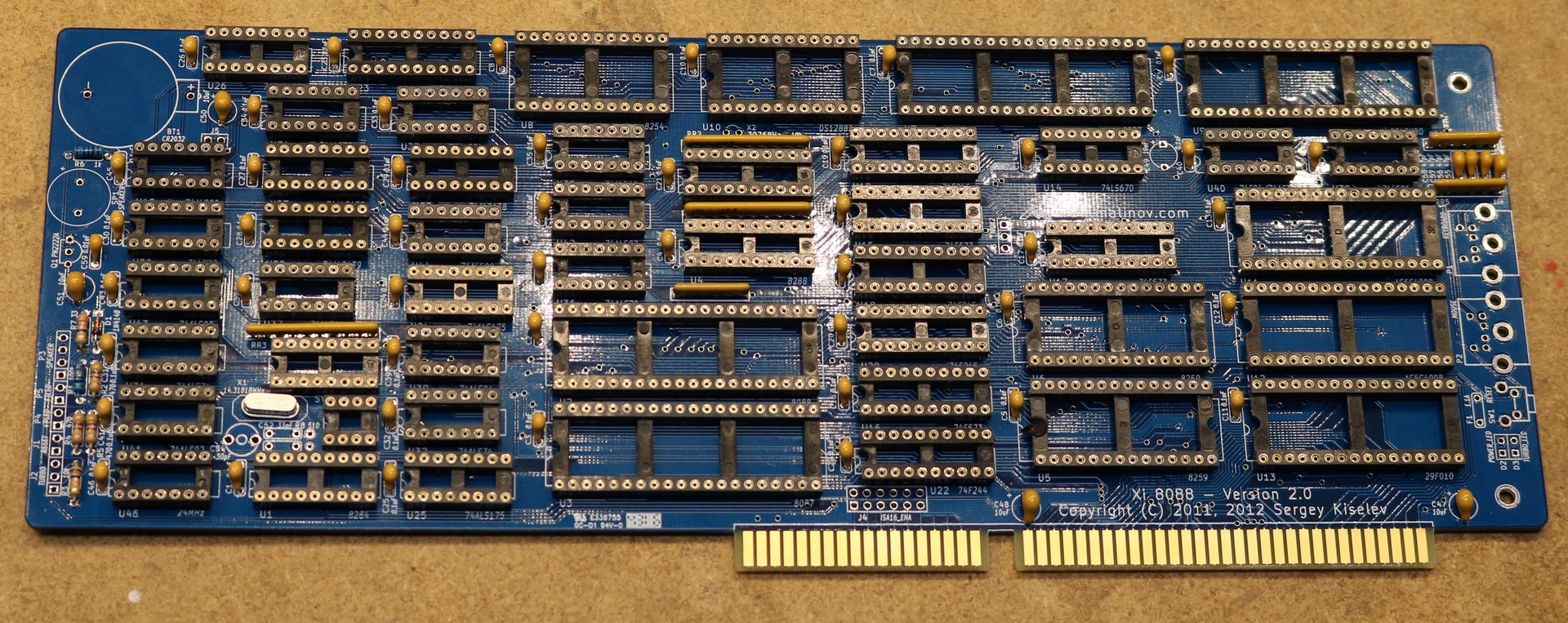
Building the CPU board
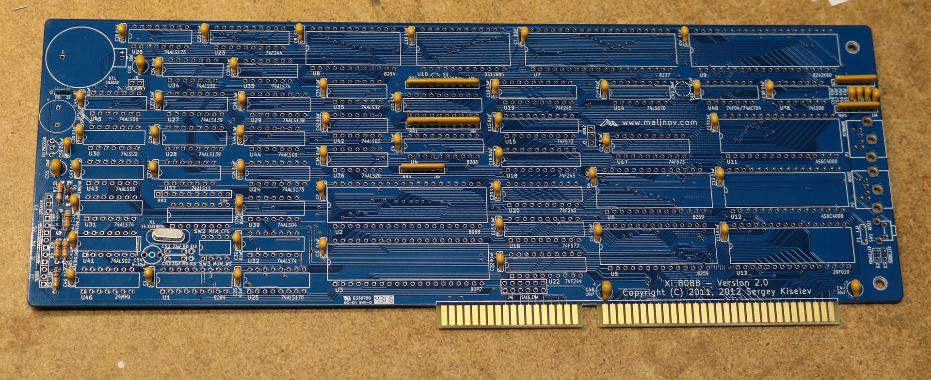
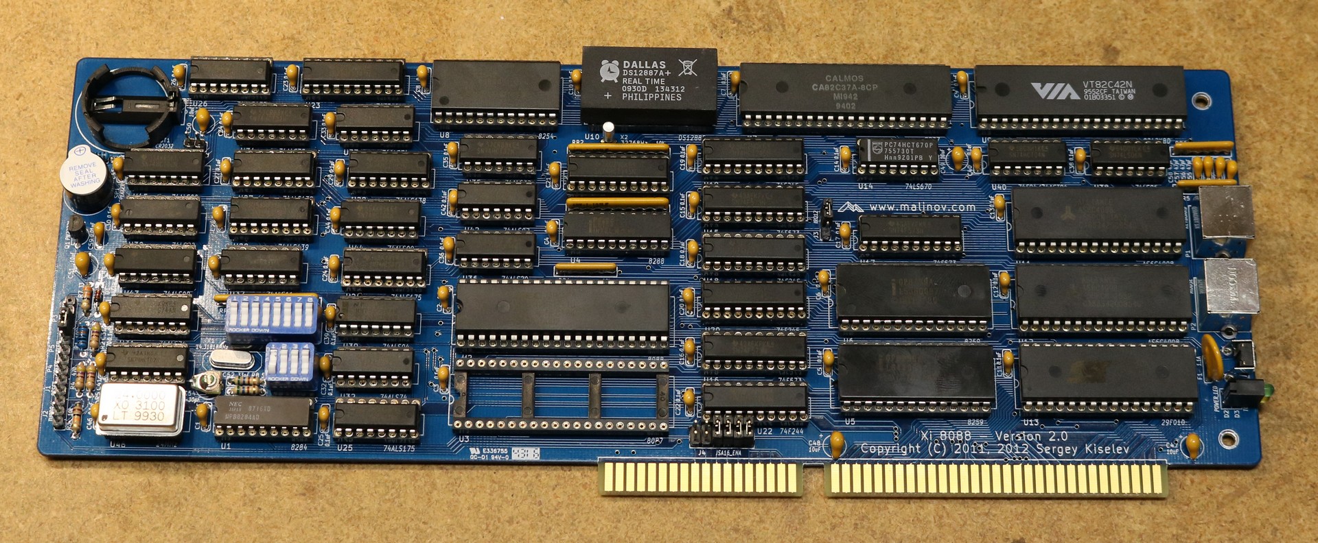
Next up was the CPU board. I started with the capacitors and SIP resistors, thinking they were shorter than the IC sockets and it would be easier to do them first. I was wrong. They were slightly taller than the sockets, and this caused me a bunch of unnecessary grief installing the sockets. Won’t make that mistake again!
You notice one socket is left unpopulated. That’s for an 8087 coprocessor. Back in my PC days, I never had the floating point coprocessor, so I never bothered. In this build, unless you plan on doing floating point computation, it’s just a waste of money and watts. For the CPU I chose a Nec V20. I’m not sure if I ever owned a V20 (I kinda think I did), but it offers a bit better performance than the stock 8088. I installed a 24 Mhz crystal to support a Turbo of up to 8 Mhz.
I used a DS12887A+ RTC, which doesn’t require an external battery or external crystal. I soldered in the 32.768 Mhz crystal and battery socket before I realized this. They don’t hurt anything.
I procured a TVGA 8900B card from eBay to use until I built my own VGA card. When looking for VGA cards, most are 16-bit. Make sure to get one that can be jumpered for 8-bit operation.
My first power-on test with the CPU didn’t go so well. The board made an obnoxious squealing sound. This is because I decided to save a $1.50 by using a speaker from the “junk box” rather than buying the recommended one. My “speaker” turned out to be a buzzer. Don’t do that. The other issue was that the POST display didn’t work right. This turned out to be because one DM9368 was DOA and the other had a bad segment. Buy your DM9368s from a reputable supplier.
After fixing these few issues, I managed to get it powered up and saw output on the VGA. The Bios worked. The keyboard worked. I couldn’t boot yet, because I didn’t have a storage device.
Choosing a case
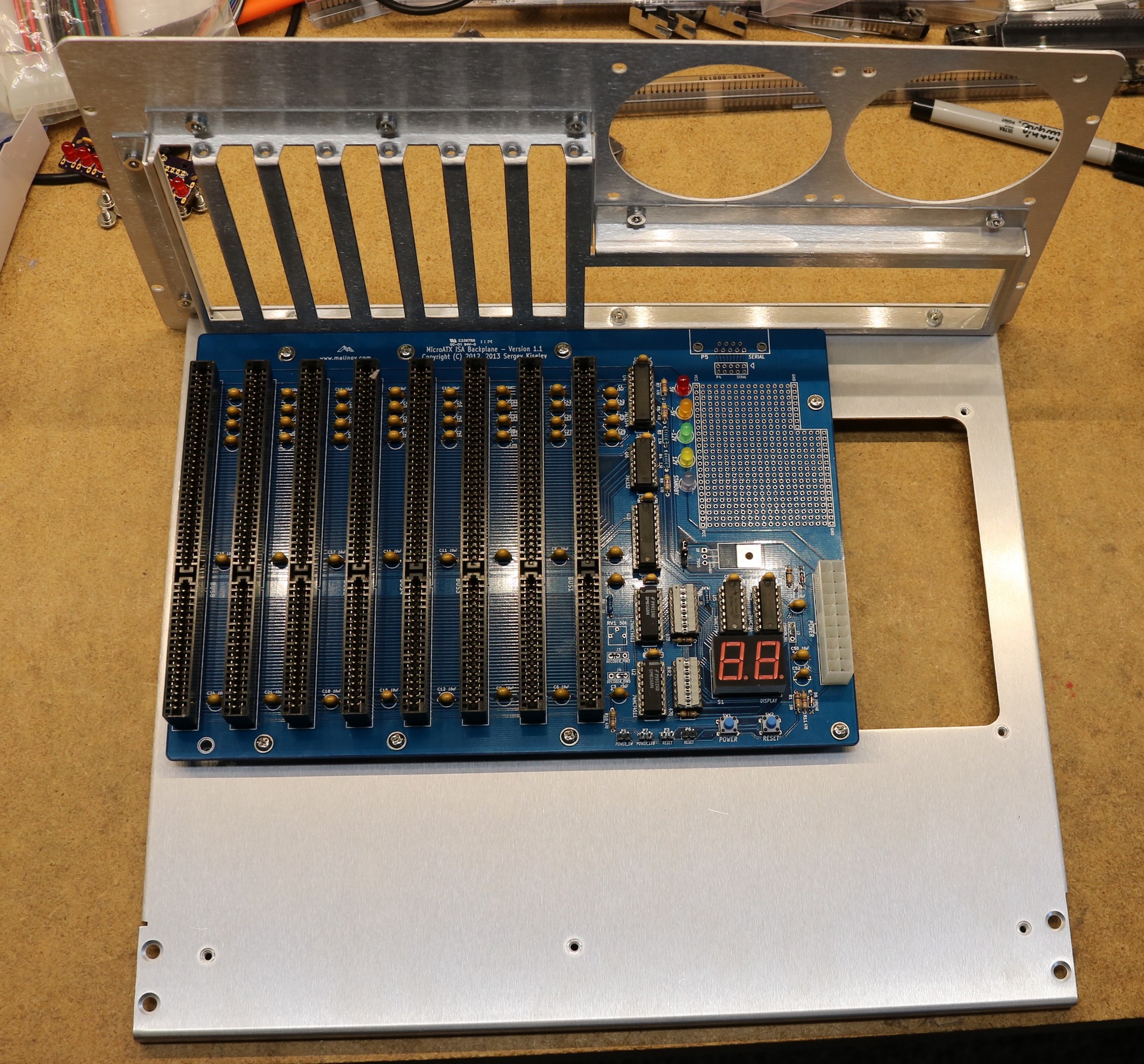
I felt really concerned about operating it sitting on the workbench, as one careless stumble could easy break something. While I did run a motherboard with no case back in the 80s, you feel a lot differently when you just spent hours soldering things together. So I decided to go about building or buying a case. Engineering the rear panel with cutouts for expansion slots seemed like a lot of work, so I settled on this “motherboard tray” by mountain mods:
I did have to modify the case slightly to accommodate the backplane. The issue is demonstrated in my video — the backplane lined up with the right edge of the case rather than the left, only allowing four slots to line up with the slot cutouts. I ended up drilling some additional holes and installing some additional studs. An easy-to-solve problem.
Building the floppy controller
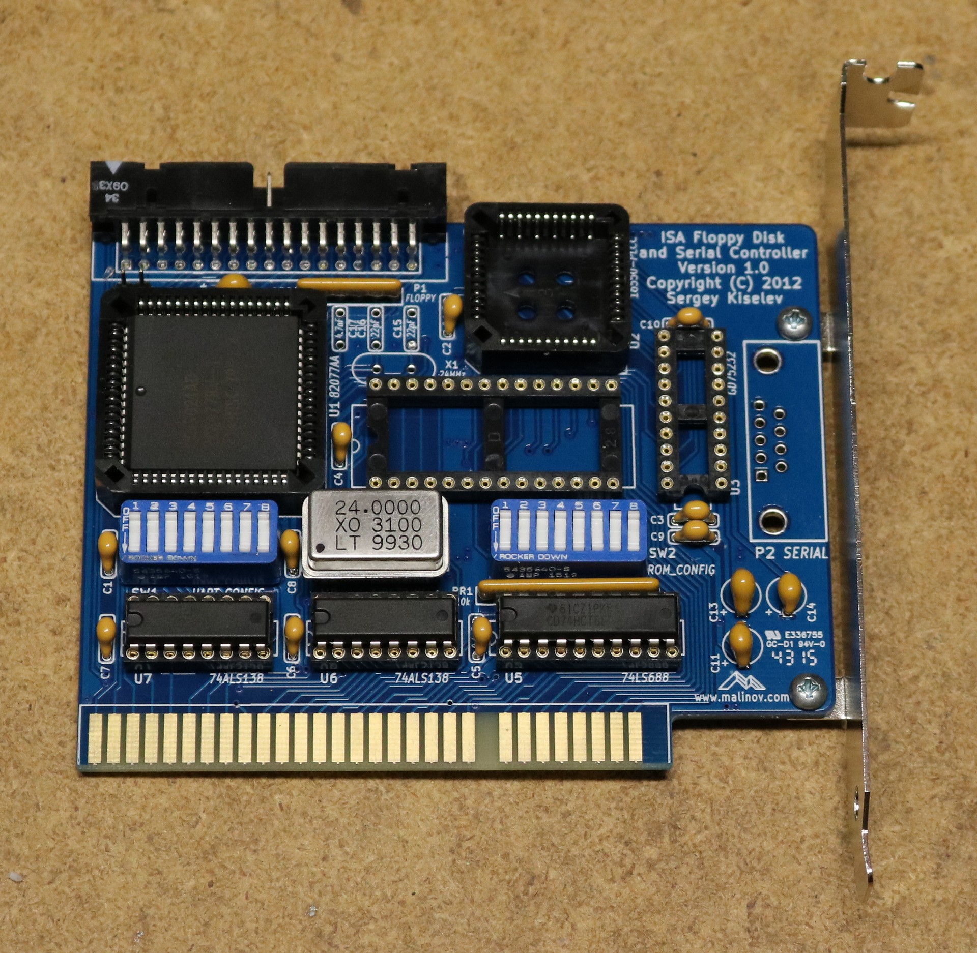
We can’t get very far without a storage device, so next up is the floppy controller:
The floppy controller that Sergey designed includes both a floppy controller and a serial port. I only needed the floppy controller, so I eliminated some of the parts necessary for the serial port. The board does have a couple of big imposing-looking PLCC sockets, but they are through-hole sockets and not that difficult to solder. If you can solder a through-hole DIP socket, then you can solder a through-hole PLCC socket.
A minor complication was that I didn’t have the needed 24 Mhz crystal. I did, however, have some 24 Mhz oscillators (whenever I buy something, I always buy two or three, to have spares). I put the 24 Mfz oscillator in the serial port’s oscillator socket, and installed a jumper wire (hidden behind the board) plumbing that oscillator through to the floppy controller. It work fine and was a good hack until I got around to ordering some 24 Mhz crystals.
After that, I booted DOS 3.31 from a floppy. It worked out fine.
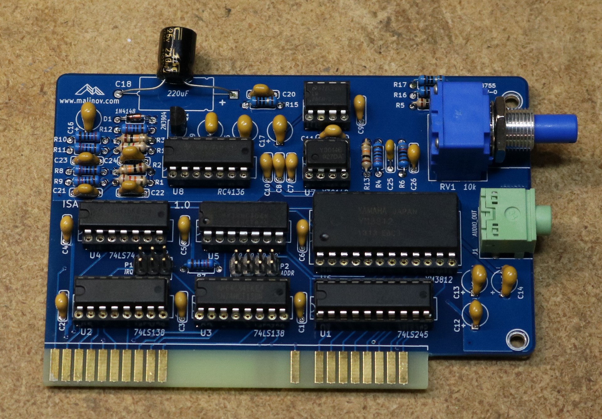
Building the OPL2 sound card
Back in the day, the first card I ever bought was an AdLib sound card. This was before the popular Sound Blaster cards. I was happy to see that Sergey had designed an OPL2 card, so I could experience FM synthesis again, on period accurate hardware.
The YM3812 and Y3014B chips are no longer produced, so I had to procure them from an eBay vendor. Surprisingly, they weren’t very expensive. The most expensive part on the board was the 10K bourns potentiometer. The audio amplifier has sufficient power to drive a small speaker, which I used in the demo.
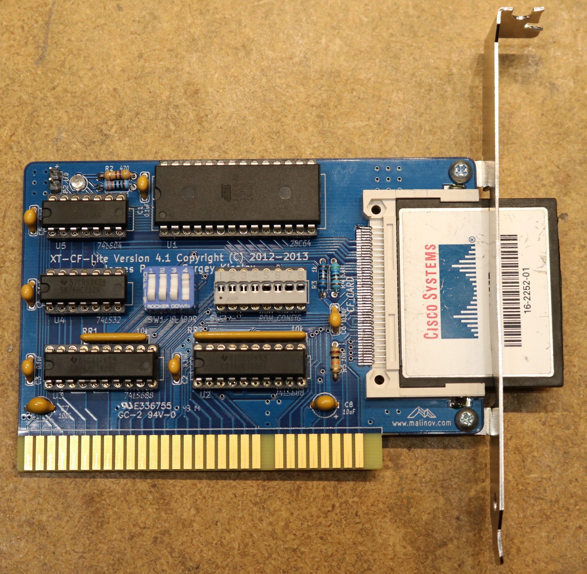
Building the Compact Flash storage card
So far, I had only been using a single 1.44 MB floppy disk. That’s pretty tedious, considering that many games of the period were too large to fit on a single disk. I tried running KQIV from floppies, and had to switch disks twice in the first few minutes. As such, I was anxious to construct a mass storage device.
You may notice that I have this odd grey thing where the ROM address selection dip switch is supposed to be. I ran out of 8-position dip switches, but I did have a stock of “programmable shunts”. You can think of a programmable shunt like a 1-time-programmable dip switch. It comes with all three positions wired across, and you punch out the positions you don’t want with a tiny screwwdriver. The only tricky part of the construction is soldering the compactflash socket, which is a SMD device. I used solder paste, a hot air iron, my microscope, and plenty of desoldering braid to get it right.
I used a 64 MB Cisco CompactFlash card that I bought on eBay. These cards seem to be fairly cheap and in wide supply.
I had some issues getting the card to function correctly after boot. The BIOS BIN file that I found on Sergey’s website would give me an “Error 3h!” message whenever I tried to boot from floppy. I rebuilt the BIOS from source and that issue was resolved. The BIOS does have a companion configuration utility that lets you program the BIOS for your system’s settings (number of adapters, type of adapters, port addresses, etc). It’s possible the original BIN file would have worked fine had I known about the configuration tool at that time. The folks over at the retrobrew forum were helpful in pointing me in the right direction.
Building the VGA Card
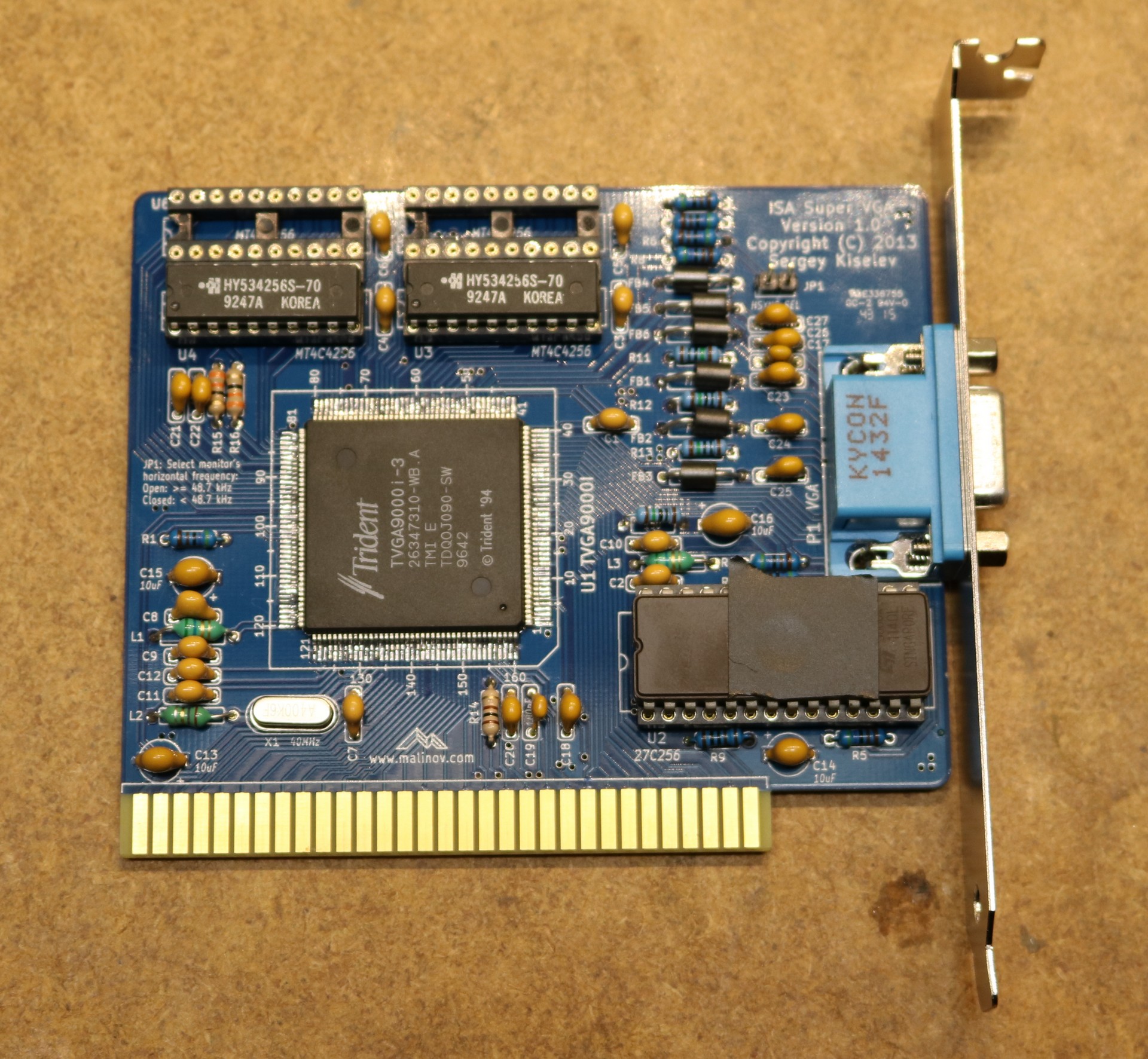
Although the Trident card I was using worked fine, the goal of this project was to build all of the cards myself, so I set out to construct the VGA card:
The TVGA9000i and DRAM chips do not seem to be currently manufactured and I had to source them from eBay. The single most challenging part of this board (and of this entire project) was soldering the TVGA9000i. It’s a large imposing SMD package, with tiny pitch and many pins. I had some issues with the solder paste I was using, and needed lots of cleanup. I went around numerous times poking and prodding each pins to make sure it was securely soldering, and testing each pair of pins to make sure there were no shorts. It took me a few hours to solder just this one package, though that may be a combination of the subpar paste and my subpar SMD skills.
The DRAM chips pictured are ones that I borrowed from an existing trident card. Two chips gets you 256K of video ram, and four chips gets you 512K. A set of chips has arrived from China, but I have not had a chance to try them out as of this writeup.
The VGA card worked perfectly the first time I tried it.
Closing Thoughts
This was a well-designed and rewarding project. The PC Boards are well designed and a joy to work with. The project is almost entirely through-hole components, so it’s something that is within the skill set of most people who would be tempted to attempt it. The only SMD components were the VGA card and the compactflash socket, and those two boards are optional.
Building a PC from scratch is not something I ever thought I would attempt due to the complexity of such a project, but it’s really not that difficult.
Where did you get the kit for this at? And do they have an 8086 variant so I could make use of the 16bit ISA slots?
There is no kit available, but you can but the PC-Boards. See “Retrobrew board inventory” at https://www.retrobrewcomputers.org/doku.php?id=boardinventory. Sergey’s website includes a BOM of all required parts. Most are available from Mouser, Digikey, and/or Jameco. Some of the older x86 parts are no longer produced and need to be hunted down on eBay.
You would not happen to know the part number for the LED display socket for the backplane you used would you? I am having issues finding a socket, and i would rather use the socket than directly solder it to the board.
Thanks,
Sean
Hi, any issues with your xi8088? Several of us over at vogons are having lots of issues with lockups.
(see last few pages of)
https://www.vogons.org/viewtopic.php?f=46&t=48477
feel free to push your joystick change back to my github so I can keep track of it (if you want that is) and keep all the xi8088 bios patches in one place.
I’ve got an old 80C188 eeprom dump that I’ve been trying to analyze, any suggestions on a disassembler/simulator?
On page 25 of ‘Debugging Embedded Microprocessor Systems Book’, it mentions a software called Visual-Probe Simulator but haven’t been able to find it!
https://books.google.com/books?id=qadDH_BX8boC&lpg=PA25&ots=fWJT_gSTiV&dq=VisualProbe%20Simulator%20software%20debugging%20embedded%20system&pg=PA26#v=onepage&q=VisualProbe%20Simulator%20software%20debugging%20embedded%20system&f=false
I have recently started experiencing issues, and I’ve joined the thread over at Vogons. It seemed like this build worked perfectly when I first constructed it, but lately has been acting up. Replacing one of the SRAM chips seemed to help, but it’s still not perfect.
I’m making a homebrew 8088, and I’m using NASM to write my programs. However, I have a strange problem. If I define any data in the data section, it makes my ROM file too big. But if I put it in the text section, despite fitting in the ROM, it doesn’t let the computer boot up. Would somebody please provide an entire working program that boots up the computer, because I need to verify that it works. I need to see the whole boot program to see what I’m doing wrong. I would greatly appreciate it…seriously. Thanks.
Thoose with random lockups; have you consider flux residue on the PCB after soldering?
Similar to the issue 8 bit guy was having with a PCB build he did.
Alcohol wipe down after assembly might be fix.
Michael
It’s been quite a while, but Michael, there’s 30 pages of forum members at vogons.org, many of them complaining about the same problem, instability on the Xi 8088. I think we can be confident the problem isn’t flux residue. Also, a while after your post, the “8-bit Guy” hyped up this “rare IBM Executive Workstation” then abused it like an amateur. The response was ugly and mostly undeserved. Yet, I would still hesitate to reference his repair techniques. Also, both you and I are “necroposting” a 2017 thread. Let me be the last post here, please.