I was so impressed with the Zeta 2 design when I built my floppy controller for the RC2014 that I decided to go ahead and build a Zeta V2 as well!
As you’re probably aware if you’ve read my previous blog posts, one of my recent hobbies has been retrocomputing, building computers based on the techniques of the 1970s and 1980s. Most of the projects I’ve built have been based on the RC2014, but I came across the Zeta 2 and decided to give it a go as well. The Zeta 2 is designed by Sergey Kiselev. There are PC-Boards available at the Vintage Computer Forum for $20 each.
The Zeta 2 differs from the RC2014 in that the Zeta 2 pretty much gives you everything you’re going to need (CPU, Parallel IO, Serial IO, Storage, Ram, ROM, clock, etc) all in a single PC-Board. As such, it’s relatively easy to assemble a fully-functional CP/M computer and has a working CP/M distribution that runs right out of Flash ROM. If you want to get a fully functional CP/M computer up and running quickly, the Zeta 2 is a great way to go.
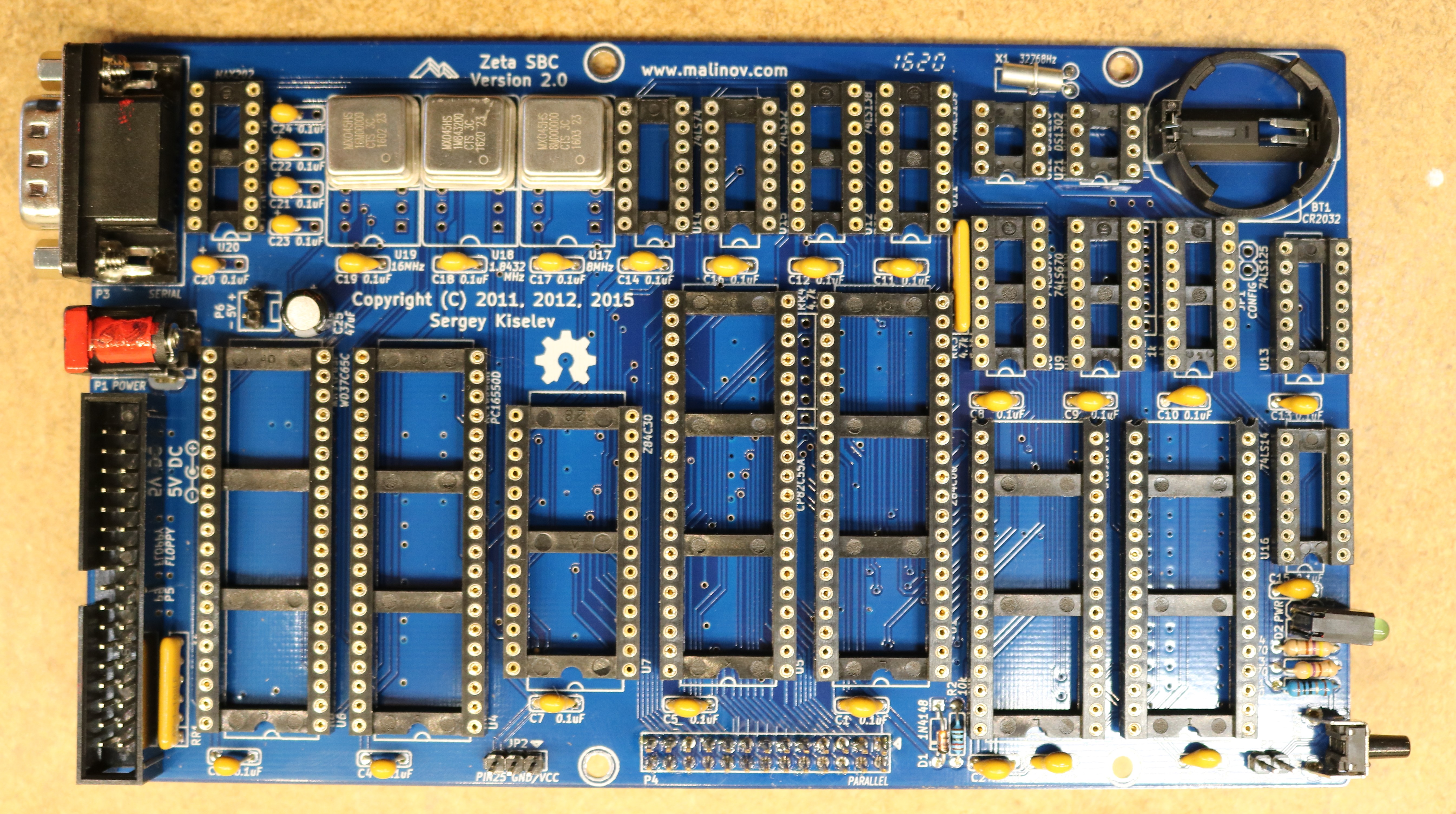
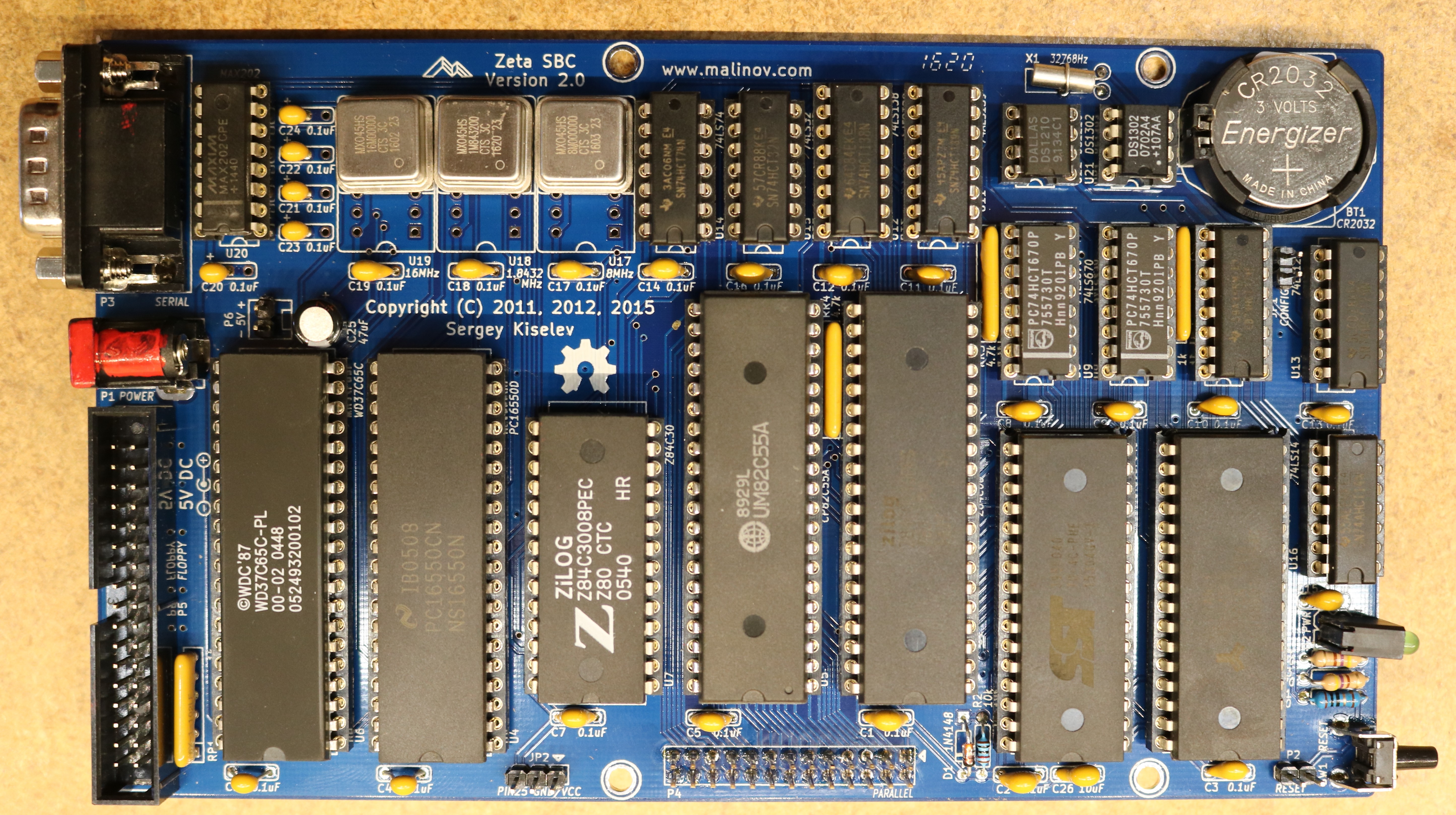
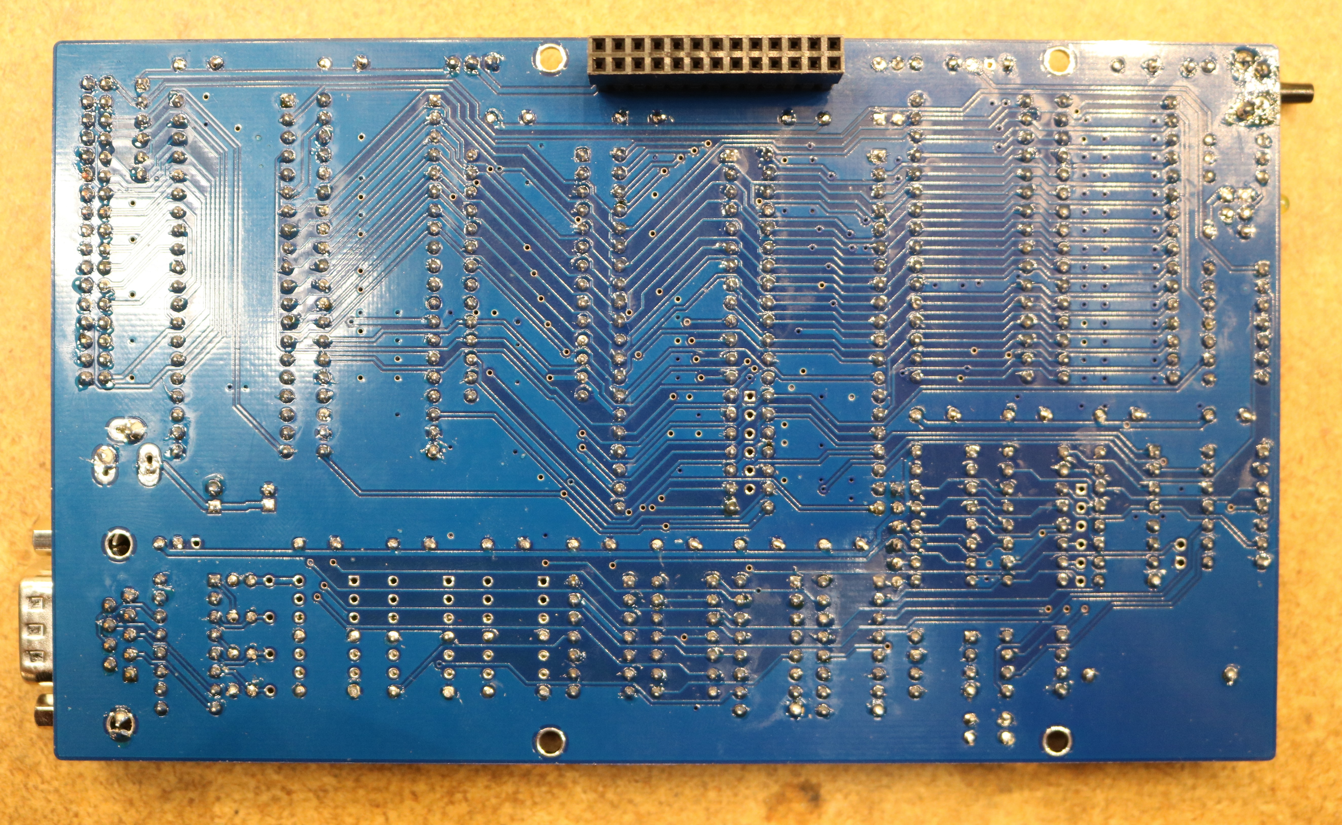
Here are a couple pictures of my Zeta 2 Build:
A few of the features of the Zeta 2:
- 512K Flash Memory, allows CP/M to be booted from Flash, and mounts Flash as a CP/M disk including many tools (assembler, editor, …)
- 512K Flash ROM, can be used as RAM Disk. Supports battery backup.
- 16550 UART provides a single serial port
- 8255 PIO supports up to three 8-bit serial ports
- Dallas 1210 Real-Time Clock
- WD37C65 floppy controller, easily supports 3.5″ PC Floppy Drives
Most of the ICs are easily sourced from places like Digikey or Jameco. A few of the more unusual ones, like the WD37C65 floppy controller, you may have to find at a site like eBay. Make sure to plan out your part acquisition accordingly (if you order some chips from eBay, note that suppliers are often in China and it may take a few weeks for parts to arrive).
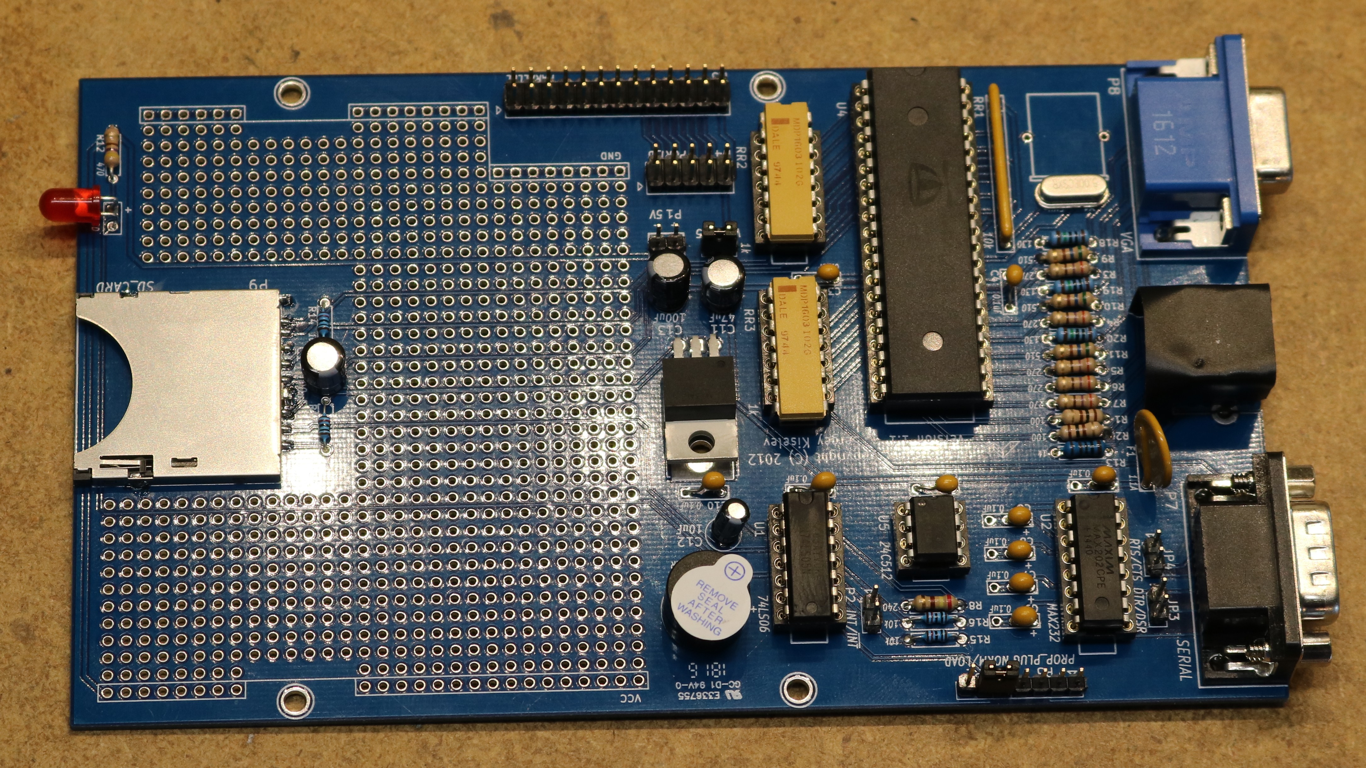
As you can see in the bottom view of the board, I used a stacking header. This allows the parallel port to be connected from either the top or the bottom. The reason for this is that there’s a companion board designed to work with the Zeta 2 called the ParPortProp:
The ParPortProp uses up the A and C ports of the Zeta 2’s 8255 PIO chip (leaving only 8 bits of PIO remaining), but provides you with:
- VGA Monitor Output
- PS/2 Keyboard Input
- SD-Card socket (mounted in CP/M as several 8 GB drives)
- Speaker
- Another serial port
The ParPortProp uses the Parallax Propeller micocontroller, a relative modern chip, so it diverges a bit from what we might consider classic retrocomputing. The Zeta 2 is still your “computer”, but the ParPortProp is acting as a terminal attached to the computer. This lets you connect a keyboard and monitor up to your Zeta 2, giving you a standalone computer than you can directly interact with.
The biggest disadvantage of the ParPortProp is the amount of PIO that it consumes. If you’re like me, and you like interfacing lots of things to your projects, then you might find the remaining 8-bits of PIO somewhat unsatisfying. The ParPortProp is completely optional though.
Conclusion
I really enjoyed building this kit. I was able to get CP/M up and running almost trivially. CP/M runs out of ROM so even if you don’t have a storage subsystem handy (floppies, SD Card, etc), you still have a fully functional computer.


Scott, thank you for this nice write up and the excellent video!
Where can one find the boards for the zeta2 and the paraport? Are either the floppy or SDcard directory structures compatible with DOS/Windows? In other words could I write a text file on my Windows machine store it on a floppy or SDcard then move the media to the zeta2 and read the file?
I am about to embark into retro computing, coming from an Arduino background. I have one part that puzzles me, as I am new to this. How does the ROM get loaded with the BIOS and CP/M? I remember back when I was little I had a Tandy 1000 RL which had MS-DOS 3.22 and Deskmate loaded into ROM but never knew how it got in there.
ROMs are usually programmed at the factory. For retro-computer builds, we typically use EPROMS (Erasable Programmable Read Memory) or Flash, which we can easily program, erase, and re-program ourselves. You’ll want to pick up a programmer. Check for a TL866CS on eBay.
thanks for this good guide.
One question, Where can I get the 2×13 female socket header(P4 connector) with such long pin? it seems not very common to find it.
Try searching for “stacking header”. I generally have a pile of them for various raspberry pi projects.
Where can I get a parportprop board? I built the zeta2 and its great but I would like to add the parportprop.
I would suggest checking the retrobrew board inventory at https://www.retrobrewcomputers.org/doku.php?id=boardinventory
Dear Dr. Scott,
Greetings from the Beautiful British Columbia. Thank you for your blog and youtube channel, I have been a fan for quite some time. I just finished building those two boards, the only thing missing is the DS1210+. I bought it on ebay, but did not arrive. So I bought it again (still waiting). Is there a way to test it without this chip? I tried turning it on, the power LED turns on but nothing work. I guess that it would not work with that socket empty… Also, is there a way to test the PPP board? This one is complete, connected the P1 pins to my power supply, but not even the led turned on. Maybe have to change jumpers settings, I don’t know…
Anyhow, Thanks again for your posts and videos!
Sincerely,
Rafael Silva
Hi I am in the process of bulding a Zeta 2 with Parportprop.
Several issues:
1) noise on CPU power rail but not on PSU – I suspect the high inductance (the long, very narrow traces arecauasing issues).
2) Data lines look horrible. – transistion high -> low is ok then it seems to capacitively drift to about 2V before switching to Vcc.
3) I can boot from ROMinto CP/M ok. However, Floppy disk is totally ignored, I have tried 3 different WD37C65 s (2 are WD37C65C the third is WD37C65B). If is fun FDU i get response back in trace. The power, data, FDC_CS are getting to the WD37C65 ok.
4) Parportprop seems to work as VGA and SD. SD is not bootable. – How do I copy OS from B: -> E: syscopy, SYSGEN fails. => SD slices are data only disks non-bootable.
5) I am having difficulty in programming the PPI port PB.
If I use Monitor O 63 C0, O 61 FF, O 61 00 Then my leds on PB work. If I try to do it from a program They turn on and then game over. I have also tried DI in code to lockout any interaction with ROMWBW changing PPI ctrl-word.
6) Are there any rules for using the PPI PB port as outputs?
Is there a shaddow location for the PPI CTRL-WORD that I also need to change to stop ROMWBW changin the ctrl-word + PB bits?
Any ideas?
Any body else had issues?
I am using Mouser supplied components from the BOM.
8 MHz Z80, 8 MHz CTC, 82C55.
Thanks
Peter
I have a different question – ParPortPro firmware
The supplied image is 32 KB but the device is a 64 KB device what is the 2nd half used for?
Zeta V2 SBC now working, it turns out that there was a problem with FDC in some versions of ROMWBW, apparently the wrong constants were used in the release build for a Zeta V2. ROM-v3.4.1-package is good.
Peter