In this post, I build a couple of different floppy controllers for the RC2014, and run CP/M on them.
If you haven’t read my other video on CP/M on the RC2014, please start there.
Motivation
Why a floppy controller when I have a perfectly good CompactFlash board? The floppy is more period accurate. If you’re building a retrocomputer, then speed and storage density are probably not your primary concern (just go buy yourself a raspberry pi instead!). The goal with retrocomputing is trying to reproduce the technology of a bygone era. For most of us that is probably the floppy disk.
There’s a number of possible floppy drives that can be considered, most notably the 8″, 5.25″, and 3.5″. Of these, the easiest to obtain drives and media for is the 3.5″. You might even have a drive laying around from a defunct computer. So let’s start with the 3.5″.
Design
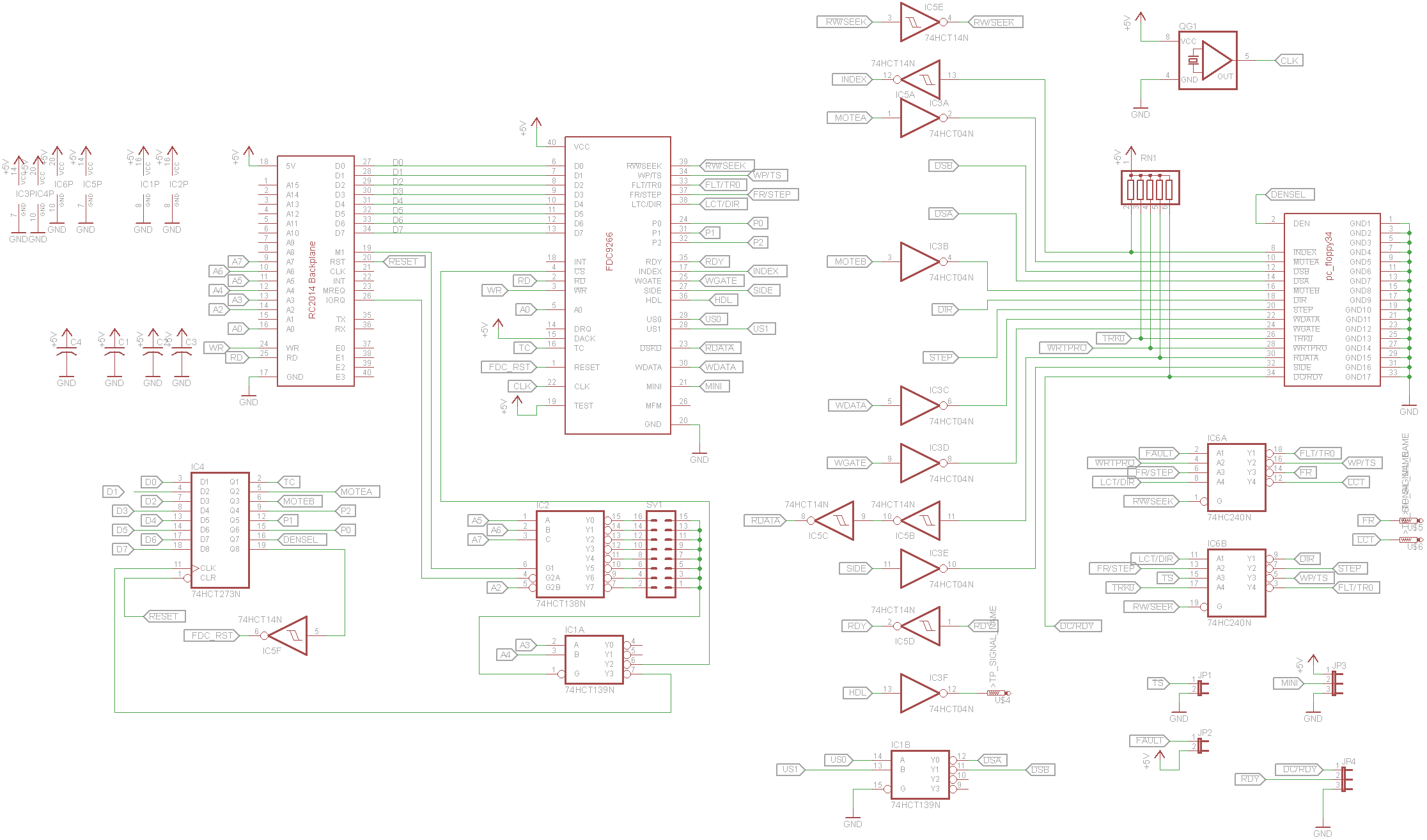
I started by looking on the Internet with a google search for “Z80 Floppy Controller”. The first result, which seemed very promising was the N8VEM DiskIo V3 board, which used the FDC9266 Floppy Controller. I adapted this circuit for the RC2014:
This design is based almost entirely on the DiskIO V3.
As you can see, the FDC9266 implementation is fairly complex. The guts of the circuit is the FDC9266 itself. The complication is that it uses active-high signals whereas our 3.5″ PC floppy drive uses active-low signals. This leads to a whole lot of hex inverters, on nearly every signal that goes between the controller and the drive. For outputs, we us a 74HCT04. For inputs we use a 74HCT14, which offers a schmitt trigger input. Note also the pullups on the lines from the floppy.
An additional complication is that five of the output pins of the FDC9266 (WP/TS, FLT/TR0, FR/STEP, LCT/DIR) are multiplexed. They have one meaning when seeking and a different meaning when reading/writing. This leads to a 74HCT240 being used to demultiplex these signals. The FDC9266 doesn’t give us control of the motors, and it needs some additional control signals (P0, P1, P2, TC). This leads us to implement a latch using a 74HCT273N. Finally, the FDC9266 outputs its drive selects not as individual control likes but rather as a 2-bit binary value, leading to the need for a 74HCT139 to convert those two bits into a set of drive selects.
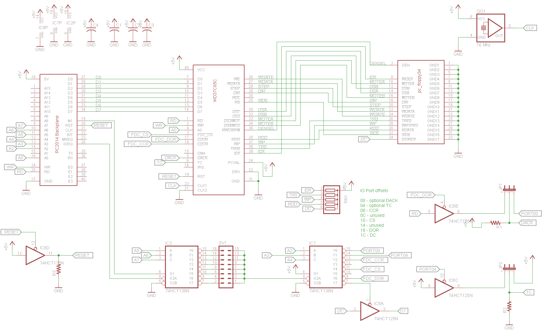
No sooner did I order the above design from Osh Park did I then stumble on a simpler design using the WDC37C65:
This design, based on the Zeta 2 Single Board Computer by Sergey Kiselev, fixes several of the gripes about the FDC9266. It outputs active-low signals so the plethora of inverters are not needed. It does not multiple pins, so the demultiplex chip is not needed, it has a built in DOR register so there’s no need for an external latch, and it outputs drive selects directly so we need no 74HCT139. The result is that many chips are eliminated.
I built and tried out both these designs, and I vastly prefer the WD37C65 due to the reduced complexity.
Implementation
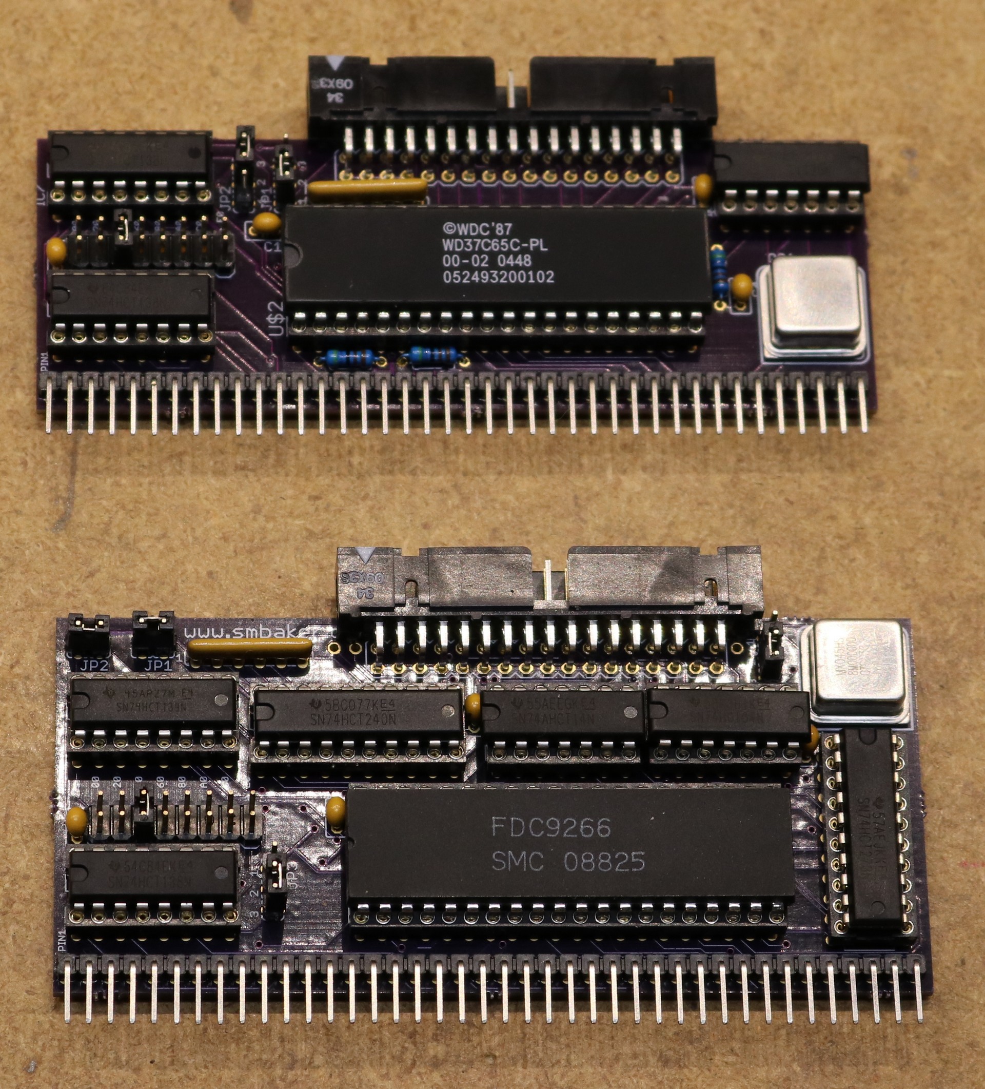
I ordered both boards from Osh Park and built them up:
The reduced complexity of the WD37C65 circuit is evident from the lower chip count. It’s not earth shattering, but any simplification is a benefit. In addition, having the DOR register built into the chip seems to make the programming easier.
Software
To make this thing work, I used the floppy driver from RomWBW. I modified the Grant Searle CP/M monitor, BIOS, and other assorted tools to use this driver, since Grant Searle’s CPM distribution has closer compatibility to the RC2014 I’ve built than RomWBW does. In the future, I’m probably going to transition my RC2014 over to RomWBW (future blog post!), but that’s going to take a bit of work.
I’ve committed the changes to the RomWBW driver to my github repo. There’s probably a few bits and pieces that I need to get together for anyone who wants to reproduce this — let me know what is missing if you try to build one of these yourself for the RC2104.
Using 8″ or 5.25″ floppy drives
I’ve managed to find myself an 8″ floppy drive on eBay and I’m going to give that a shot in a future blog post. There’s a little bit of complication due to a few extra pins (RWC = Reduced Write Current, and HDL = Head Load). Both chips have support for these pins, although in my WD37C65 board I failed to break the pin out to a pad (Bad! Always break unused pins out to a pad, as you never know when you’re going to use them!).
Using a 5.25″ drive will probably not be all that difficult, since we don’t have to worry about additional signals. It’ll just take some modifications to the CP/M bios to tell it what kind of drive (tracks, sectors, etc) to expect.
Board Ordering
As always, I’ve enabled the boards to be shared on Osh Park:


Hi Scott,
my rc2014 is running CP/M from CF-Card with your extension boards very well. I’d like to access a bunch of historical 3,5″ and 5,25″ floppies. So I build the WD37C65 floppy interface. Next step would to burn a new EPROM with the modified monitor to access the floppy interface.
Did you already release your modification of the monitor.asm for the floppy interface? If not, could you do it please? …or just point me in the right direction.
Kind regards,
birko
—
Hi Many thanks for this project – I have built the 2nd version (WD37C)- all appears to be working BUT I cannot seem to FORMAT my DOS floppy and get cp/m onto it. The FORMAT.com isn’t working. How did you format your floppies and get cp/m onto them please?
thnx
Colin
Sorry – I forgot to mention that I built
Z80 Retrocomputing 15 – CP/M on RC2014 Revisted, Using RomWBW
which works absolutely perfectly…..
Colin
Hi, Scott –
I’m assembling parts to build this board and wondering about the resistor values. Looking at Sergey’s schematic it looks like the resistor network (RN1) is a 1K part. Are the discrete resistors (R1, R2, R3) also 1K?
Jim
Colin –
You probably already figured this out, but just in case, here’s how to format and put CP/M on a floppy with the current tools:
This step formats the diskette:
B>FD.COM
(S)etup -> Unit 00, Media 01 (for 1.44M 3.5″ floppy), Polling=00, TraceLevel=00
(F)ormat -> (D)isk
Interleave=02
E(X)it (assuming no errors)
This step moves CP/M or ZSDOS to the diskette:
B>SYSCOPY C:=CPM.SYS for CP/M -OR-
B>SYSCOPY C:=ZSYS.SYS for ZSDOS
Then, answer “Y” to confirm your choice.
Once this process is done, you can reset and press 2 to boot from the first floppy.
Do you have a BOM for the board? I looked at Sergey’s BOM and I’m not 100% positive the 16MHz oscillator he uses is the same as the one you used. Yhe ‘pin-outs’ on his part seem to have different numbers than you have on your schematic. It’s the physicall size that concerns me. Would you have a DigiKey part number?
Hi Scott,
I see above where Jim Harre asked about resistor values, but I don’t see a response. I guess I have the same question about resistors and capacitors. I tried reading the color codes of R1,R2, & R3 on the photo of the boards, but found them very difficult to make out.
Any chance of getting a good BOM for all parts. It would make it a lot easier to figure out what was need to build one of these boards.
Thanks,
Steve G.
The resistors are all 4.6K. The oscillator is an MXO45HS 16Mhz. Checking my order history with digikey, it’s likely this one: https://www.digikey.com/product-detail/en/cts-frequency-controls/MXO45HS-3C-16M0000/CTX750-ND/1801865
Is the resistor network on the WD37C65 board 1k or 4.7k?
I receive my disk controller boards yesterday and will combine one with a Z80MB64. BIOS’s are fun. 😀
Mr. Baker,did you ever develops a driver for the 37c65 separate from romwbw? I’ve built your board and want to make a bios for the z80mb64 that for the board. That system’s does not allow for and and I’m having trouble finding a simple driver to adapt.There seems to be a lot of fluff in the end driver that I just don’t want to deal with so if you could give me a leg up I’d appreciate it very much.
I build the wd37c65 version and it works great! Im using it with an sc-126 and romwbw.
Thanks Scott for such a nice little board.
P.S. i want to try this with your sbc so publish the gerbers or project files pweeze.
Hey Scott, wondering if you ever got a chance to test the 8″ drive support? I am pondering to relive my early career by building an old-skool CP/M machine with 8″ drives. I like the simplicity of the WDC chip but I haven’t been able to find a clear statement whether these work with 8″ drives.
Hi Scott, I’ve got your WDC card up and working. To be exact, I can access the floppy with the FDU program. I have the ROMWBW 3.0.1 installed. But the floppy doesn’t show up in the device list on booting.
I struggle with the WD37C65 board. Does someone have it up & running. FDU can access the floppy drive, but it looks like there is a mismatch btw. /Motoron and /Drive select. I am afraid, I have a broken FDC device. The drive select outputs are always low. I think after RST they should be high. I would appreciate any hint.
Laszlo
Hi Scott, I see you made some modifications on the WD37c65 board. Refering to the schematics http://www.smbaker.com/wordpress/wp-content/uploads/2016/12/rc2014-floppy-wd-sch.png I hardly know what you mean with HL, DS, C, NC6. Could you give me help?
Thanks Laszlo
“Use this configuration for WD37C65 special mode:
842 – cut B, HL; short C head load from pin 18
stepper motor always energized
(short DS-near-J2 to only energize stepper motor on drive select)
Note: WD37C65 special mode polls drive readiness by asserting DS about 1000 times per second. If head load or stepper is drive by DS, then they will sing.
Modifications to 34-50 adapter route NC6 to HL
Modifications to floppy controller route HL to NC6