The Masterplay was originally a device that allowed Atari 2600 digital joysticks to be used with the Atari 5200. In this post, I describe a masterplay clone that I created.
Purpose / Introduction
The analog controllers for the Atari 5200 are (in)famous for their poor feel and performance. The analog stick, while a really good idea at the time, doesn’t have a decent return-to-center feature. As the vast majority of the games for the 5200 do not make use of the analog capability, this feature while innovative, is far more of a drawback than a benefit. As such, there have grown to be a number of different solutions for connecting Atari 2600 sticks to the 5200.
Some of these solutions can completely replace the 5200 controller. Other ones feature a Y-cable that allows you to continue to use the original 5200 stick for the start/reset/pause and numeric keypad. The adapter that I introduce in this post is of the variety that includes the keypad built in, this means you don’t need to use your original 5200 controller. It’s one less thing to clutter.
It should be noted that a masterplay-style adapter is not appropriate for some games. For example, Missile Command requires an analog stick. Galaxian supports two movement speeds based on the position of the analog stick. There are a few other games that are similar.
Design
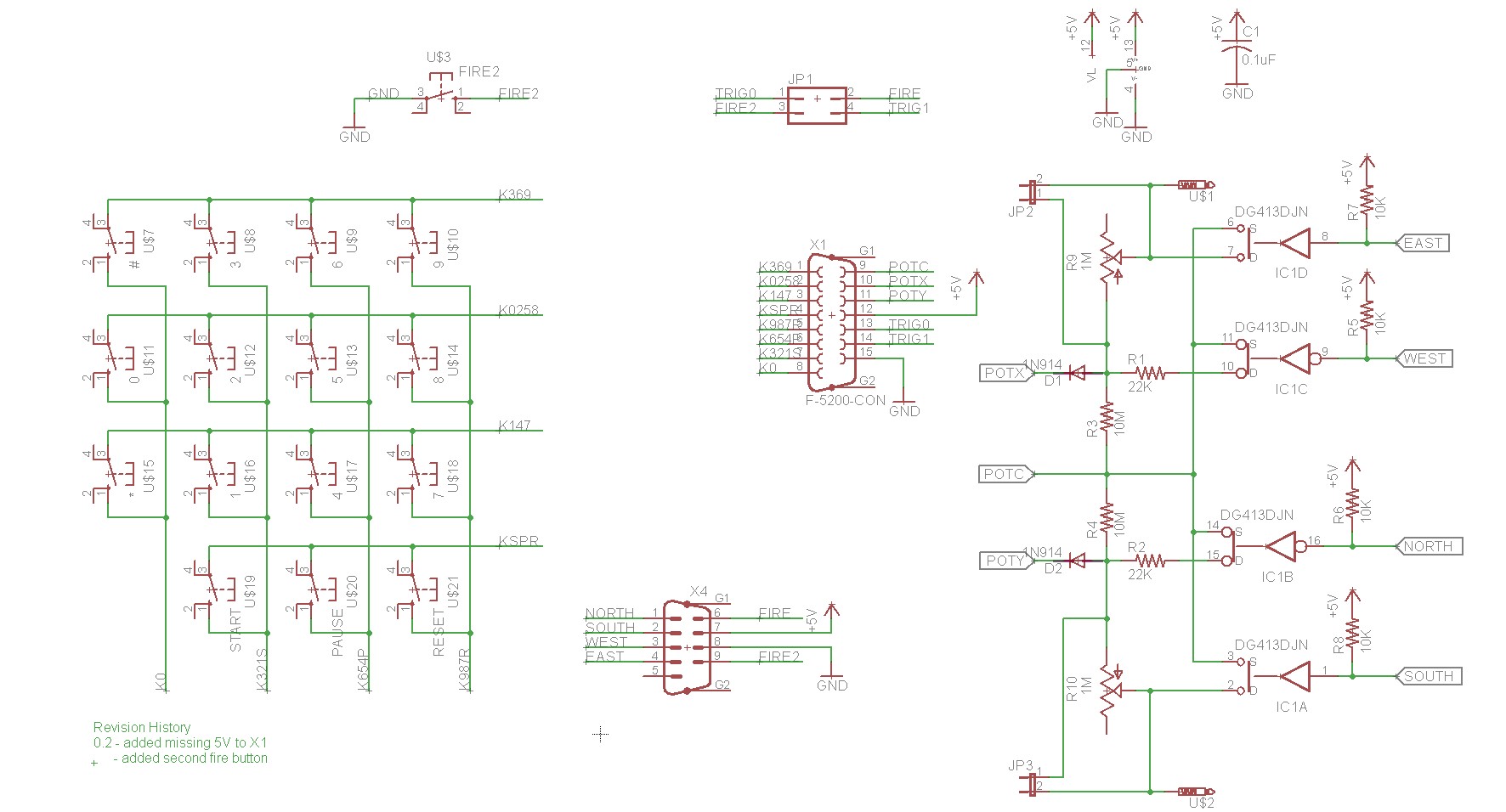
The design I used is based on a schematic on atariage from atariage user low_budget. I don’t know the full history, it’s possible that low_budget’s design can be traced back to earlier adapters such as the one in the official Atari 5200 FAQ. Here is the schematic:
The heart of the adapter is the DG413DJ chip. This chip is a quad analog switch, and it functions to insert various resistances into the 5200’s potentiometer loop. Note that two gates in the DG413DJ have inverted logic. This improves on the design of the 2600 adapter in the Atari 5200 FAQ, which required two ICs — a 4066 analog switch and a 4069 inverter.
Anyhow, moving along with how the circuit works… There’s a series of pullup resistors on the 2600 stick. When the stick is centered, all stick inputs will read 5V. When it’s moved in a particular direction, one of the inputs (East, West, North, or South) is grounded. If you move in a diagonal, you can ground two of the inputs at the same time, for example, East+South if you move the stick southeast.
When the stick is centered on an axis, a 1M potentiometer is applied across that particular axis. This potentiometer can be adjusted in order to ensure that digital center reads the same as analog center would. Adjustment is easily done with Pete’s test cartridge, or could probably be done with an analog game like missile command. When the stick is moved to the East or to the South, the 1M potentiometer is removed from the circuit, leaving a 10M resistor on the axis. When the stick is moved to the West or to the North, a 22K resistor is placed in circuit. These three resistors (1M pot, 10M resistor, 22K resistor) allow three specific set points that map the digital stick to resistance values that simulate the analog stick.
The 2×2 jumper block allows you to control the order of the fire buttons. Placing two jumpers horizontally is the way most people will want to do it. Placing them vertically will swap the two fire buttons.
There’s also a matrix keypad — it’s straight out of the Atari 5200 service manual.
Implementation
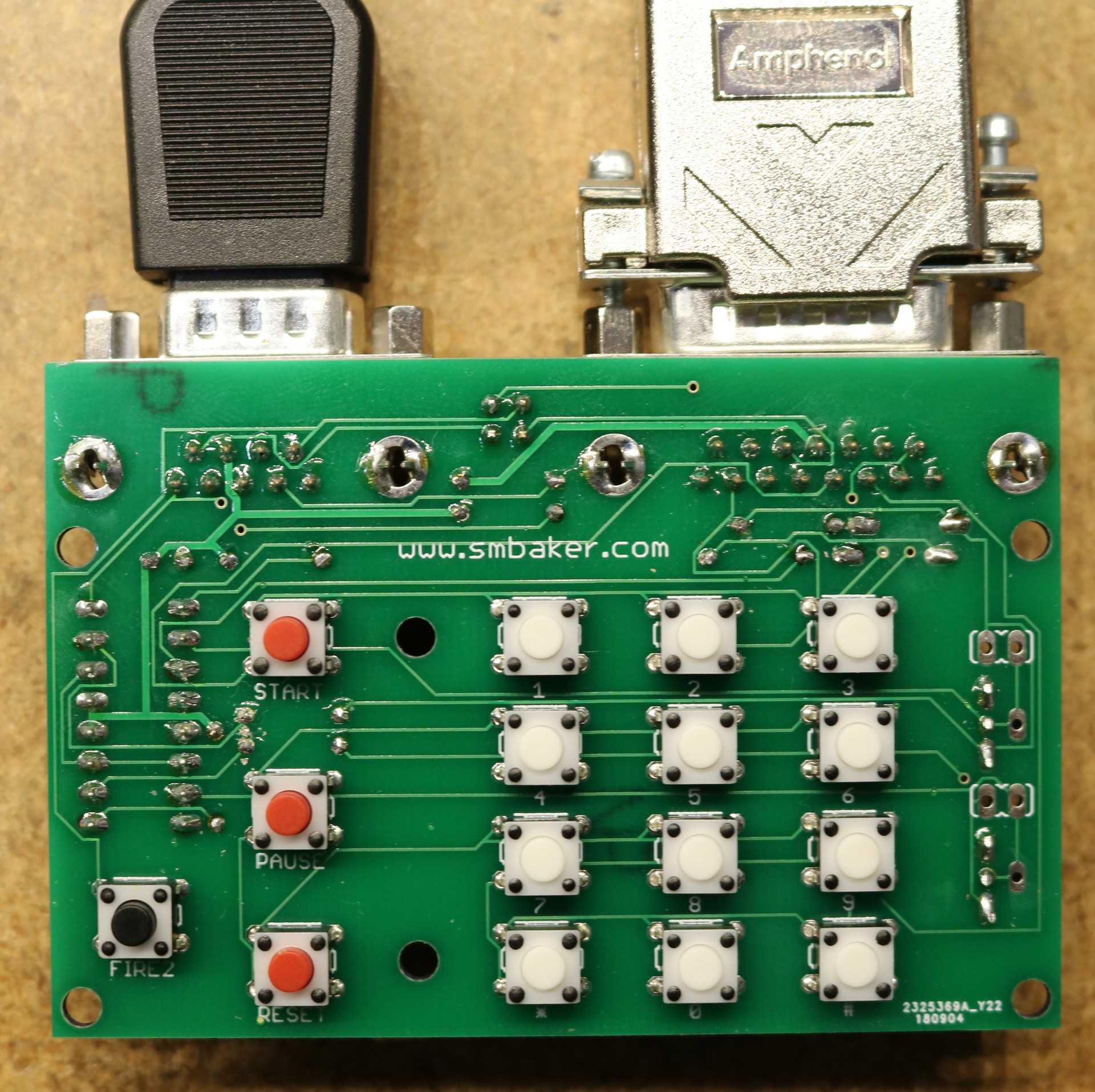
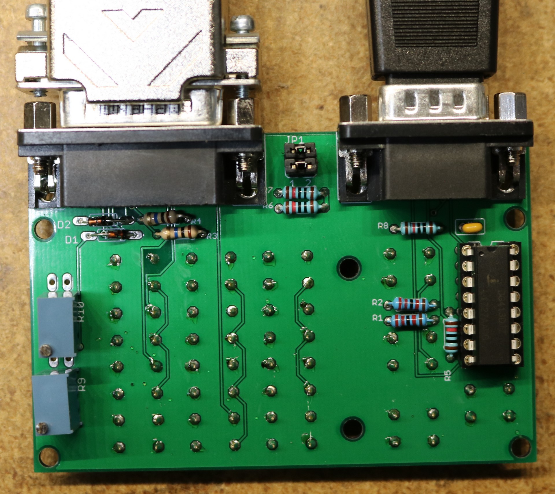
I had boards fabricated, here are a couple pictures:
As a departure from my typical projects, you can see that I placed buttons and components on opposite sides of the board. I figure this will make it easier to place the project in a custom case. You can see the two 10-turn potentiometers on the bottom — if a case is used, then some accomodation may be necessary to make it possible to reach those adjustments. The pots could be placed on the button-side of the board if desired.
Bill of Materials
| Part | Value | Quantity | Description | Source |
|---|---|---|---|---|
| C1 | 0.1uF | 1 | C-US025-025X050 | Digikey, 399-4264-ND (possible substitute 490-9145-3-ND) |
| D1,D2 | 1N914 or 1N4148 | 2 | Diode | |
| IC1 | DG413DJN | 1 | Quad analog switch | Digikey, DG413DJZ-ND |
| JP1,JP4 | 2 | 2×2 jumper, fire button selection | Digikey, S2012EC-20-ND (buy one, cut to size) | |
| JP2,JP3 | Optional headers for external pots | |||
| R1,R2 | 22K | 2 | Resistor, 22K | |
| R3,R4 | 10M | 2 | Resistor, 10M | |
| R5,R6,R7,R8 | 10K | 4 | Resistor, 10K | |
| R9,R10 | 1M | 2 | 25-turn trimmer, 1M | Digikey, 490-2877-ND |
| U$3 | 1 | Tactile switch, black (qty 1) | ||
| U$7-U$18 | 12 | Tactile switch, white (qty 12) | Digikey, 450-1649-ND | |
| U$19-U$21 | 3 | Tactile switch, red (qty 3) | Digikey, 450-1804-ND | |
| X1 | 1 | Female DB15, Right Angle | Digikey, AE10929-ND | |
| X4 | 1 | Male DB9, Right Angle | Digikey, AE10968-ND | |
| 1 | 16-pin IC Socket (optional; recommended) | Digikey, ED3016-ND | ||
| 4 | 0.100″shunt jumper | Digikey, S9337-ND | ||
| 1 | 15-pin joystick extension cable |
Board Ordering
I have a limited number of leftover boards on hand. I typically coordinate board sales over at the atariage forum as it allows others who are working on the project to communicate and help each other out. The current thread is at http://atariage.com/forums/topic/283926-yet-another-masterplay-clone/


Where do you have your pcbs made? Those look great.
Lately I’ve been having them made at JLCPCB.