In this post, I implement a compactflash adapter for the RC2014
If you haven’t read by first blog post on the RC2014, please start there as it will provide background information, including where I purchased the kit from.
Purpose
If I think back to my first computing experiences, there was usually some form of storage. In my case, I had a TRS-80 COCO, which I started with a cassette drive and then eventually evolved to a 5 1/4 floppy. For the Z80, it turns out that a CompactFlash card is surprisingly easy to interface. I used a couple of websites to help with this, including Grant Searle’s CPM Z80 computer and Retroleum’s 8-bit CompactFlash Interface.
Adding compactflash will allow us to expand the things we can do with the RC2014. With a bit of work it should be feasible to save and load data from a basic program. We can run the CP/M operating system.
Schematic and Design
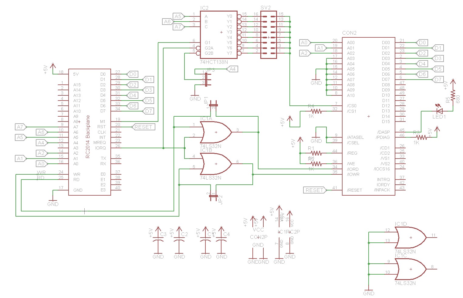
The schematic of my prototype is shown below:
As you can see, we have the typical 74HCT138N for address decoding. This allows us to put the CompactFlash card on any of eight addresses: 00, 20, 40, 60, 80, A0, C0, or E0. In my example code, I have placed it at E0. There’s a Jumper, JP3, that can be used to connect A4 to one of the active-low inputs of the 74HCT138. This allows you to set the 74HCT138 be active for only 10h of address space instead of 20h of address space like my other boards. There’s really no good reason not to jumper it that way.
The 74HCT138’s output is tied to the /CS0 pin of the compact flash card, and is used as chip select for the primary bank of compactflash card registers. The compactflash also has a secondary bank, selectable by /CS1. We don’t need those, so /CS1 is tied to +5V. Either data pins are connected from the Z80 to the CF dard, D0-D8. There are three address lines, A0-A2. This allows us to select any of eight registers on the compactflash card, which are all the registers we need to implement the 8-bit interface. There are read and write pins, /IORD and /IOWR that are connected to an OR gate that combines the Z80’s IOREQ signal with the Z80’s RD and WR signals. There’s a /RESET pin, which we hook up to the same reset line that drives the rest of the RC2014.
IC1 is a quad OR gate that combines IOREQ and RD to form IORD and combines IOREQ and WR to form IOWR. Since IOREQ, RD, and RW are active low, ORing IOREQ and RD is an effective way to generate an active low signal that is only low if both IOREQ and RD are both low. Two gates of IC1 are unused and their inputs are grounded.
There are also a number of pins that I tied to ground. A03-A10 are addressing pins that we don’t need for 8-bit mode. /ATASEL forces the compactflash into True ATA mode. /CSEL has something to do with master/slave cable-select. /REG and /WE aren’t used in True IDE mode and are pulled to 5V. /PDIAG is the pass-diagnostic signal. I’m not sure exactly what that’s for, other than it’s something to do with master/slave mode and we’ve pulled it to 5V.
/DASP can be used to implementing a busy LED that will show you when the drive is busy. This also seems to serve some kind of purpose in the master/slave protocol.
The rest of the pins are left floating.
Hardware Implementation
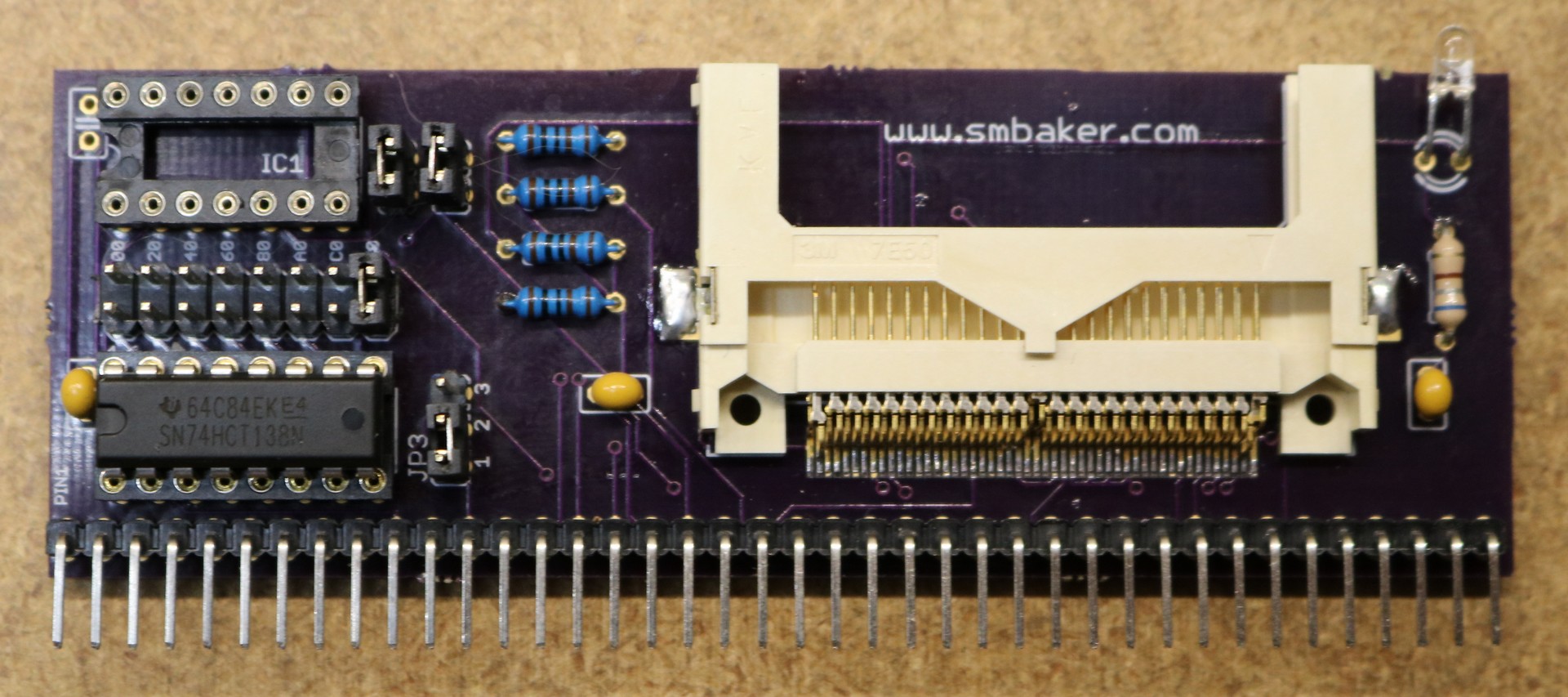
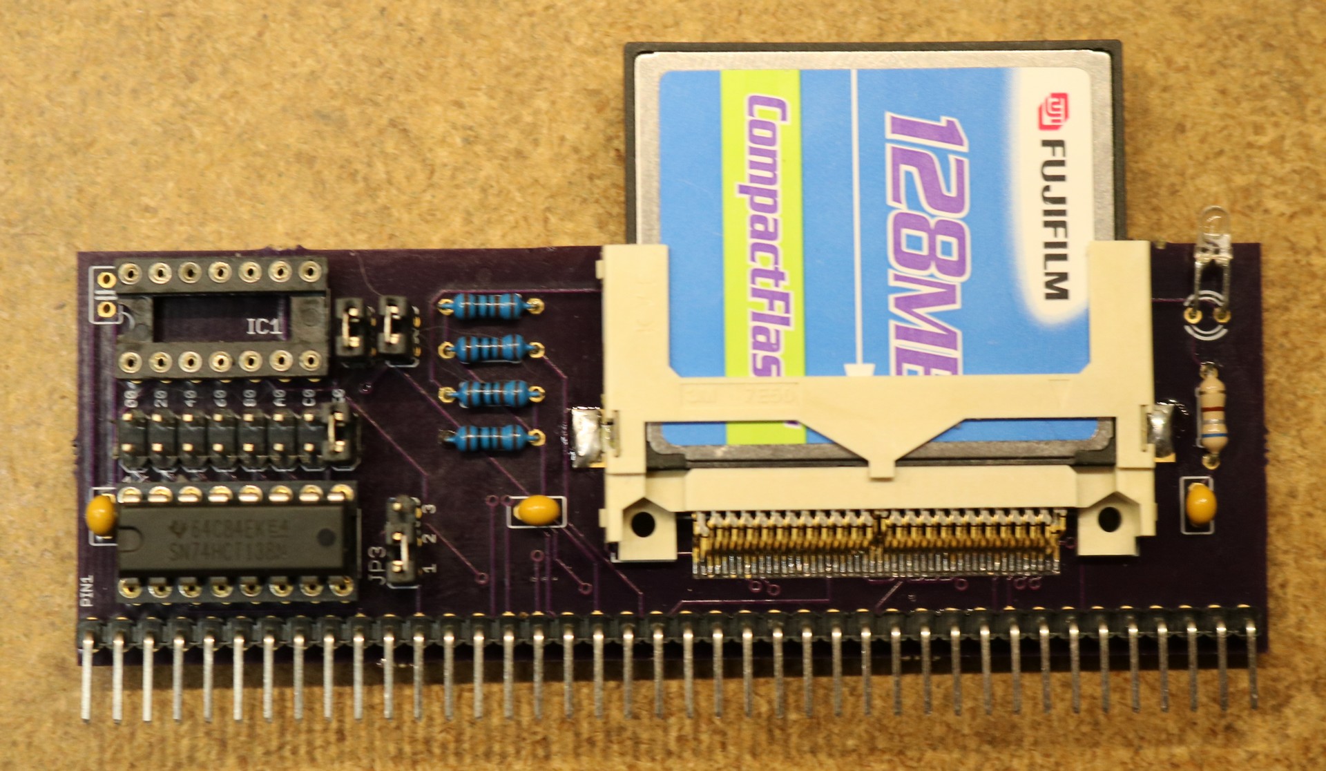
A picture of my prototype is shown below:
I thought I was going to be clever, and omit the OR gate (IC1 in the schematic) that generated IORD and IOWR signals by combining RD/IOREQ and WR/IOREQ. I added some jumpers that supplied RD and WR instead. In fact, I originally wrote up this blog post thinking that approach was working and IC1 could safely be left out. Turns out I was wrong, and CP/M became unstable when reading large files. I haven’t had time to research why yet, and I’m guess it’s either some quirk of timing or some quirk of signal quality. Until I figure out why, you should assume that IC1 needs to be populated, and the two jumpers to the right of IC1 removed.
The CompactFlash socket itself is a surface mount part, digikey part number 3M155880-ND. They are about eight bucks each, and I’d suggest ordering a spare just in case there are any mishaps while soldering it. The pins are spaced relatively closely together, so it can be a bit of a beast for someone who is not familiar with SMD work. I used my Aoyue 861A++ rework station to do the soldering. I started by laying down a continuous bead of solder paste, then used the hot air iron on it, then used desoldering braid to clean up any bridges. There are lots of techniques for soldering SMD devices, some even using a traditional iron (drag soldering). You might want to practice on something else before working on the relatively expensive (about 8 bucks) and delicate compactflash socket. After soldering inspect with a microscope or magnifier to make sure there are no bridges.
Compatible CompactFlash Cards
I obtained a number of CF cards from eBay. I concentrated mainly on getting 128 MB and 64 MB cards, as those are the maximum and minimum usable by Grant Searle’s CPM prototype. Successful cards included Fuji 128MB, PQI 128MB, Wintec 128MB, Cisco 64MB (these Cisco cards seem really plentiful on eBay), and Mr. Flash 128MB.
A Viking 128MB card behaved oddly. It took this card approximately 30 seconds to become not-Busy after power-cycle. I believe this has to do with some issue with the master/slave protocol and that it was timing out waiting for the slave. Probably something to do with the /DASP or /PDIAG pins. The busy LED also didn’t work properly, staying on the whole time. If you encounter a Flash card that seems to misbehave, try giving it a good 30 seconds to see if it’s this same issue.
I also had a Sandist 64MB card what was either outright defective, or that I managed to damage. I can’t get it to work in either the RC2014 or my windows PC.
Programming
Using the compactflash card is relatively straightforward. The retroluem site linked above explains some of this a little more clearly than I do, and documents how to read the Disk ID, which can be a useful way to verify the card is working.
Keep in mind that when I say “register x” that’s relative to the port address that you’ve selected for the compactflash card. If you put it as 0xE0 like I did in my examples, then register 0 is as 0xE0, register 1 is at 0xE1, …, register 7 is at ox E7.
Setup:
- read register 7 until the busy bit (0x80) is unset
- write 1 to register 1
- write 0xEF to register 7
- write 0x82 to register 1
- write 0xEF to register 7
0xEF is the “set feature” command. Feature 1 enables 8-bit mode. Feature 0x82 disables any write caching. You should do this whenever the compactflash is reset or power cycled.
Read a sector
- read register 7 until the busy bit (0x80) is unset and the ready bit (0x40) is set
- write 1 to register 2, to set the sector count to one sector
- write bits 0..7 of the block address to register 3
- write bits 8..15 of the block address to register 4
- write bits 16..23 of the block address to register 5
- take bits 24..27 of the block address, or them with 0xE0, and write to register 6
- write 0x20 to register 7. This is the “read sectors” command.
- read port I7 until the busy bit (0x80) is unset and the DRQ bit (0x08) is set
- read 512 bytes from register 0
Write a sector
- read register 7 until the busy bit (0x80) is unset and the ready bit (0x40) is set
- write 1 to register 2, to set the sector count to one sector
- write bits 0..7 of the block address to register 3
- write bits 8..15 of the block address to register 4
- write bits 16..23 of the block address to register 5
- take bits 24..27 of the block address, or them with 0xE0, and write to register 6
- write 0x30 to register 7. This is the “read sectors” command.
- read port I7 until the busy bit (0x80) is unset and the DRQ bit (0x08) is set
- write 512 bytes to register 0
I originally implemented this entirely in basic (see cf.bas in my github repo). Reads worked fine, but the writes did not work. I think what happened was that I was writing to the card too slowly, and the write operation was timing out. RC2014 basic is a very slow way to try to do peripheral IO. Assembly is much, much faster.
My second implementation was to modify the basic ROM to include three new statements: DINIT, DREAD, and DWRITE which handle initialization, read, and write. The read and write transfer the contents of a sector to a buffer in RAM, which can then be peeked and poked by the relatively slow basic interpreter. This is demonstrated by cf_dbas.bas in my github repo. Extensive modifications to the Basic ROM were necessary, and I will make patches available in the github repo, so that you can assemble your own basic ROM should you wish to do so.
Source Code
You can find source code in my github repo at https://github.com/sbelectronics/rc2014.
- basic/cf.bas — this is the compactflash code written entirely in basic. It worked for reading and disk ID, but I could not get it to work with writes.
- basic/cf_dbas.bas — this is a basic program that uses a modified basic interpreter that support the DINIT, DREAD, and DWRITE commands. Compactflash operations are done in assembly to a buffer in memory, and are peeked and poked by the basic program.
Bill of Materials
- pcboard, Osh-Park
- 40-pin right angle 0.100″ male header
- 2×8 pin male header
- 74HCT138N
- 74HCT32N
- Compact Flash Socket, digikey 3M155880-ND
- (4) 1k resistor
- 680 ohm resistor
- (4) 0.1uF capacitor
- LED
- IC sockets as desired
PC-Board ordering
As usual, the pc-boards are available on Osh Park. I do not sell them myself, and do not make any money from Osh Park’s sales. You do have to order them in Qty 3.


Hi Steve,
Been having big problems with this card. Every time I inserted the card into the slot the computer froze and would not reset. Worried about shorted pins and removed and replaced the CF Card socket ( hot air guns are really useful here!) but to no avail. Then the penny dropped. Your socket is a reverse of the ones I got here in the UK. When you insert a CF card in my sockets the bottom of the card is visible, whereas in yours the front is visible. I purchased a CF ATA adaptor from ebay and it has the same layout as yours from Digikey. Problem with getting the part from Digikey is that the shipment cost almost doubles the cost of the parts. So I’m making a home brew board using the ebay adaptor whilst searching for a compatible CF card socket in the UK. Here is link to the photo that shows the differences
https://1drv.ms/i/s!Aq1zNf6ZNlFIwyVPT31r_hP3bR5K
best Regards
Paul
Hi Scott,
My apologies for getting your name wrong! More haste less speed.
Best Regards
Paul
Hello,
can this card be used as a normal floppy drive for a cp/m System? I dont want to write Assembler for the Z80, only use CP/M as it is without deaper knowledge how the data is stored in the flash card.
Regards,
Christian