This write-up is on a Viper 350 Plus that I install last week. The goal of this system was to have power door locks and keyless entry, but I found that buying a complete alarm system cost little more than buying just a keyless entry system. Personally I don’t give a hoot about the alarm itself, but it does offer the flexibility of adding additional sensors in the future that might make it more useful (like proximity or motion), especially in a jeep.
So far I have the alarm and relays wired. One door actuator is done and waiting for a break in the weather before finishing the job. It took about two half-days on the weekend to do the alarm install. Much of the time was due to looking over the jeep, figuring out where to mount everything, figuring out where the wires were that needed to be tapped, etc. "Measure twice cut once" as they say.
0) Parts
My Viper came from a shop on amazon marketplace. It cost $80. Best Buy sells the same alarm installed for about $250, so that’s a savings of about $170 if you do the work yourself. Beware that Viper alarms are only waranteed if installed by a registered dealer. There’s also a 2-way system very similar to this one called the "Responder 350" if you’d prefer a 2-way alarm. Costs about twice as much.
For door lock actuators I found some DEI 524N actuators on ebay. They are high-torque actuators that are nice and compact. A bit pricier than the no-name brand ones though. Paid about $20 (w/ shipping) each for them. Best Buy cost for installed door lock actuators is $80 per door.
You’ll also need a pair of door lock relays. They’re the usual automotive 5-pin relays. You can also get pre-wired modules that contain two relays internally, and you can get kits (from ebay) that include a couple of relays with pre-wired sockets.
1) Mounting the control box
I decided to place the control box (aka "alarm brain") behind the driver’s side knee panel, beneath the steering wheel, on top of the black air duct that runs across. Next to the control box is where I located the starter disable relay.
2) Power
The alarm needs B+ constant power and we had a few options for this including grabbing it from the ignition switch, running a separate fused wire from the battery, or finding an existing circuit. Ultimately I opted for the third option and looked for unused circuits on the fuse panel behind the glove box. The best I could come up with was the subwoofer fuse. Measuring amperage on the subwoofer with volume turned up to high (much louder than I personally would ever listen to) showed the circuit using only about two to three amps. It’s protected by a 20-amp fuse. I figure this is enough capacity to power the alarm and the door lock solenoids. I spliced the wire (black/red) behind the fuse panel and ran it over to the drivers side.
3) Ignition and Start
The alarm includes a starter disable relay that interrupts the starter signal. The alarm supplies ground to the starter disable whenever the alarm is armed. +V to the starter disable relay comes from the ignition switch. Thus, if you turn on the ignition switch while the alarm is armed, the starter disable relay engages, disconnecting the starter signal. It’s a failsafe system in that if the alarm box fails (or the alarm fuse is blown) the relay is never engaged and you’ll be able to start your vehicle.
Wiring this involves finding two wires in the ignition switch harness: Start and Ignition/Run. Start is Pink/Orange and ignition/run is Pink/LightGreen. I found it easiest to splice into this connection by un-plugging the ignition switch and temporarily pulling the wire over to the passenger side of of the steering column where you can gain better access to it.
4) Ground
There are a couple of good existing grounds visible when you have the driver side knee panel removed.
5) Siren
Mounted the siren under the hood near where the cruise control servo is located. Fed both power and ground to the siren back through the firewall bulkhead to the alarm control box.
6) Door pin switches
The pin switches in the left and right doors are not connected in common; they are individual signals that feed into the instrument panel — thus you can’t splice into both pin switches at the same time. This leaves two options — you can use diodes to isolate the two pin switches, or you can use the signal that operates the dome lights and courtesy lights. I opted for the latter. The courtesy light is easily located below the driver’s knee panel. Remove one screw and the light will drop down with ample wire exposed to work with. You want the Yellow/Orange wire. This signal is active negative (-), so use the (-) trigger to the alarm box.
7) Parking lamp flash
The park lights are operated by the White/Yellow wire which starts at the multi-way switch where it goes to a number of places — to the instrument panel via connector C300, to the engine compartment harness through C301 (where it goes to the front park lights), and to the rear of the vehicle by way of a wire harness passing along the dirvers side of the vehicle. Just look around the large wire looms in the knee panel area until you find it, it shouldn’t be too hard to find.
8) Dome light supervision
I opted not to bother with this because it required yet another relay.
9) Antenna / "command center"
Newer viper alarms have the valet switch and LED integrated into the little box with the antenna which they name the "command center". Viper recommends mounting it on the top of the front windshield, right above the rear view mirror. That’s exactly where I located mine, running the wire down through the trim around the driver’s side of the windshield, behind the dash, and down to the box.
Note – The 350 plus includes a feature where you can disable the alarm by turning on the ignition and pushing the valet switch. Mounting the valet switch in the antenna makes it obvious to any professional thief where this switch is… I figure the purpose of the alarm is to keep the "mostly honest" people honest, and it’s not going to do much to deter a determined professional crook, so I’m not going to bother with relocating the switch. If you’re worried about it, then options include wiring a hidden switch, or connecting the switch input to an existing switch in the vehicle, like a brake switch or clutch switch.
10) Door Lock Relays
For aftermarket locks you need a pair of door lock relays. You’ll need to find B+ and GND to power these relays. I grabbed B+ from the subwoofer fuse, the same source as my B+ for the alarm itself. I did run a separate wire to supply this B+ from the fuse however, so as not to induce large loads or spikes into the B+ that powers alarm. If I’d have had a larger wire on hand I’d probably have used a common wire to run them both, but I figured I’d err on the safe side; don’t need the alarm glitching every time a door lock solenoid engages.
Measured the door lock solenoids out at approximately 3.5 amps each. Three of them (two side doors plus tailgate) should amount to 10.5 amps, fitting comfortably on the 20 amp circuit that I’m using. Not even sure if/when I’ll get to wiring the tailgate. If power does become an issue, then I can always rewire and power the relays/solenoids from a fused line off the battery.
As far as wiring the relays themselves, there’s a number of documents on the web. The best one is tech tip #1041 from DEI, but it’s available only to dealers (hint: see bittorrent for a collection of DEI manuals and tech tips).
11) Door lock solenoids
The door actuators that I used are DEI 524N, which are a nice compact solenoid.
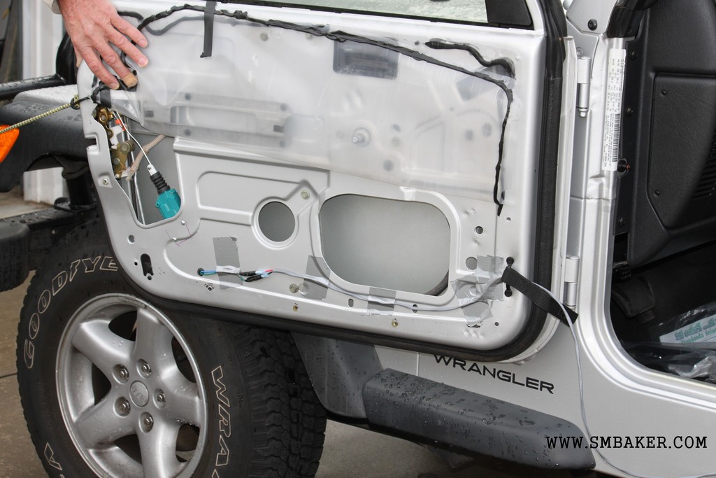
Start by removal of the inner door panel by using a window handle removal tool (check your autoparts store) to get the window crank off. Remove the two screws on the grab handle, and the three screws around the bottom and back of the door. If memory serves, all 5 of these screws use a torx bit (T15, I think). At this point the inner panel is held by a bunch of plastic clips. The auto-parts store may have a panel removal tool that might help you here, it looks like a bent screwdriver with the forked end. As careful as you are a clip or two may bend or break. Once the inner panel is off, fold up the plastic sheet that is held on by some black sticky glue.
Now, familiarize yourself with the way the door lock works by locking and unlocking the door. You’ll see the little rods in the lock mechanism moving. Basically, you want to install your actuator so that it pushes and pulls in the same direction that the door lock rod moves.
I’ve attached a couple of pictures that show how I mounted the solenoid. I was able to mount it using just the two rear-most screws on the solenoid which felt pretty secure. To drill the mounting holes, I simply held the solenoid in position on the door, drilled a couple of pilot holes, enlarged the holes, and then mounted the solenoid inside.
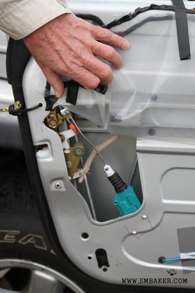
I used a rubber grommet to feed the solenoid wires through the door metal, spiced it with a couple of butt connectors and then routed the wire out of the door panel through the opening where the strap is.
Before you close up the door, make sure to check that the windows roll up and down without hitting anything (I had plenty of clearance with these compact actuators) and test the operation of the solenoid by applying power to make sure it locks and unlocks properly.
All things considered, the door actuators seem to be the easiest part of the job… Plenty of room to work with.