In this post, I restore a Burroughs B21 Vintage Computer
Background
The Burroughs B21 was one of the computers that I used as a teenager. It was a long, long time ago. My Dad had brought the machine home from work for me to “play” with as they weren’t actively using it. This would have been around the time when I had a TRS-80 Coco of my own. I’m not sure if it was before or after I got my first PC compatible, a Tandy 1000. The B21 runs an unusual operating system called BTOS that I remember fondly. This is the same motivation that led me to investigate the Convergent NGEN computers a few years back, which were a little easier to source on eBay.
The Burroughs B21 is a rebranded version of the Convergent AWS, and while AWS do occasionally show up on eBay, it is very rare. Aside from the sheer age of the computers, it’s also the case that they’re bulky and difficult to ship. I think the scrappers take one look at these things and decide to cut them down for scrap. Myself and other members of the Forgotten Machines community have gone to great lengths to save the occasional convergent machine in the past and this one was finally my chance when it came up on eBay:
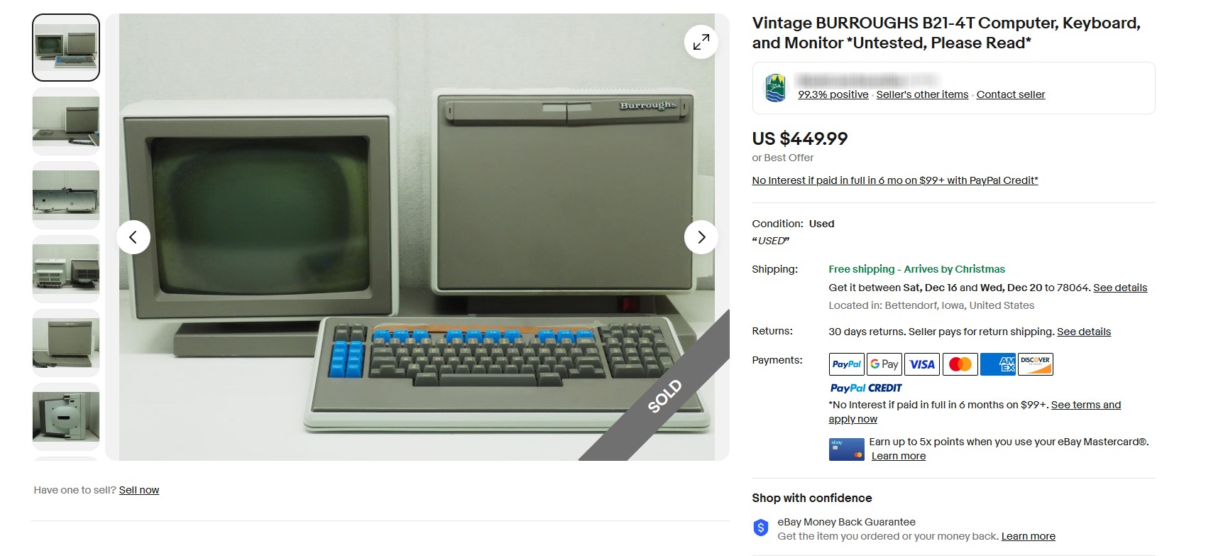
The description read as follows:
Please Read: Computer, Monitor and Keyboard are all untested. Cable to monitor has been cut, and it has some kind of mineral buildup inside the screen itself. Screw or bolt that attaches monitor to stand is missing. Some rust colored liquid has also leaked out of the monitor. Sold as-is.
That’s all a bit alarming, especially the descrption of the “mineral buildup inside the screen” and the “rust colored liquid”. The monitor defect is well known as “CRT Cataract”, but the rust-colored liquid was something I hadn’t heard about. Why was the cable cut? Was it cut because the tube was damaged beyond repair?
It had free shipping, which is considerable given the size of this machine. So I bought this computer, and back in December 2023 it showed up on the UPS Truck to my doorstep. It would sit around my home for almost two years. Although this one of my dream machine purchases, fixing the monitor was something I would continue to procrastinate.
Problem #1 – Cut Monitor Cable
The AWS is an integrated computer system, with the computer and the monitor being part of one large assembly. The cabling is internal and runs through the pedestal from the computer to the monitor. I knew it had been cut from the description in the listing. I opened up the monitor and had a look:
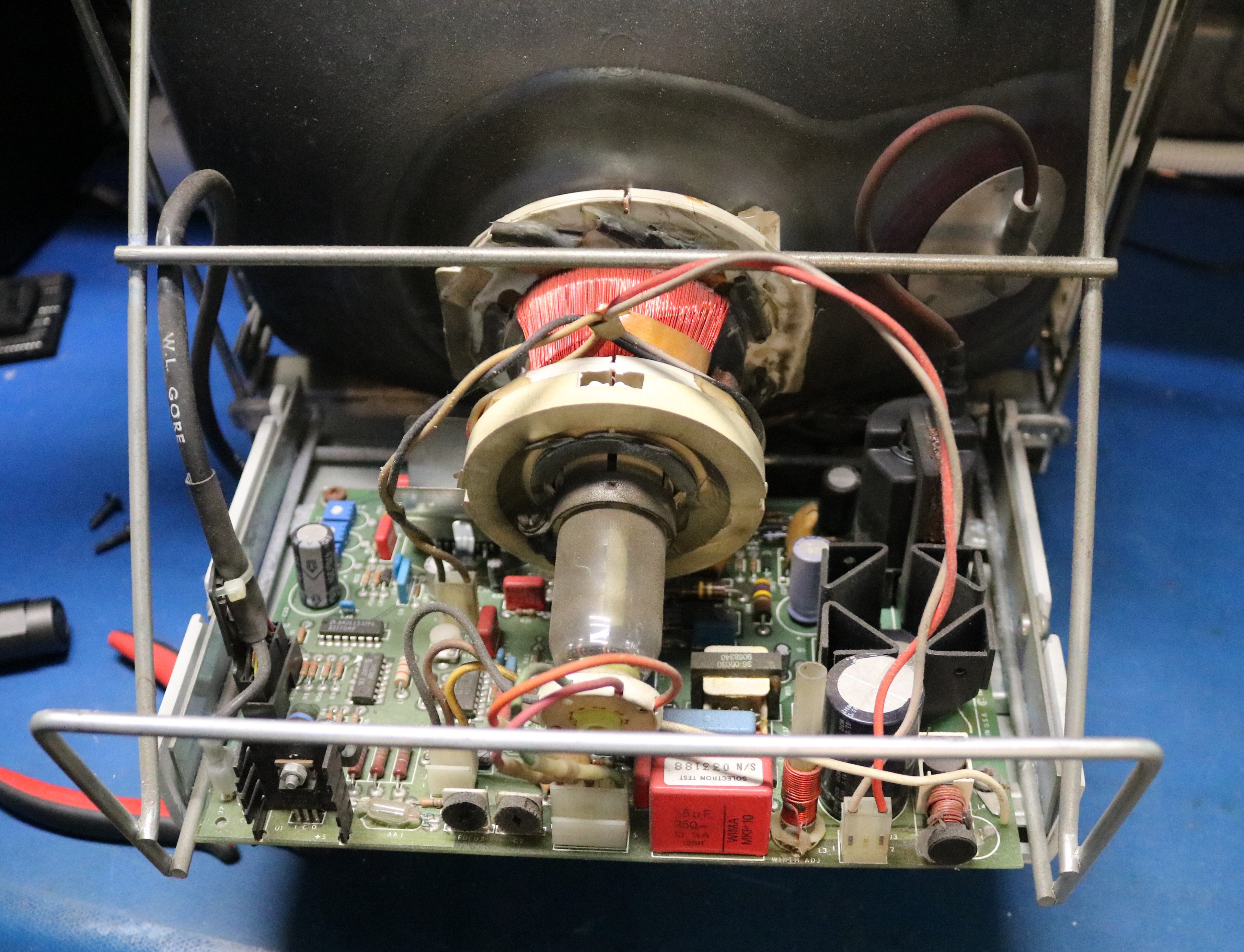
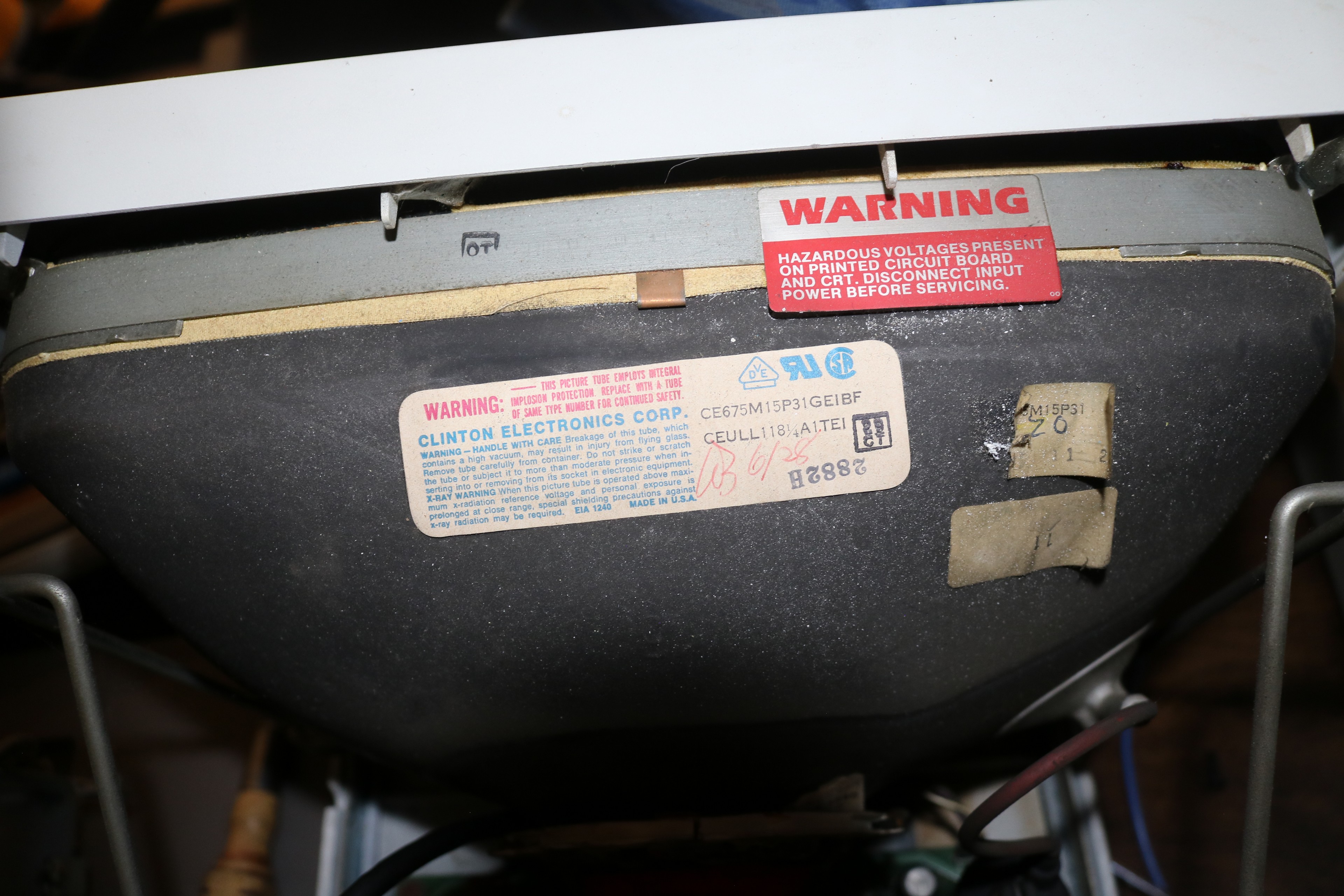
You can see the cutoff cable on the left; it’s the one marked “W.L. Gore”. It’s cut right at the monitor base. There’s no apparent damage to the tube, which is made by Clinton Electronics:
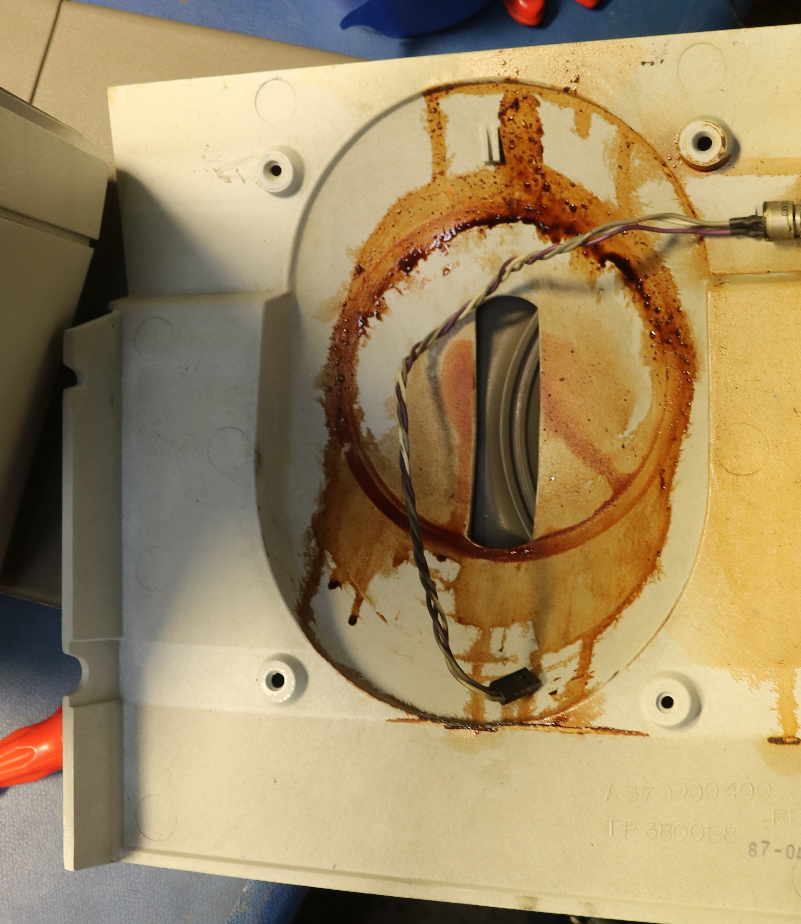
There was considerable “brown goo” in the bottom of the monitor case:
The cable repair was straightforward though tedious. The cable contained four single conductors as well as four shielded twisted pairs. That made for twelve wires and four shields to repair, plus an outer coaxial braid:
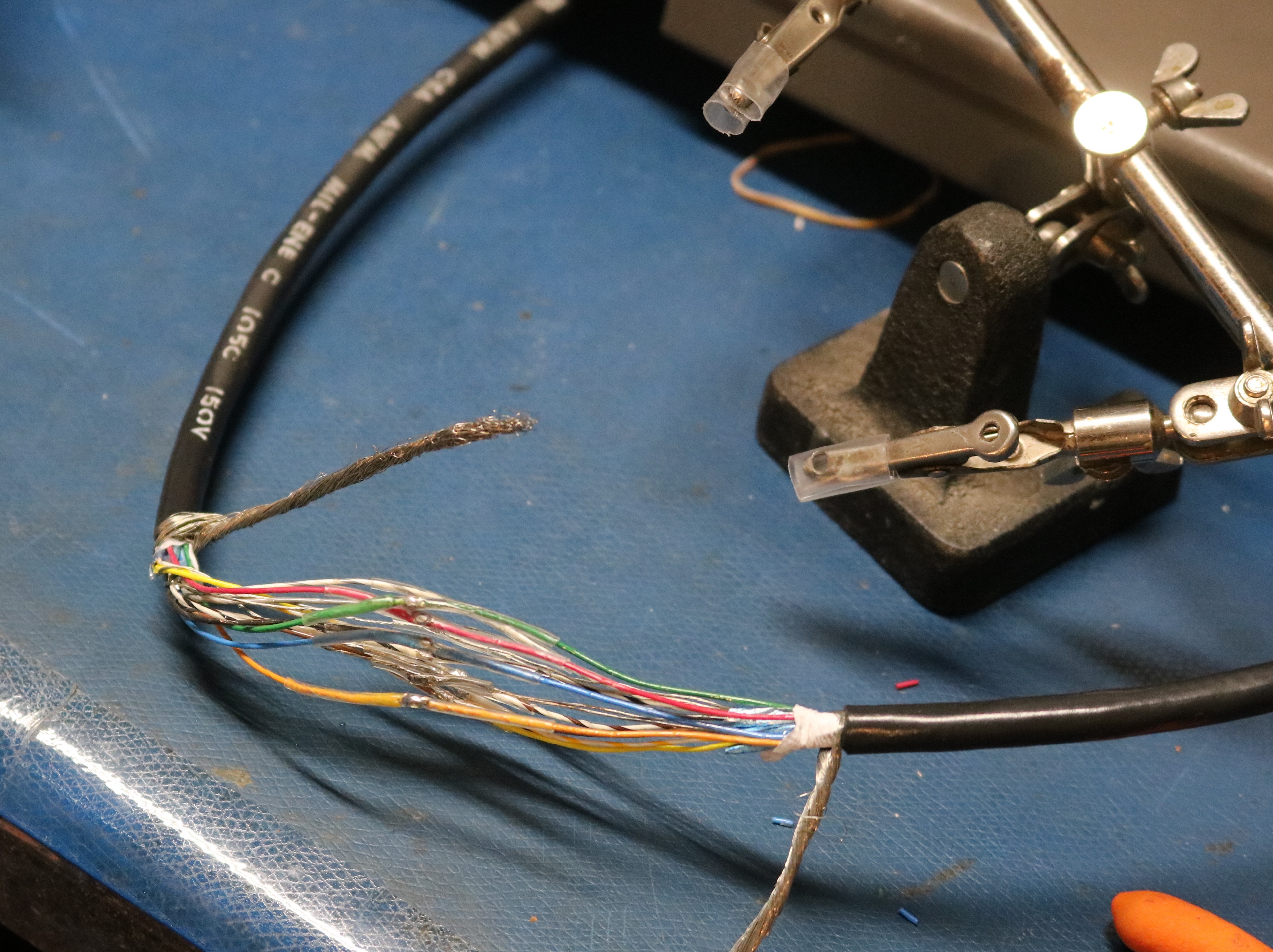
After this, I wrapped it in tape, connected the outer shield, and ran it up through the monitor base:
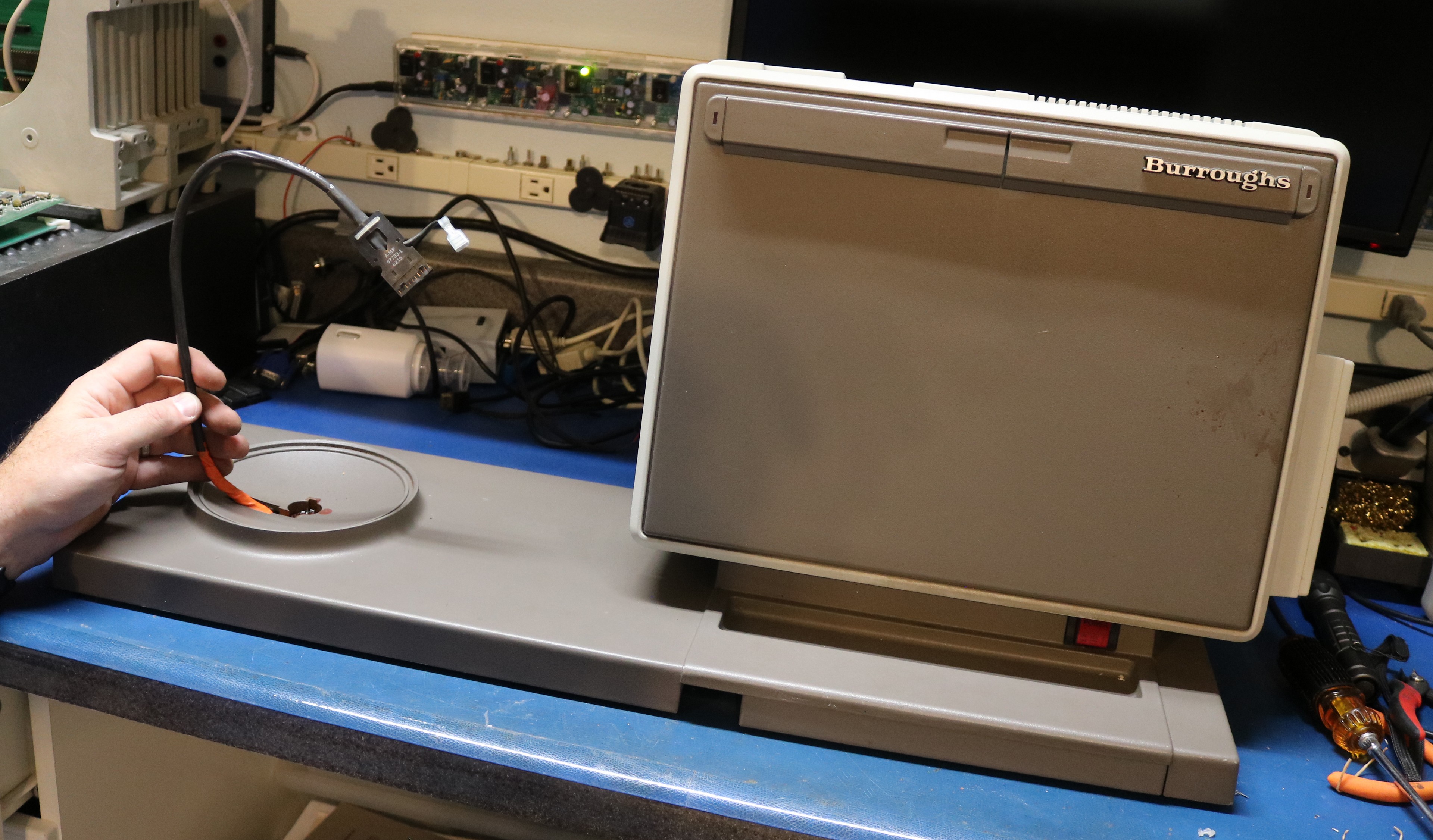
Physically reattaching the monitor was straightforward — it was just a 1/4-20 bolt and a washer. With the monitor replaced, I was able to power up the machine for the very first time:
Problem #2: That Horrible Ear-Piercing Tone
When I powered on the computer, I was immediately greeted with the steady high-pitched tone out of the computer’s speaker. There was no video. There was no HDD or FDD access. Just a noise that makes you want to leave the room that will not stop until the power is cut. When turning the machine off and back on I would get a different tone, but it was always solid and continuous. The reset button would cause the tone to stop while it was depressed and then the tone would immediately resume when the button was released.
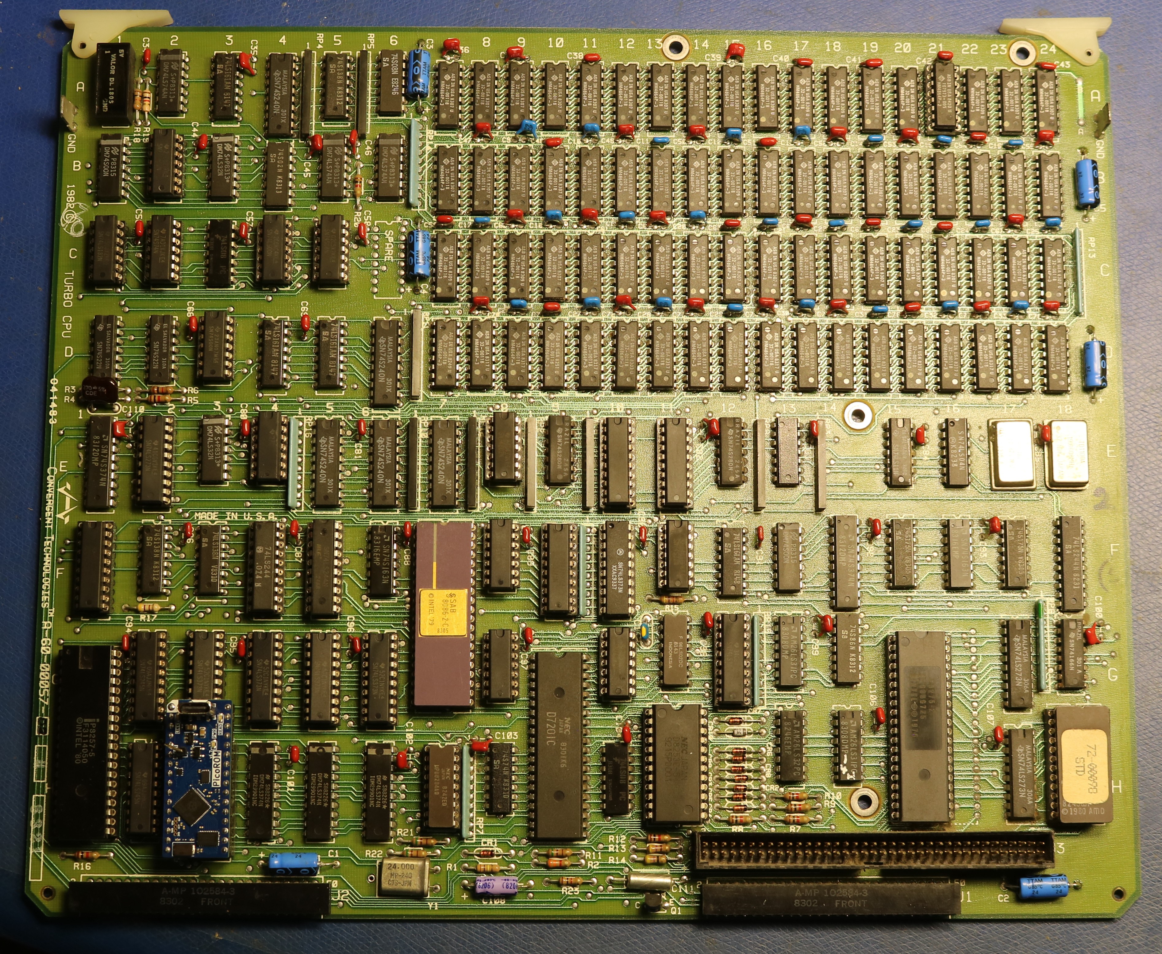
The very first thing I did was to check the power, to verify that +5V and +12V was steady. Computers will generally malfunction if their power is inconsistent, as often happens when old electrolytic capacitors fail in the power supply. Putting my DMM on the power rails showed the power was good. So much for the easy low-hanging fruit. Next I pulled the CPU board:
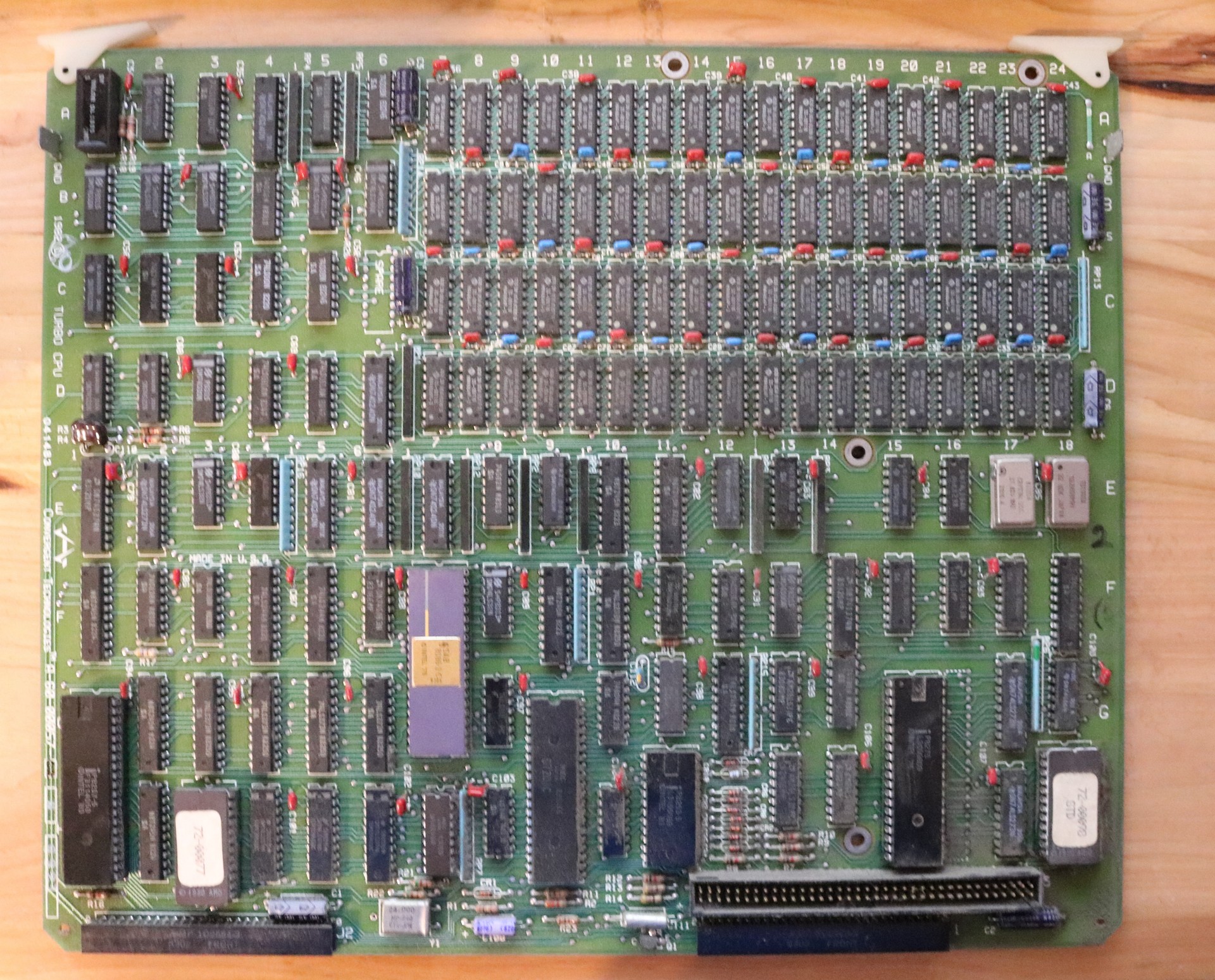
It’s not the world’s best picture — the focus I think is good, but there’s a lot of dust on it. Above we can see the CPU. The significant chips, from bottom-left to bottom-right:
- Intel 8257 – DMA controller
- AMD 2732 ROM containing bootstrap loader
- Intel 8086 – CPU
- NEC D7201C – serial interface
- Intel 8253 – counter/timer
- Intel 8275 – video controller
- AMD 2732 ROM containing CRT font
At the top right there is an array of DRAM that is all HM4864P-3.
I checked a few obvious things, such as whether clocks are arriving to the 8086 and whether there are memory reads. I reseated all socketed ICs, and tried replacing the 8284 clock generator (little IC below the CPU) just in case. None of that did any good.
I pulled the bootstrap ROM and looked at the code:
ff000: fa                 cli                           ; called from ROM entrypoint
ff001: e4 f4              in      al,0F4h               ; disable parity check
ff003: 33 c0              xor     ax,ax
ff005: 8c c3              mov     bx,es
ff007: 81 e3 03 00        and     bx,3h
ff00b: 74 04              je      0FF011h
ff00d: 8a e3              mov     ah,bl
ff00f: 8a c2              mov     al,dl
ff011: 8e d0              mov     ss,ax
ff013: 33 d2              xor     dx,dx
ff015: b0 36              mov     al,36h                ; program speaker counter, write 36h to port 46h. Sound off.
ff017: e6 46              out     46h,al
ff019: bd 1f 00           mov     bp,1Fh
ff01c: e9 d0 0d           jmp     0FFDEFh               ; does stuff with timer interrupt
ff01f: bd 25 00           mov     bp,25h
ff022: e9 ff 03           jmp     0FF424h               ; setup the CRT ?
ff025: bd 2b 00           mov     bp,2Bh
ff028: e9 33 04           jmp     0FF45Eh               ; setup the 7201 ?
ff02b: bd 31 00           mov     bp,31h
ff02e: e9 82 04           jmp     0FF4B3h               ; checksum ?
ff031: bc 37 00           mov     sp,37h
ff034: e9 f1 04           jmp     0FF528h               ; clear display buffer and memory test?
ff037: bd 3d 00           mov     bp,3Dh
ff03a: e9 27 02           jmp     0FF264h
ff03d: bd 43 00           mov     bp,43h
ff040: e9 c4 04           jmp     0FF507h               ; turn on display
ffff0: ea 00 00 00 ff     jmp     0FF00h:0h             ; entry point on reset
The annotations are mine, upon disassembling the ROM. The 8086 starts at address 0xFFFF0, where the ROM immediately jumps to 0xFF000. After this, it disables parity check, sets the stack segment, and then turns off the speaker.
The speaker is driven, by way of a transistor, from the 8253 counter/timer chip. According to the 8253 datasheet,
Prior to initialization, the MODE, count, and output of all counters is undefined.
So my working theory was that the code at 0xFF0015 that initializes the counter was not working. The IN instructions at 0xFFF01 is an easy one to check, since it’s the third instruction executed and performs an IO operation. I put the scope on the board, powered up the computer, and verified that there were no IO operations coming from the 8086. If there was no IO, then it wasn’t making it to that instruction, which meant it either wasn’t executing all, or was executing random gibberish.
At this point I made a priority list of all the ICs that were in the path between the CPU and ROM. Most of these were bus transceivers, such as 74LS373 or 74LS245. But there was also a surprising amount of logic. The 8086 has a 16-bit data bus, and Convergent interfaced it to an 8-bit ROM. There is logic that splits a 16-bit operation into two 8-bit operations and combines the result. All that logic had to be considered as potentially defective as well. Of course, nearly all of these ICs were soldered, so I had to desolder, test, and socket each IC that I wanted to check. It was a long and tedious process that I worked on between Christmas and New Years.
The main problem turned out to not be any of the ICs I suspected, but was the 8253 timer chip, which was loading down the data bus making it reliable. I have to thank ashlin over at Forgotten Machines who had suggested checking this. I’ve actually run into this same problem before on an Epson QX-10. An IC such as an 8253 or 8259 that is attached to the data bus can fail in such a way that it leaves its data bus outputs active. Then when the CPU goes to fetch an instruction from ROM, we have two devices using the data bus at the same time, and the data bus is garbled. This seems like a not uncommon failure mode for these peripheral ICs.
After replacing the 8253, the obnoxious noise stopped.
Problem #3: Other Bad ICs: Developing a custom Diagnostic ROM and replacing more ICs
While testing the ICs, I created my own diagnostic ROM. Initially I wanted code that did only one thing — to turn off the damn speaker, and verify that I could talk to the 8253. I then expanded it to do all of the following:
- Emit two beep tones at different frequencies. This verifies the CPU and 8253 are working.
- Blink LEDs on the keyboard. This verifies the 7210 serial interface to the keyboard is working.
- Test all the RAM and emit a beep code indicating which bank and bit was bad.
- Initialize the 8275 display controller.
- Move the cursor to the center of the screen.
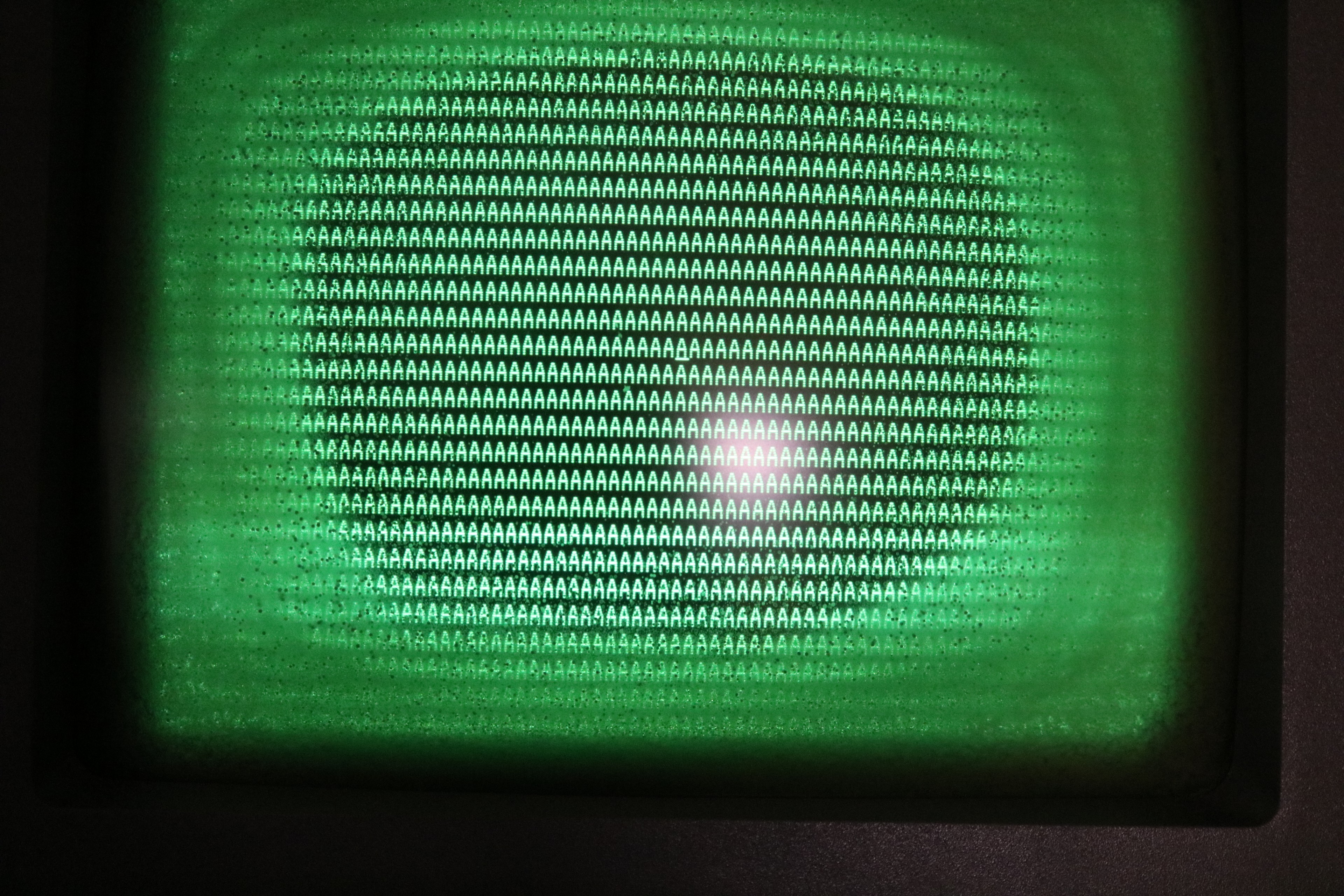
- Set the display memory to the letter “A”, repeated.
- Emit a single beep to indicate the diagnostic had completed.
- Wait forever.
While working through that diagnostic ROM, I found three additional problems:
- A bus transceiver associated with DMA at location 12G was bad. This one was hard to find, and only came from pulling and testing ICs.
- One of the DRAM ICs was bad. This was revealed by the Diagnostic ROM.
- The 8275 display controller was bad. This was an obvious fault as it was not producing video.
The bus transceiver and DRAM were easy enough to replace. The 8275 took some searching of the lab — I managed to locate a spare in my Intel iPDS “Personal Development System” and scavenged that one until a replacement could arrive from Jameco Electronics.
When it was all said and done, I had replaced 30 ICs in order to find the four bad ones. Here is my CPU board with many ICs now socketed:
At this point, my diagnostic ROM was succeeding, all the way through:
Problem #4: Power Supply Failure
While I was preparing to shoot the youtube video on the successful restoration, the machine started beeping and the LEDs started flickering. The power supply was failing. Below is a picture:
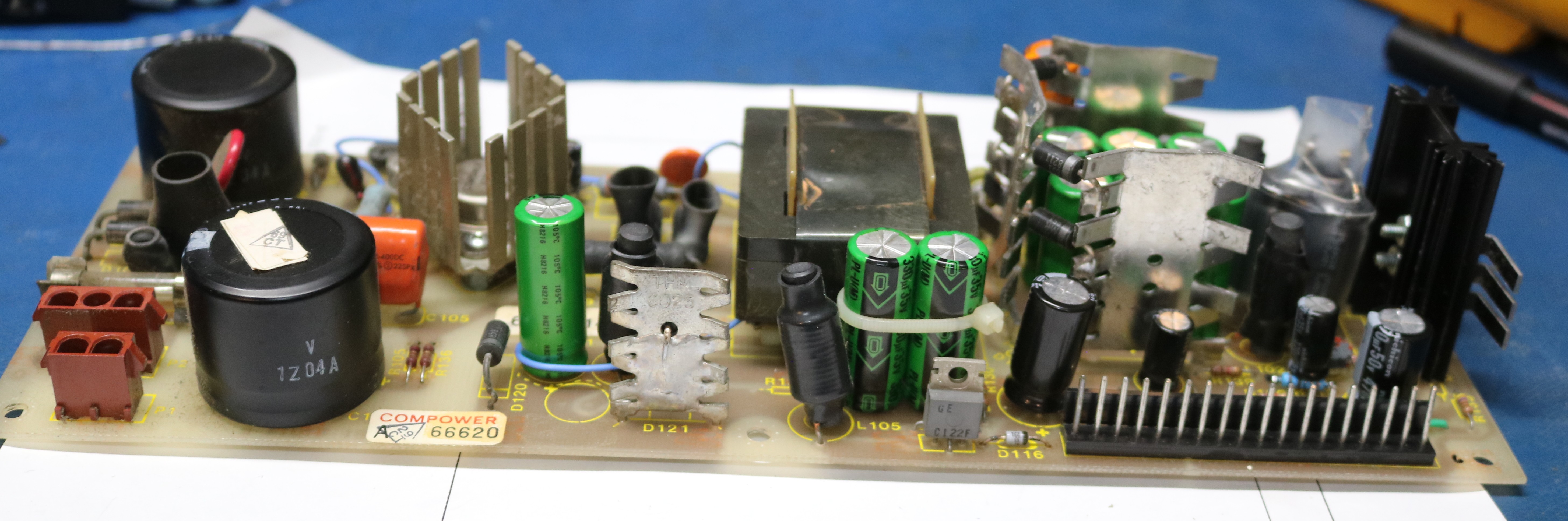
Whenever I see inconsistent voltage, it has usually been an issue with the output filter capacitor. In the picture above, I already replaced this cap, a 6800uf panasonic cap. That didn’t resolve the issue, and I ended up replacing all of the secondary capacitors:
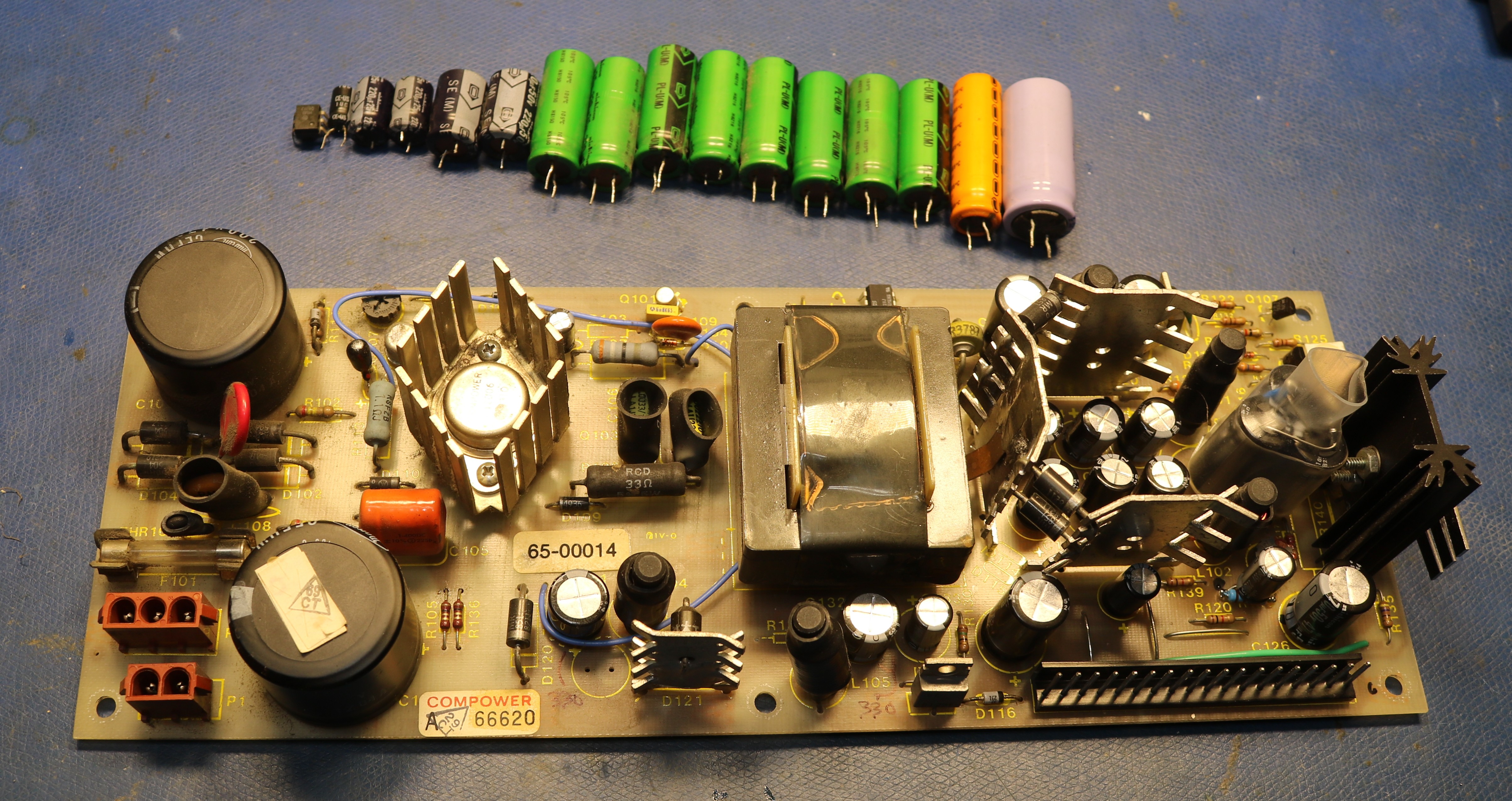
This still didn’t solve the issue, so I went poking around at other components. Insight came as I brushed my toothbrush against an H11A1 optoisolator and briefly it started working. It failed again shortly later, but this led me to pull the H11A1 and replace it. I first tried with a 4N27, but the low-load regulation was poor, so I searched the junk boxes and found a 4N25. After this the power supply was fixed.
Problem #5: Hard Drive Failure
Back when I received the machine in 2023, I pulled the HDD and imaged it using David Gesswein’s MFM emulator board. I use these MFM emulators in many projects — they’re great because they let you image a drive, then substitute the solid state emulator for the problematic drive. When I imaged it, there were many bad sectors. The emulator will retry them many times, and eventually manage to pull a valid image. But the drive itself was not reliable enough to boot the computer.
This took a little bit of work to figure out because of an oddity of how Convergent determines drive types. An MFM drive typically has four drive select lines: DS1, DS2, DS3, and DS4. The AWS only uses DS1 and DS2 for drive select. They repurposed the other two pins, DS3 and DS4 to determine drive type. The original HDD had bodge wires that pulled DS3 and DS4 to ground. My friend AJ at Forgotten Machines ran into the exact same issue, years before I did and documented this issue on his video at https://www.youtube.com/watch?v=-pVHknKpFiY.
The solution is to simple make the same jumper settings for DS3 and DS4 on the MFM emulator as were made on the original HDD.
So I pulled the drive back out, added bodge wires for DS3 and DS4, installed the emulator, and we got a successful boot:
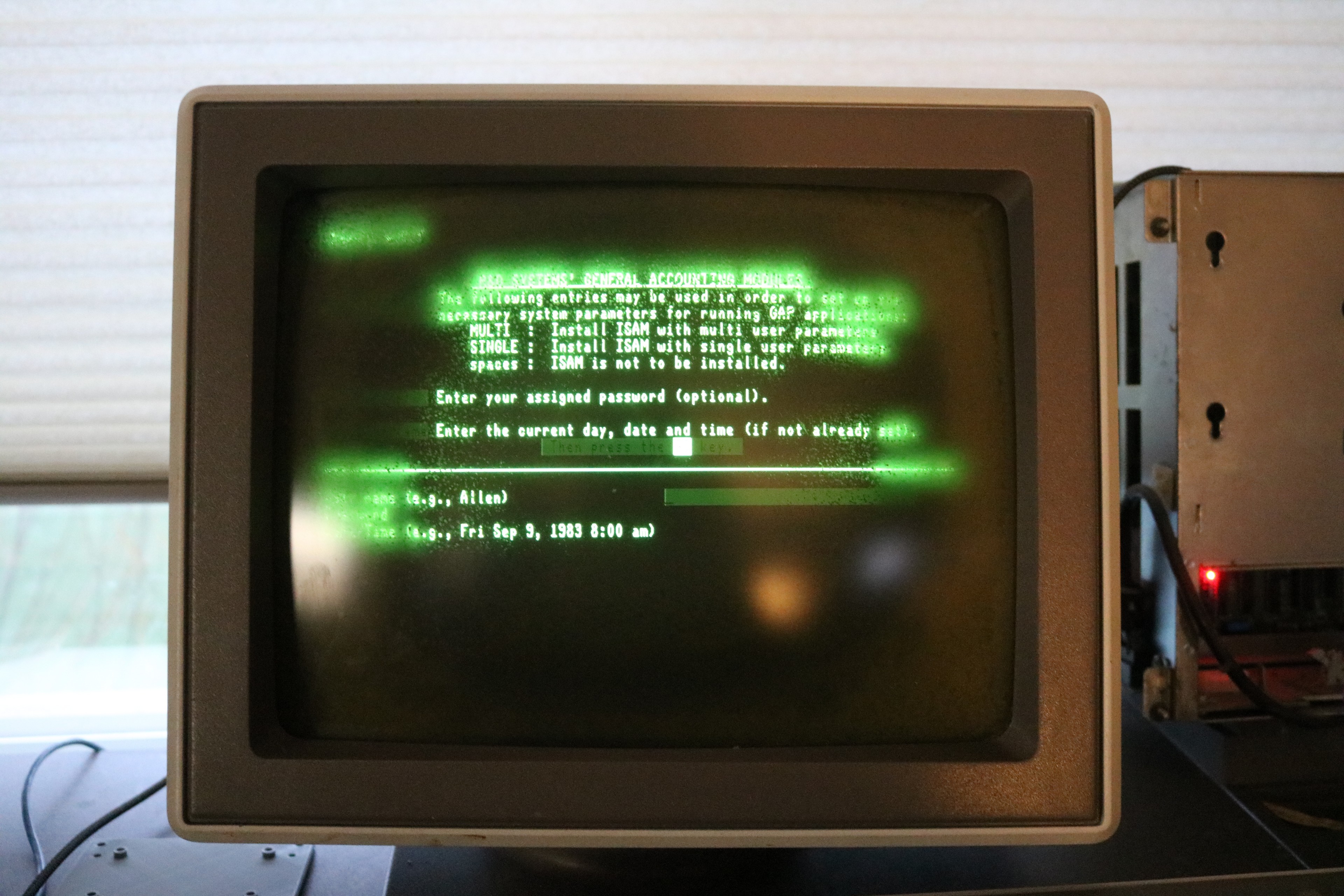
Problem #6: The Keyboard
I hit the Go key, which logged me in, but when I went to type in a command, the keyboard was behaving erratically. The symptoms were that half the keys didn’t work at all. The other half when pressed would emit two keystrokes — their own key and the key to their left.
The keyboard, like many keyboard designs, is arranged into rows and columns. If half of the keys weren’t working, and there was a clear pattern where it was every other column, then the problem had to be with the keyboard encoder or the keyboard microcontroller. I cracked open the keyboard:
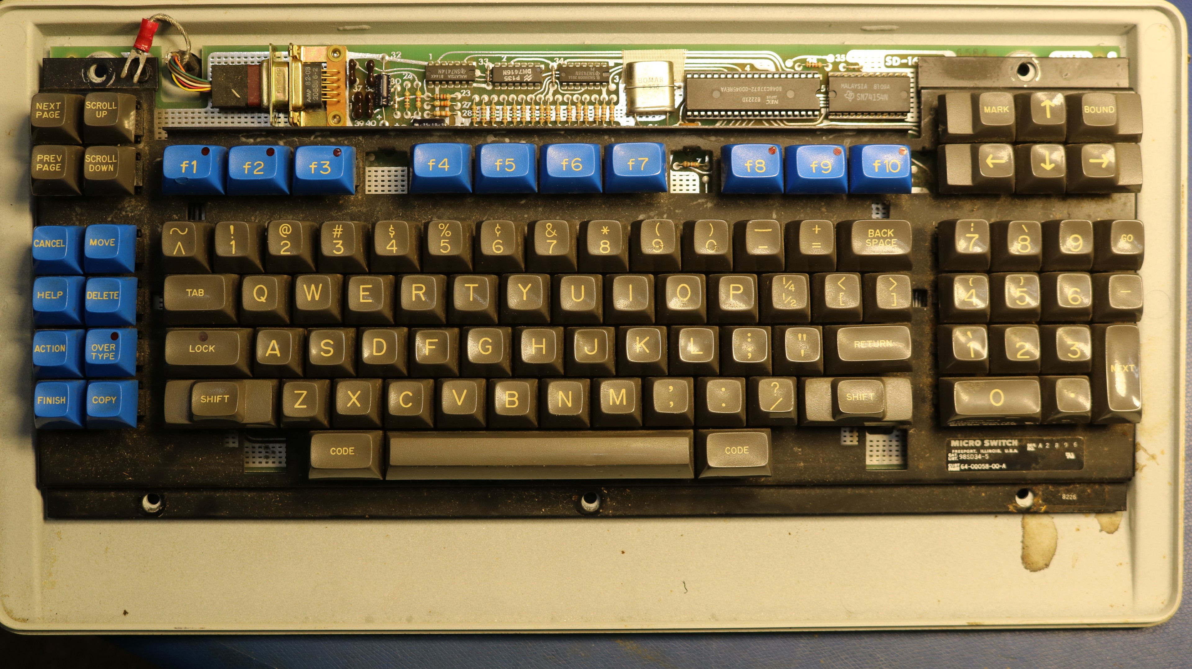
The keyboard column encoder is a 74154 in the upper right corner. I pulled it and put it in my tester and it tested good. I then pulled the 8048 microcontroller (I had no way to test it or program a new one) and re-inserted it into the socket many times. Sometimes that will resolve a problem, if the contact between IC and socket is poor.
In this case, it was a success.
Problem #7: Floppy Drive
The floppy drive is bad too. I haven’t got around to this, and I don’t need it to work as the hard drive image is viable.
Eventually though I’m going to need to sort it out. It’s unclear if the issue is the FDD or the hard/floppy controller board.
Problem #8: Monitor Cataract
This was such an ordeal that I wrote an entire separate blog post on it, here: Monitor Cataract Repair on my Burroughs B21 Vintage Computer CRT
Problem #9: The keyboard cable went bad
While I was trying to film the post-screen-repair video, the keyboard became fully nonresponsive. The AWS keyboard uses a simple serial protocol at approximately 1200 baud. It was a simple matter to put an oscilloscope at various points, looking for communication between computer and keyboard. My initial assumption was that it was either the TTL buffers inside the keyboard or inside the computer, but it turned out to be something as mundane as an intermittent pin on the DE9 connector on the keyboard cable. Unfortunately, the connectors on this cable are made from moulded rubber, and while I tried to cut into one for repair, I was not successful. I had to make myself a new cable.
Problem #10: The power switch broke
After I fixed the keyboard, the power switch failed. It failed in such a way that it would not turn on — I had to continuously hold the power button in for it to work. The power button is a DLA3A6V made by Oslo Controls. I was not able to source a replacement, so I jumpered the wires across internally, and use an external switch to turn the computer on and off.
There are some relatively close replacements on digikey, but the price is high (approximately $20) and they have a different color and a different voltage for the built-in light. I’m hesitant to put work into replacing it.
Problem #11: The “Go” key is intermittent
As can be seen in the videos, the Go key was intermittent. Sometimes I had to press it several times to get it to register. Disassembling the keyboard showed flux residue on the Go key, indicating it had been previously replaced. These keyboard use hall effect switches, part number 4B3S made by microswitch. I have some used replacements on order from eBay. In the meantime, I swapped the Go key and the adjacent “9” key from the numeric keypad.
These hall effect switches use four wires — +5V, two signal pins, and GND. They are scanned in a matrix similar to most keyboards. When a key is pressed, the hall effect switch will propagate the signal from one signal pin to the other (so the keyboard and strobe columns and read the result back as rows, or vice-versa).
I think the issue may have been a cold solder joint in the previous repair. These switches are very sensitive to solder temperature — the data sheet say 260C for no more than 2 seconds — and if you heat them up too hot, the pins may come loose from a tiny internal circuit board. So be very careful soldering these microswitch hall effect keyswitches. They’re also a pain to remove.
Resources
- my github repo at https://github.com/sbelectronics/aws contains the diagnostic monitor ROM I made, as well as other resources.