In this blog post, I restore a vintage Sharp PC-5000
Background
As people may have noticed from my other blog posts, I’m a collector of bubble memory and computers that use bubble memory. The Sharp PC-5000 is one of two noteworthy laptops that use bubble memory, the other one being the Grid Compass. The Sharp uses Hitachi bubble memory whereas the Grid uses Intel.
The Sharp PC-5000 features 128 KB (1 megabit) of bubble memory. This provides nonvolatile storage for programs and data. The computer also features 192 KB of RAM, which is where the built in DOS 2.0 is located. They went with a hybrid approach where the bubble memory cartridge holds the filesystem, with (my hypothesis) file entries that point to ROM for the portions that are DOS — things like the typical dos hidden and system files, command.com, edlin.com, etc. This means that you have most of the 128KB of the bubble cartridge available for use. It also means the system won’t boot DOS or BASIC without a bubble cartridge. Even though the data is in ROM, the filesystem doesn’t exist without the cartridge.
I’d been looking for a Sharp PC-5000 for a long time, and finally in January of 2026 one appeared on eBay for a decent price.
A request…
Before we get into the restoration, I am looking for two things:
- A replacement screen for my PC-5000, or if a screen can’t be found, a donor PC-5000 with a good screen.
- An external floppy drive for the PC-5000, either a CE-510F or a CE0513F.
If you have either of these, please shoot me an email at smbaker@gmail.com.
Now, back to our regularly scheduled programming…
Problem #1: The Power Supply
I don’t really expect bargain-priced items on eBay to work right, and this one was no exception. When I plugged in my bench power supply (note: the jack is center negative), absolutely nothing happened. There was a small blip on current draw, enough to maybe charge a capacitor, and then it went back down to zero milliamps. I tried the power switch then the op/charge switch to no avail. The power supply was dead…
The power supply has two stages. The following picture from from the Vintage Computer Foundation Forums, where voidstar78 posted a schematic snippet from the service manual:
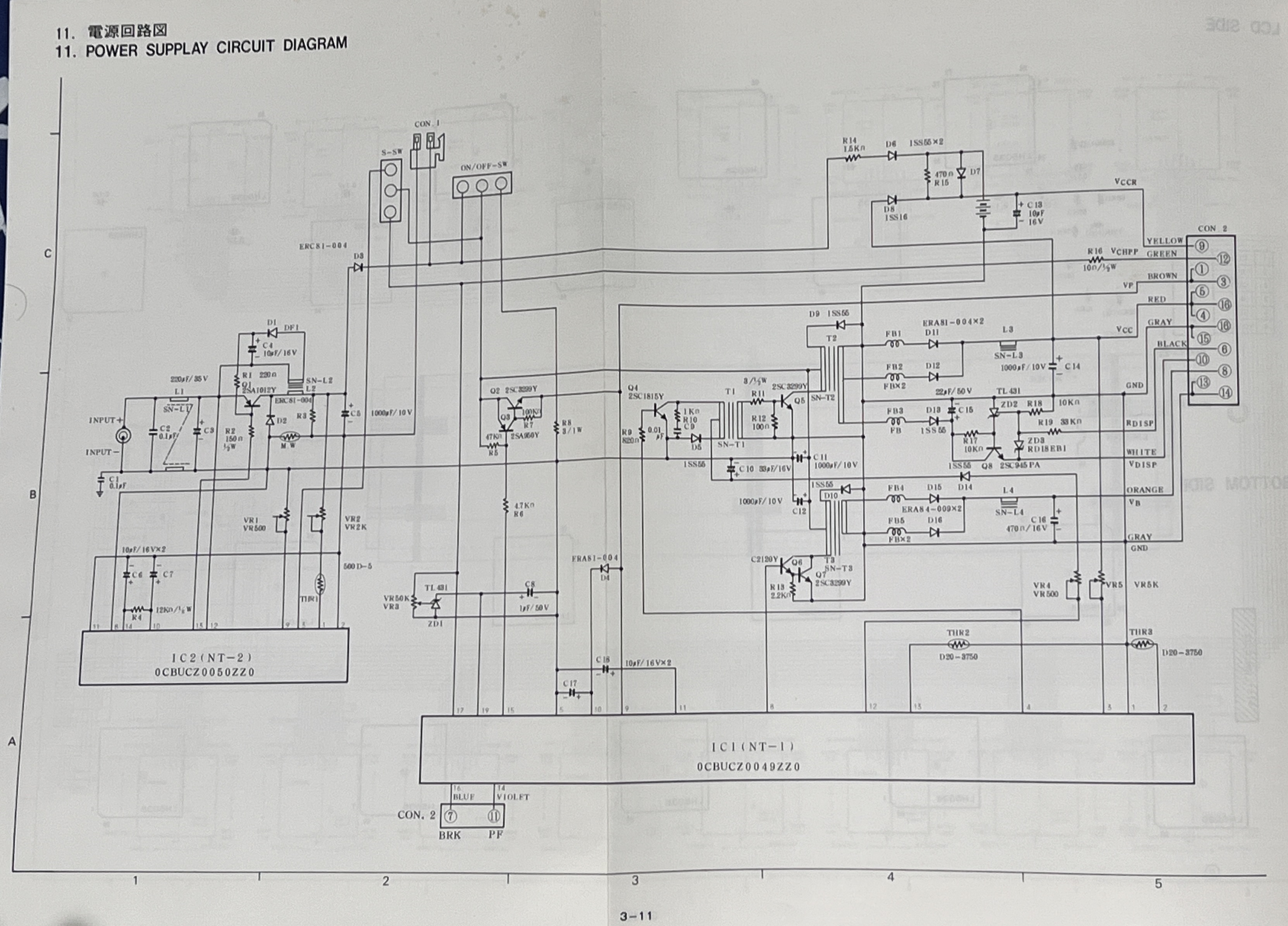
The first stage, on the left, converts the incoming +15VDC power into approximately 6VDC that is used to charge the battery and supply power to the second stage. The second stage converts the 6VDC from the battery into four voltages:
- +5VDC to power logic circuits
- -12VDC for RS232 drivers
- +16VDC to +19VDC as a variable power for LCD contrast, controlled by an external potentiometer
There’s also some signals that go out to alert the system to power failure — bubble memories must learn of power failure before the power actually fails, or data may be lost. There’s an oboard nicad battery with power to sustain the real time clock. There’s raw battery power output that goes to the bubble controller. Mostly I was concerned with the base +5, -12, and 16-19 power. I opened up the computer so I could have a look:
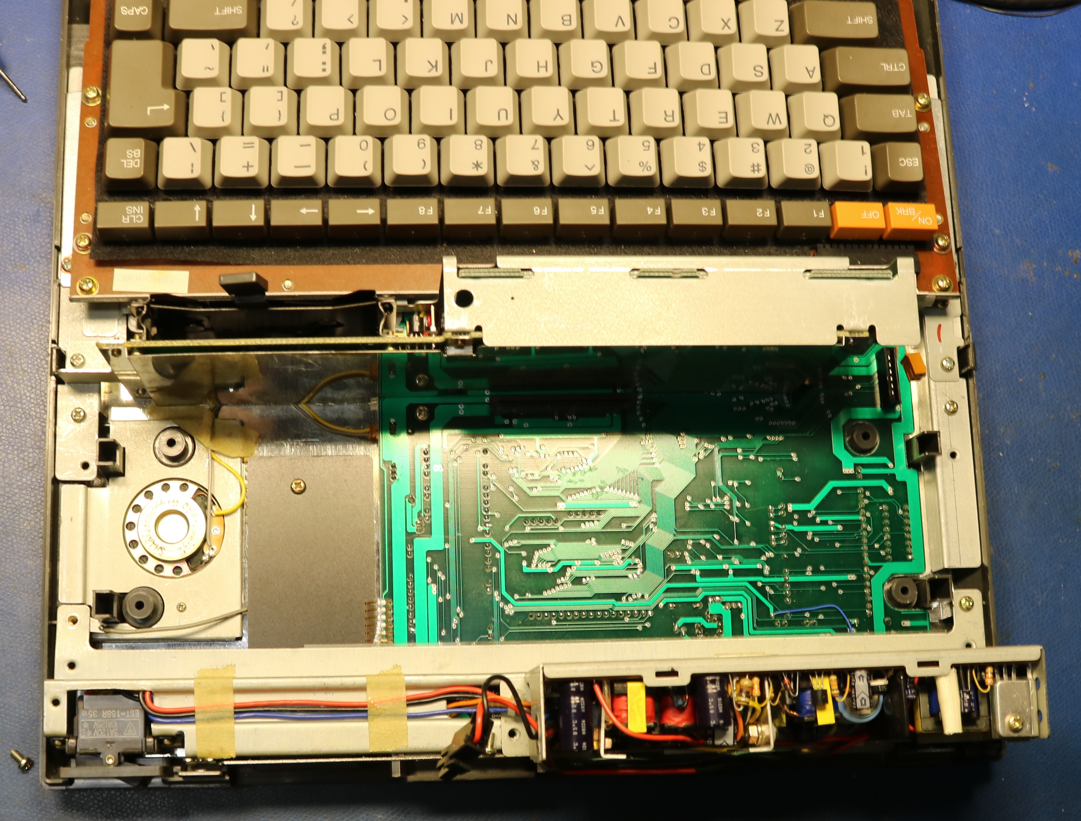
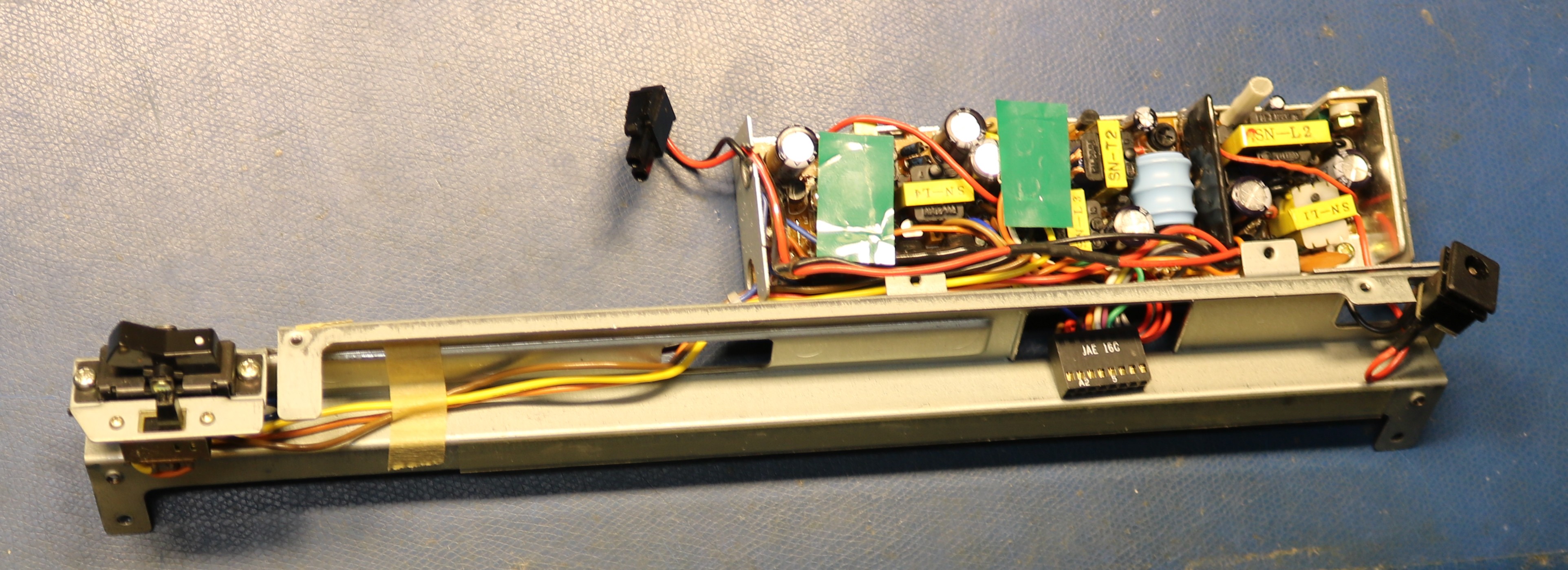
You can see that the power supply is in the back half. To get it out, we have to remove a small metal subframe and disconnect some connectors:
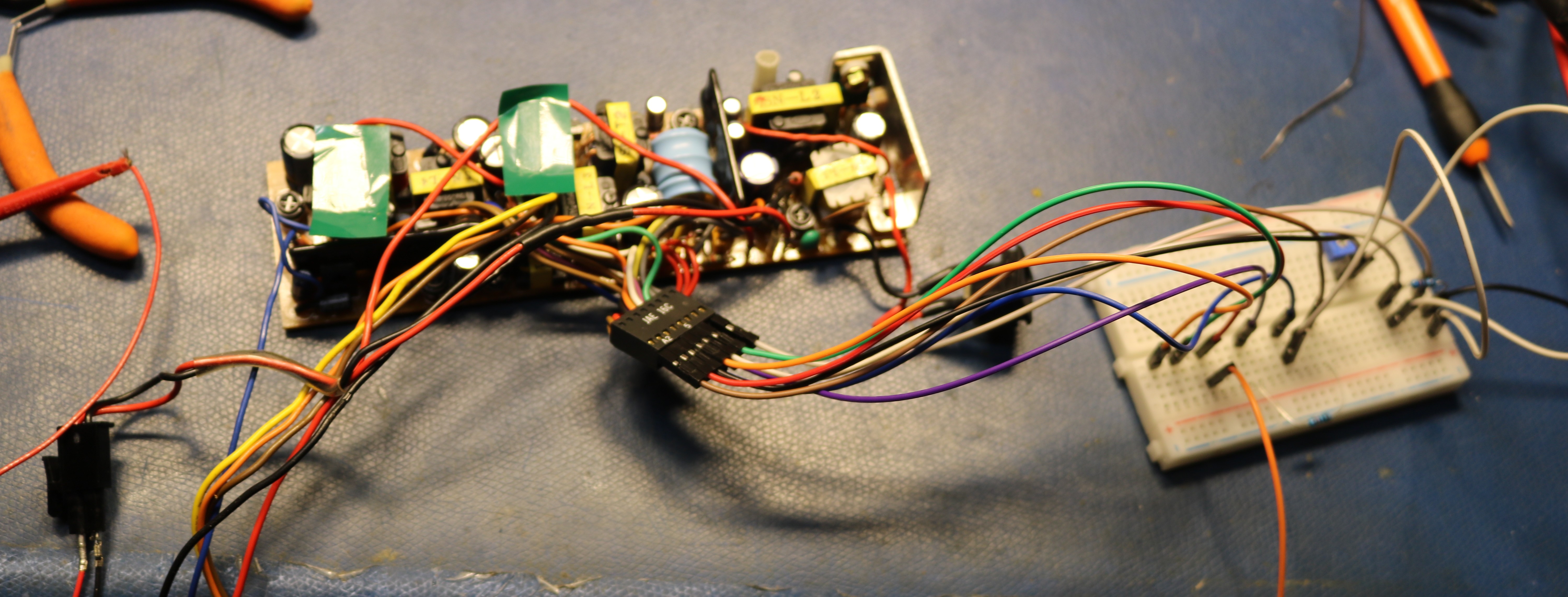
I ended up replacing all the capacitors on the power supply board. The only one that tested to be “known bad” was a capacitor right next to the input barrel jack. Even after replacing all the capacitors, the first stage of the power supply did not work. I suspect that what happened was that given this has a center-negative power jack, someone probably plugged in a center-positive power supply, damaging the primary filter capacity, but also destroying the regulator IC that controlled the primary phase of the power supply. There’s no replacement available. However, it is possible to power up the secondary supply, by supplying +6VDC to the battery connector. There are instructions in the service manual for doing this, as well as testing all of the outputs. I rigged up the power supply on my bench:
The secondary supply tested out good, though it did need some adjustment to bring the +5VDC output to specification. After this, I reassembled the computer. I still didn’t have video output, so I had a look at the LCD panel and found some more damaged components:
This appeared to be an 0.1uF ceramic. Note the flex cable and the small black wire that go to the LCD. The black wire only is used for RFI shielding to a metal plate in the case and is not electrically important. While working on this, I did remove and reseat the flex capable.
I found when powering the computer via the battery connector, I had to supply at least 1.5A, preferably even 2A. Otherwise the power supply would not start reliably. When I powered it up, I finally had a screen.
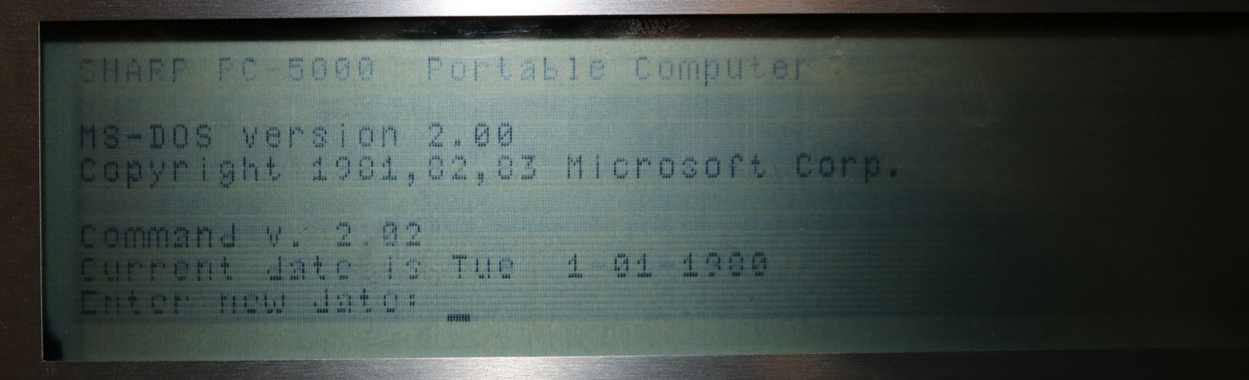
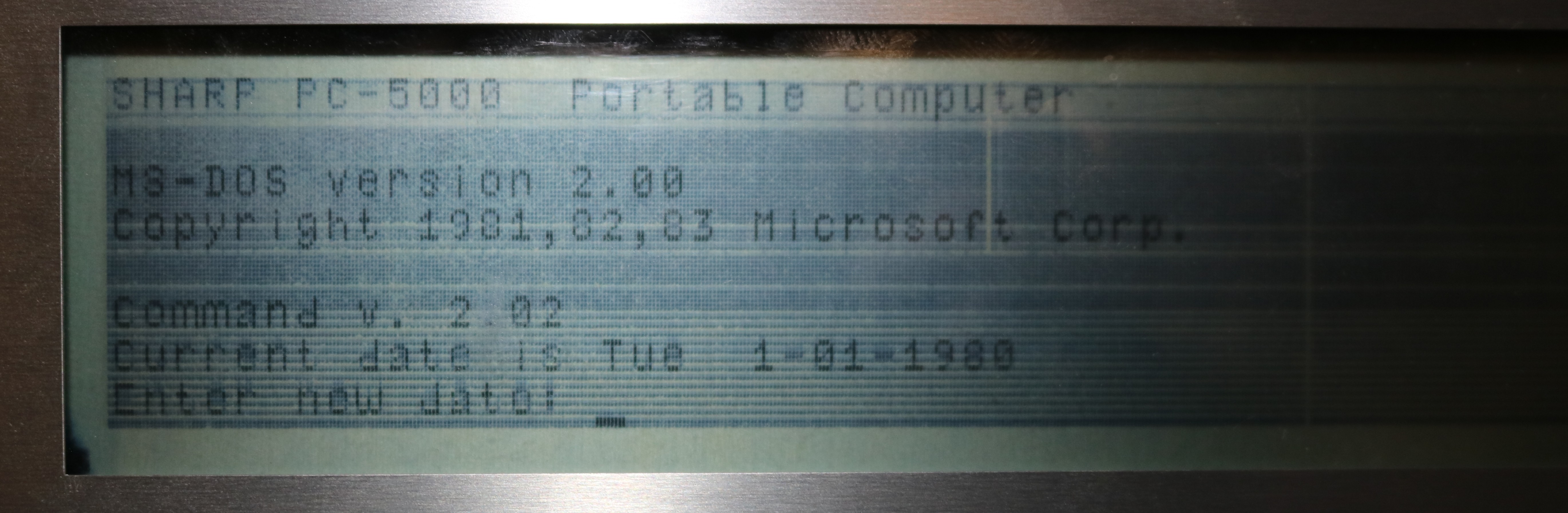
First Boot
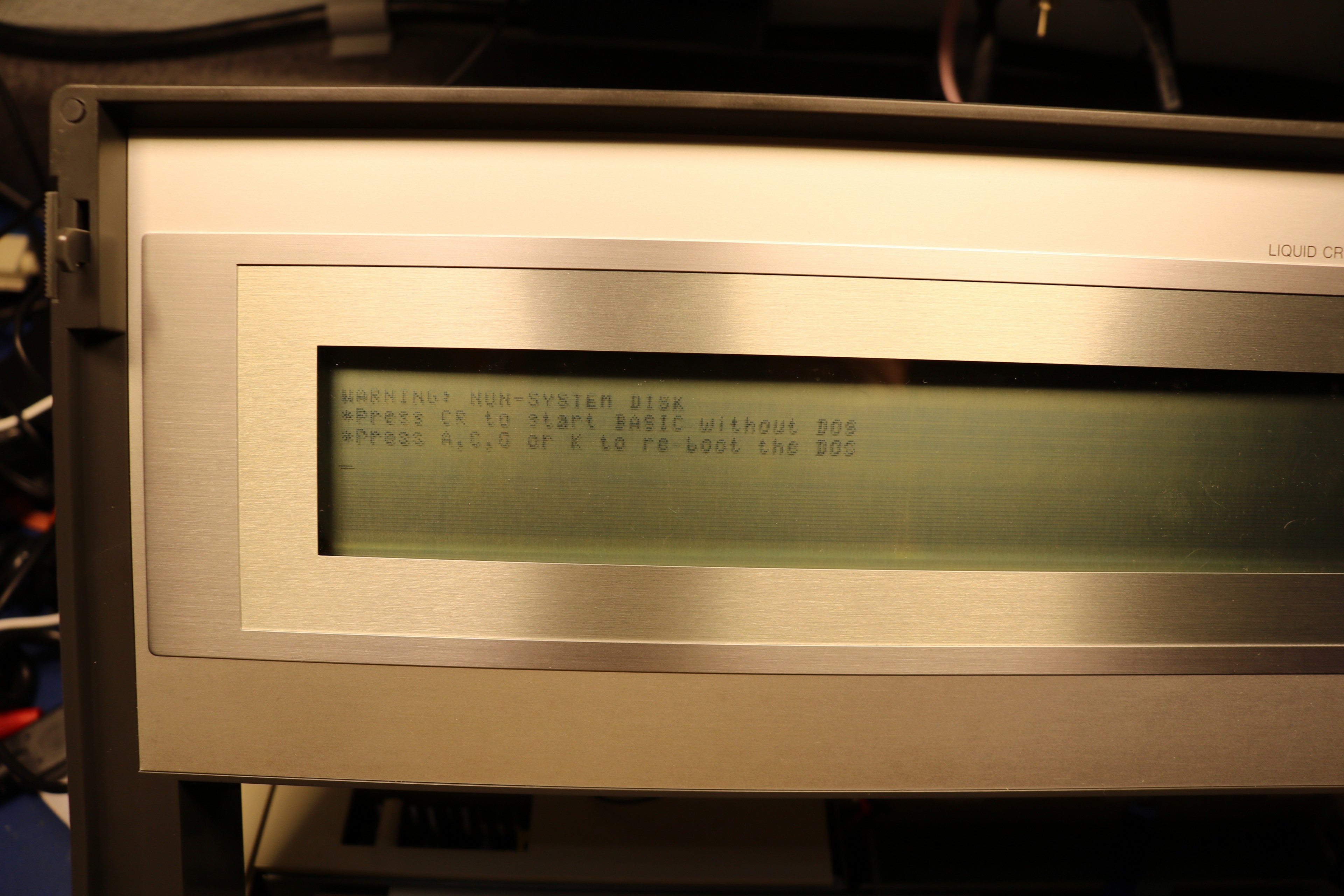
The screen was faint, but readable. There are several horizontal lines that are so faint that they might as well be missing. We’ll get to that later. But at least we had visible text, and a prompt. I hit enter, but BASIC did not load:
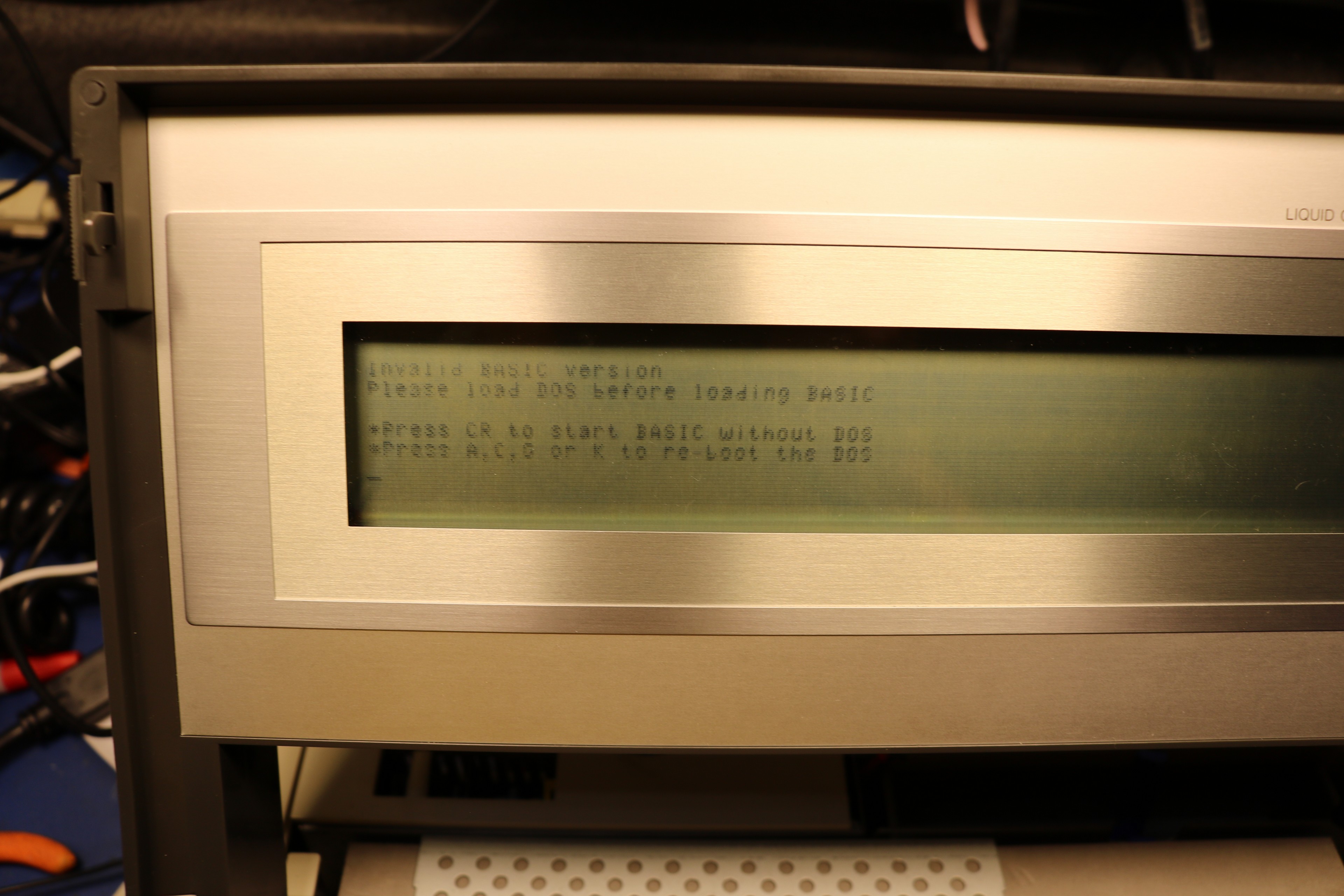
The reason for this restriction is how the operating system is designed. In its default configuration (i.e. without an external floppy drive), this is fundamentally an MS-DOS computer, with DOS almost entirely in ROM. DOS requires a storage device, and this storage device is the internal bubble memory cartridge. The bubble memory cartridge comes with a stubbed out filesystem that includes the typical DOS files — command.com, edlin.com, etc. It also includes BASICEXE.EXE and BASIC.COM. My understanding is that the contents of BASICEXE.EXE is literally the contents of the BASIC ROM. So without DOS, you can’t have these files, and without these files, you can’t run BASIC.
There is some evidence that the computer originally came with a BASIC option that could execute directly from ROM, without DOS, probably using the cassette interface on the back of the laptop for storage. I’m not sure if that ever made it to production.
Problem #2: The S-Key didn’t work
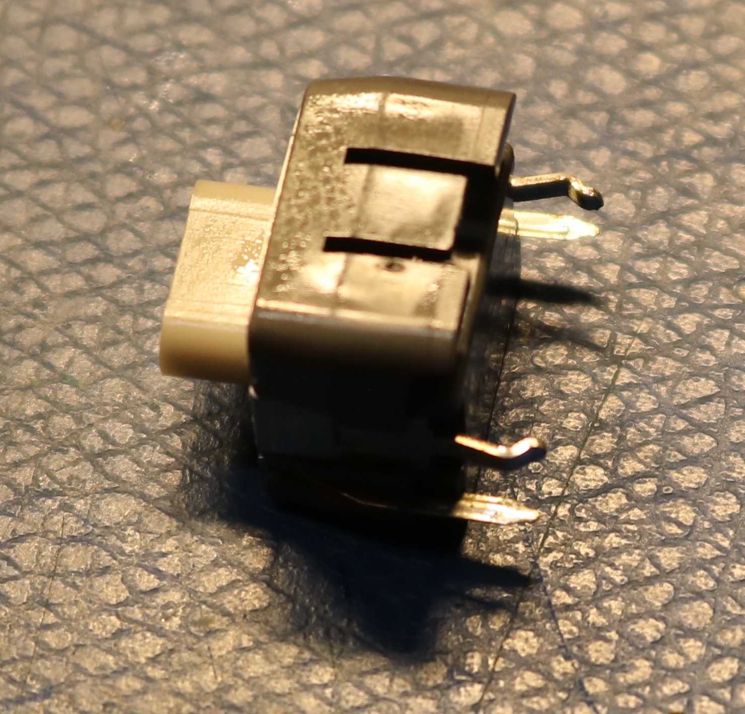
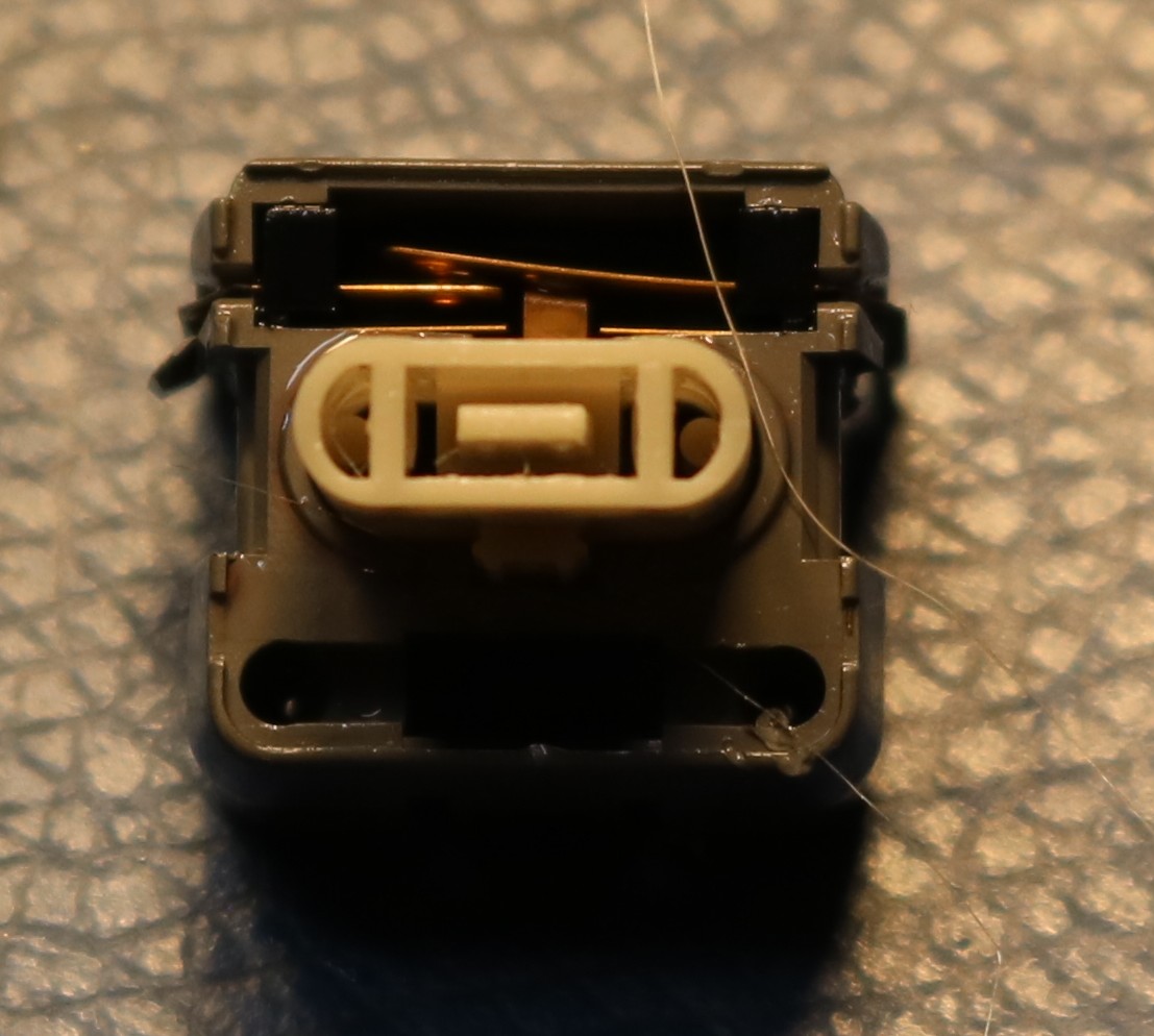
Once I installed a bubble memory cartridge and DOS loaded, I tried to run BASIC, but my S key didn’t work. You can’t have BASIC without an S. I tried all the keys, and it turned out that ‘Q’ and ‘1’ were also nonfunctional. I pulled the keyboard to have a look:
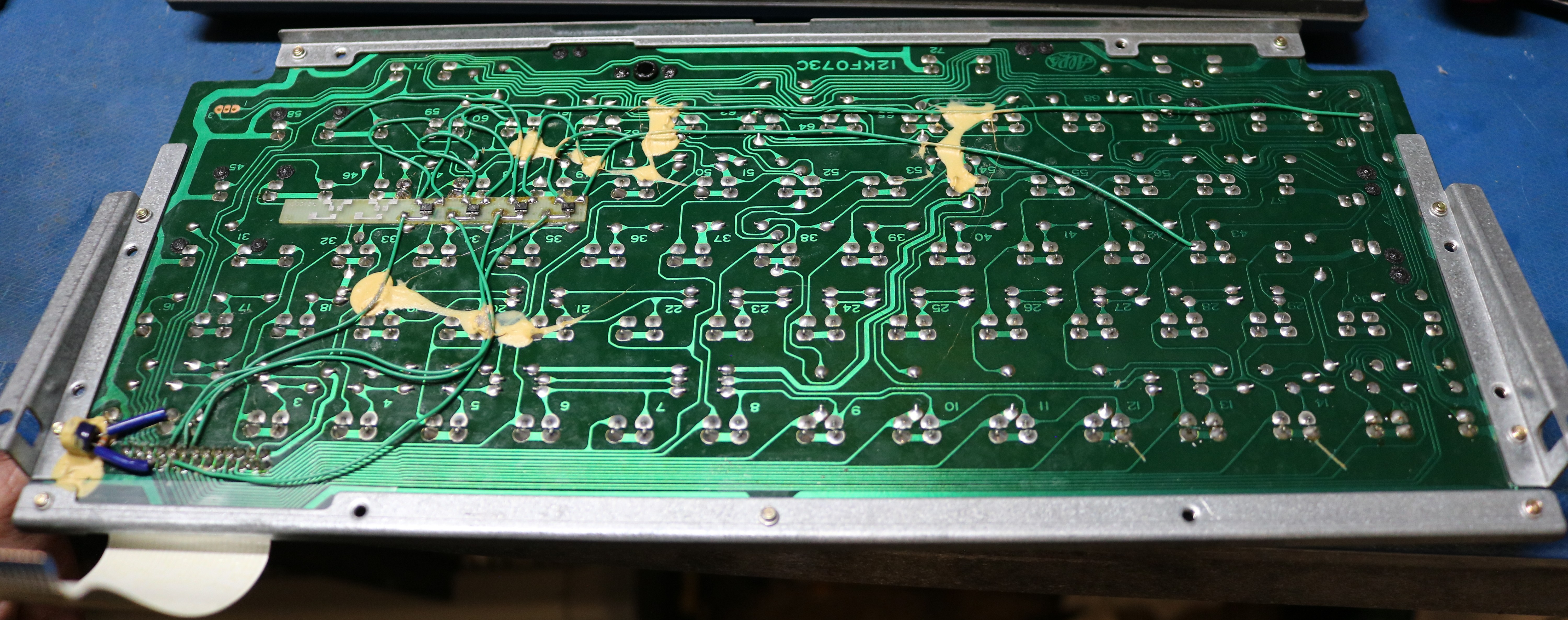
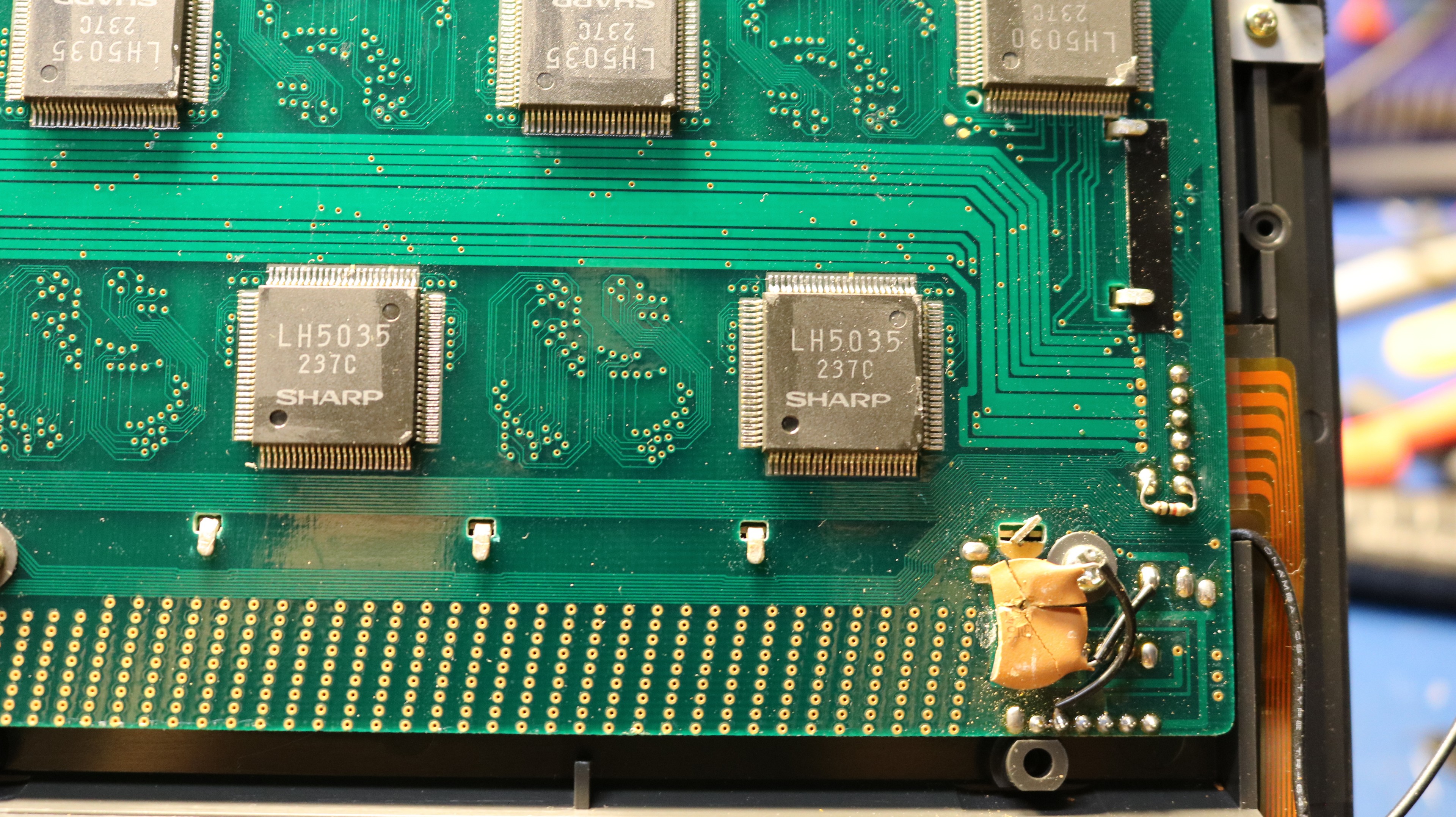
Note that there’s a flexible ribbon connector that connects the keyboard to the main board. Also note the great number of bodge wires, and what appears to be a small pcboard with some surface mount transistors. My theory on these bodges is that maybe they were used to support internationalization — there are at least two versions of the keyboard. Maybe the USA version needed some kind of key remapping. Alternatively, maybe it was needed for some kind of multi-key-rollover support. It seems strange to be hacked this way. I pulled the S key. It’s an alps:
There was nothing wrong with it, so I went back to looking at the keyboard. The ‘S’, ‘Q’, ‘1’, and ‘Off’ keys all share a column line to the keyboard encoder. I should have realized this initially — if multiple keys are not working, see if they have something in common. I traced this line all the way through to the flex ribbon and it was good. I reassembled the keyboard, and suddenly all four keys worked fine. I suspect it was just dirty contacts on the ribbon cable, and the act of removing the keyboard was sufficient to fix it. Often that’s the way with vintage electronics — take it apart and put it back together and it will start working.
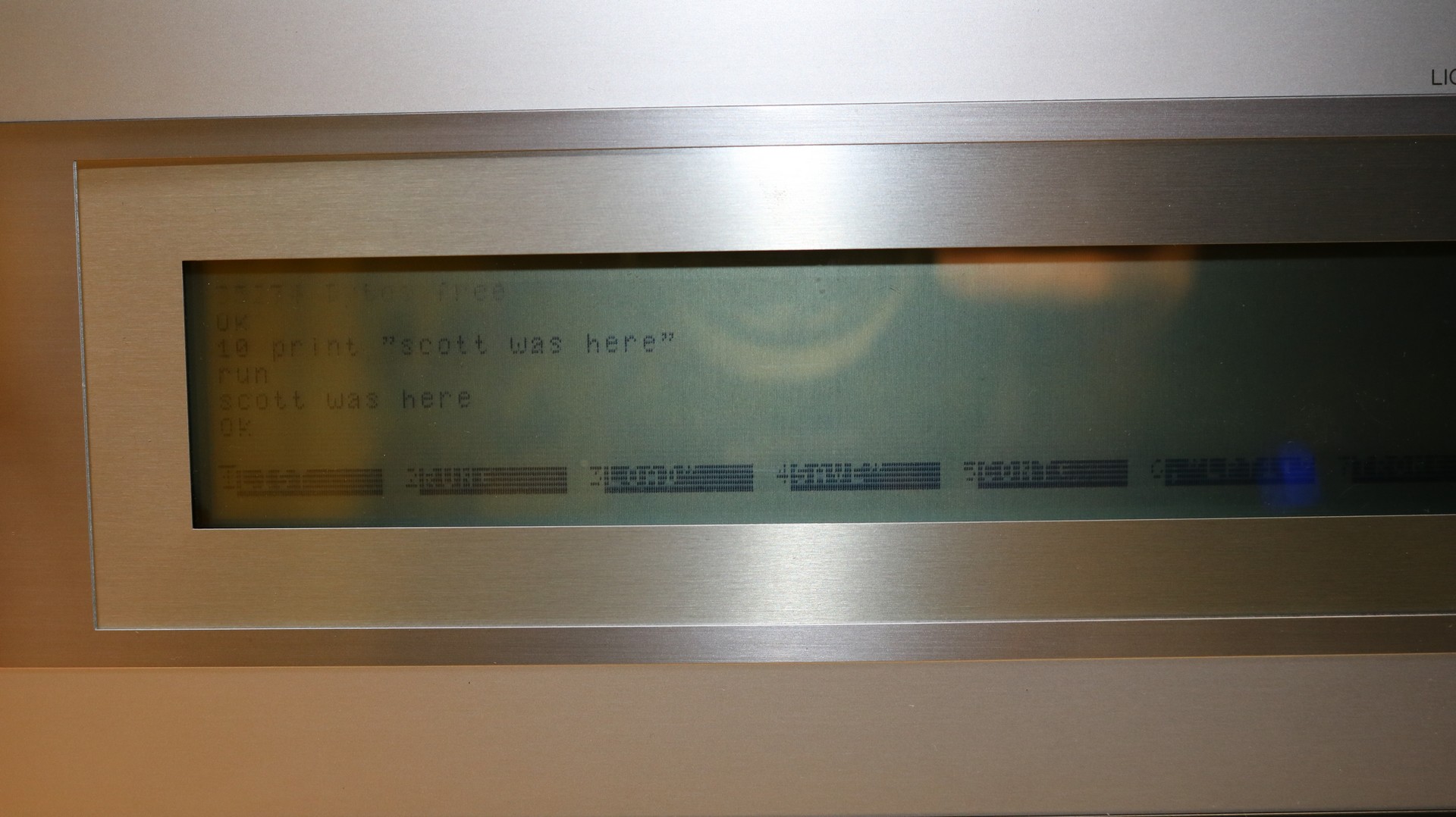
Running Basic
After fixing the keyboard, I was able to run basic:
Problem #3: The screen
The screen quality is really poor, as some horizontal lines are too faint to read. Most of the lines near the center of the screen are fine, but the one near the top and bottom are where most of the problem is. Here are a few pictures:
By cranking the contrast up to maximum, we can see the data is there, it’s just that some lines are much fainter than the others. I think the issue is with the common driver zebra strips (elastomeric connector) between the display pcboard and the glass LCD. I disassembled the screen:
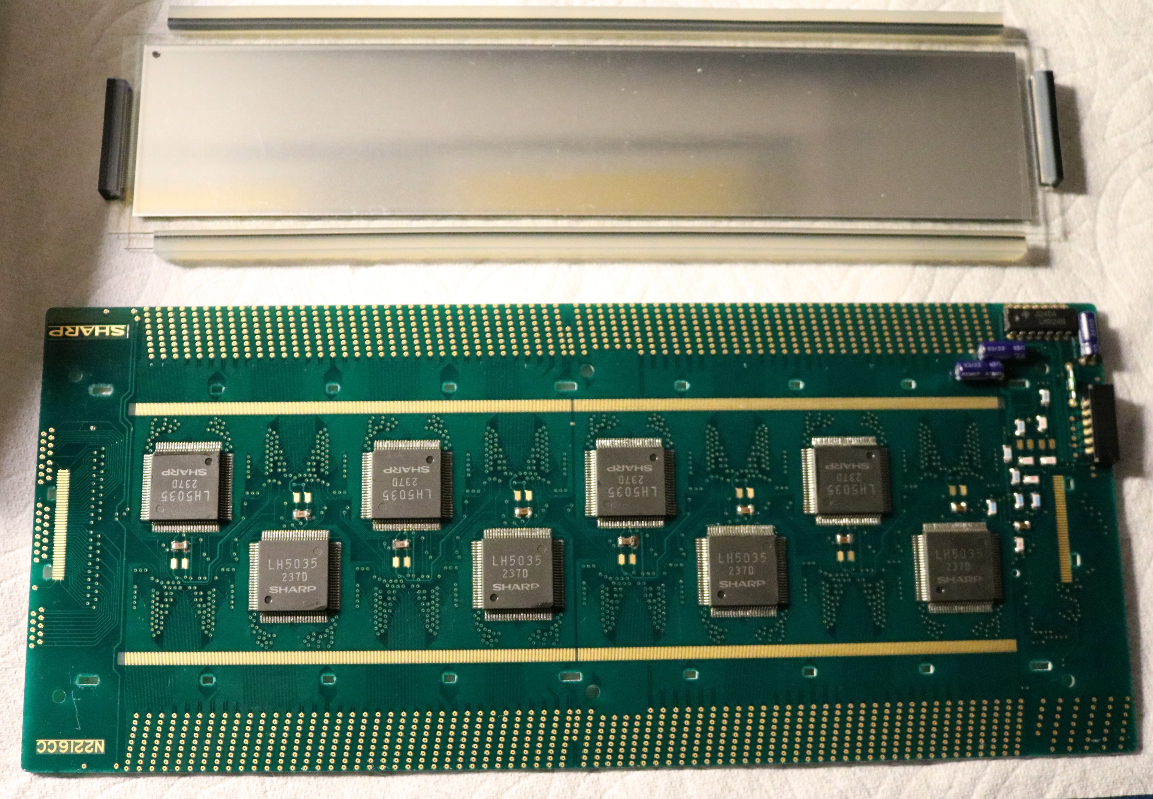
Above, you can see the disassembly of the screen. The pcboard is on the bottom and the LCD is at the top. There are four zebra strip connectors on the LCD. The long ones are approximately 230mm long, which is quite long and not very common. Getting this thing apart was a real pain as the zebra strips were effectively “glued” to the pcboard and the LCD. I’m not sure if this was actual glue, or if it was simply degradation of the silicone material in the zebra strips that led it to become “sticky”. There are clear indentations in the zebra strips where they have been pressed against the pcboard contacts for the last 40 years.
I haven’t reassembled it yet, and I do not have confidence…
Building an external disk drive
I would like to either source or build an external floppy drive, so I can do more with the PC-5000. The external floppy is more than just a drive. There’s an 8-bit bus between the PC-5000 and the external floppy. The floppy, based on pictures I’ve seen, implements a D765 floppy controller. Here’s a description of the external bus, from the documentation that voidstar78 provided:
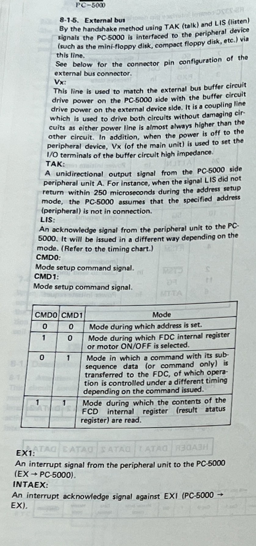
Here is a picture of the external controller in the CF-510F drive. We can see the D765AC floppy controller as well as the nearby external data separator. There are a lot of standard TTL logic ICs. It’s possible the rotary switch is used to set an identifier. My main observation is there’s not a lot going on here. We don’t have an onboard CPU or ROM. It’s basically just the disk controller that was moved external to the laptop.
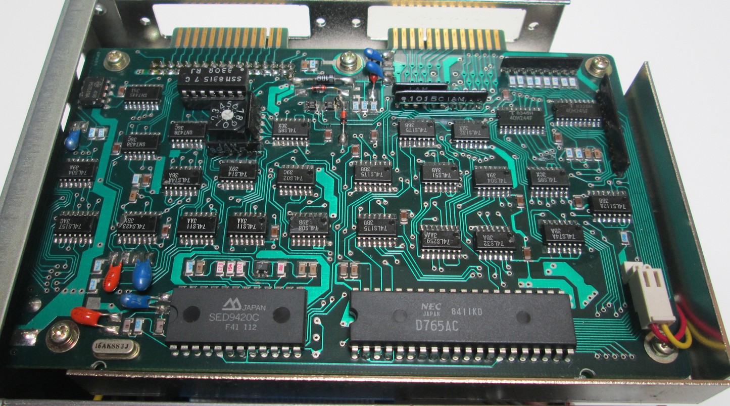
I think I could probably duplicate this, with some trial and error, from the picture and the bus description. The only thing I’m not sure about is that the D765 has two different registers that can be read: the master status register and the data register, and the mode bits in the external protocol specification only have one mode that pertains to reading things. Might need to put a logic analyzer on it and see what it actually does at runtime on the bus connector.
I am putting this effort on hold until the screen issues are resolved.