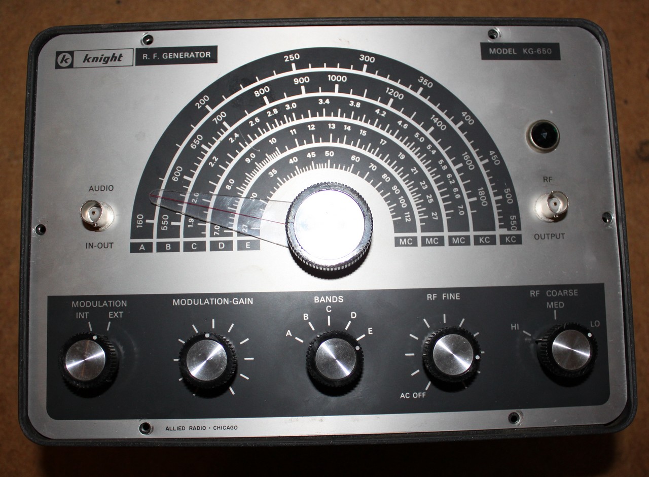
I decided that restoring old tube radios was to be my new hobby (Thanks, Nuts & Volts…) and I quickly realized that I could use an RF signal generator. Rather than do the sensible thing and buy something new, modern, tested, and functional, I decided to grab a 1959 Knight KG-650 RF Generator from ebay:
Here’s a picture of the RF generator, after a little bit of restoring:
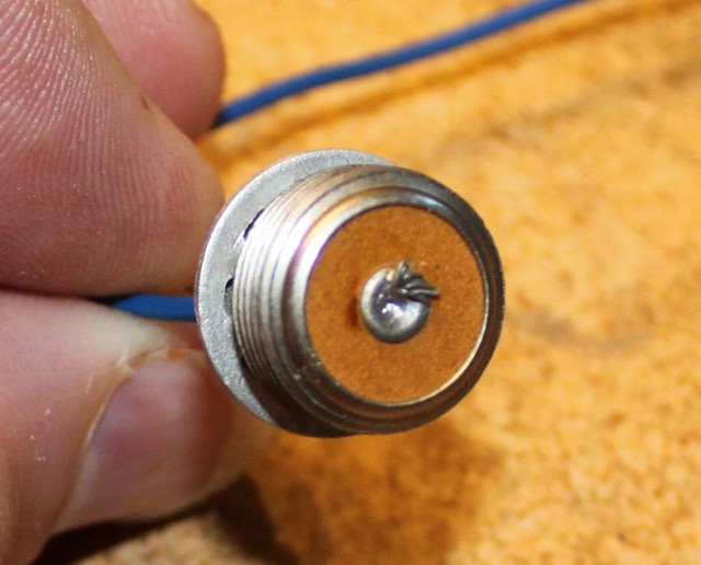
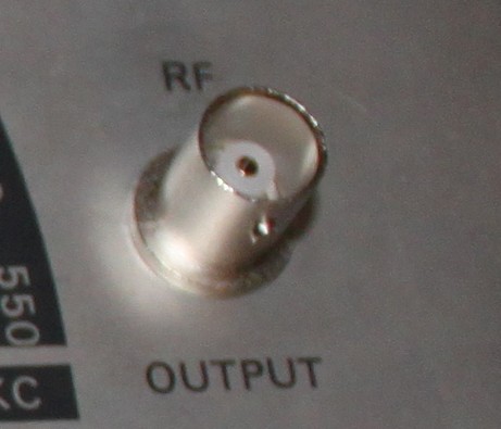
Before it even arrived, I realized that the test leads I have use BNC connectors, whereas the piece of ancient history that I ordered had some kind of funky 1950s RF connector that no longer exists:
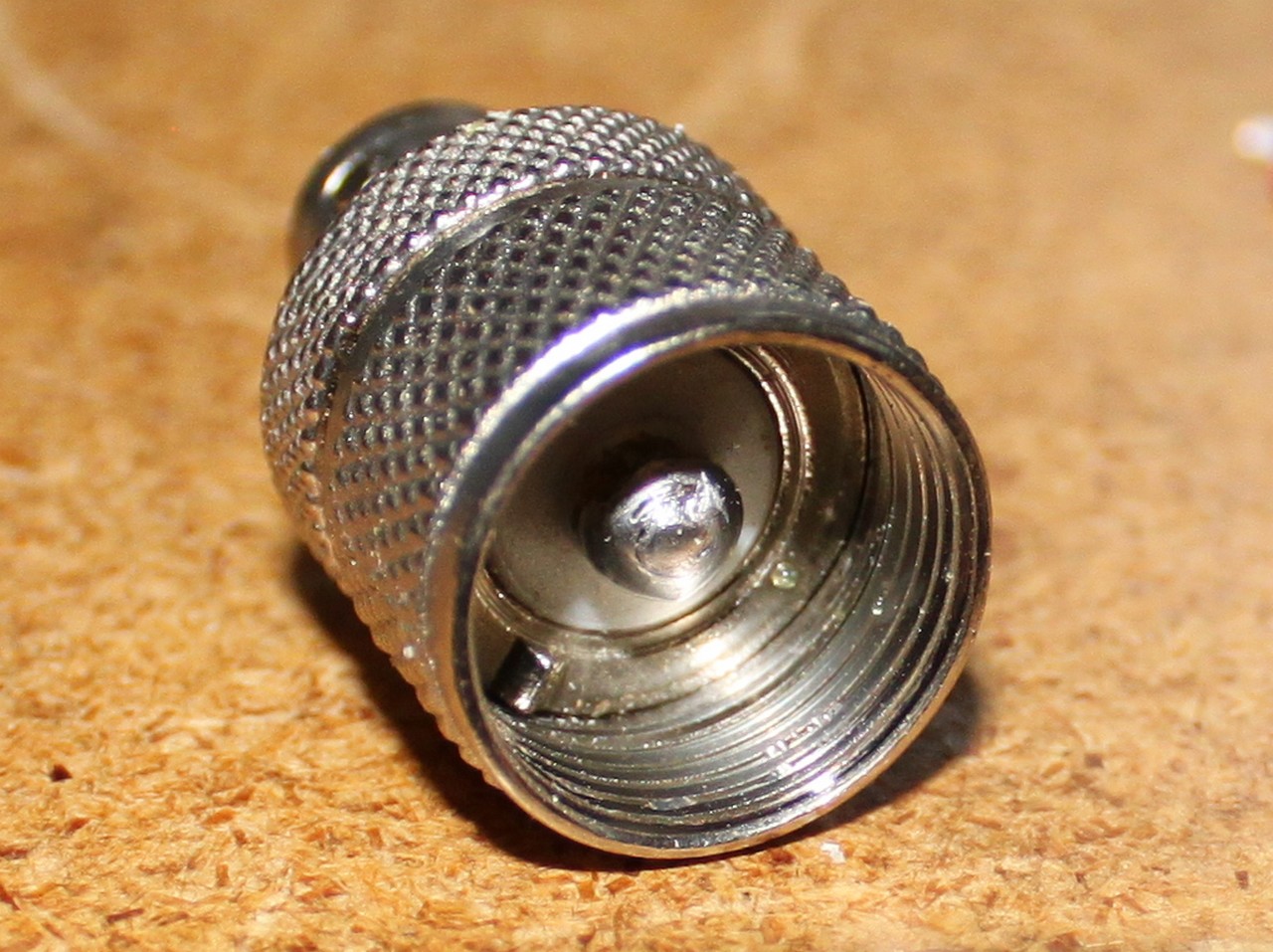
I found out online that I could cut the center pin in a PL259-BNC adapter down to about 1/4″ and that would fit the funky knight connector. So I did that. I actually cut it down a little too far, but some solder deposited on the stub of a center pin managed to make up the difference. The adapter worked.
However, it turned out to be a really stupid idea. I spent ~ $7 making this ugly adapter when I could have just bought some BNC jacks from digikey (P/N A97548-ND) and replaced the jacks in the signal generator with modern BNC jacks. I did that, at $1.74 per jack. They fit perfectly, and now I can attach modern test leads to the old RF generator without any issue.
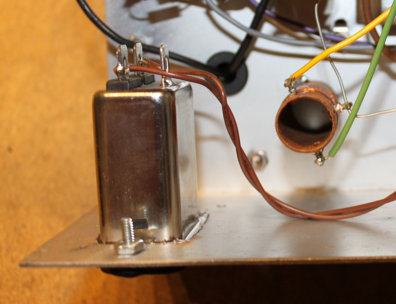
While I had it torn apart, I replaced the filter capacitor, because old filter capacitors are prone to failure.
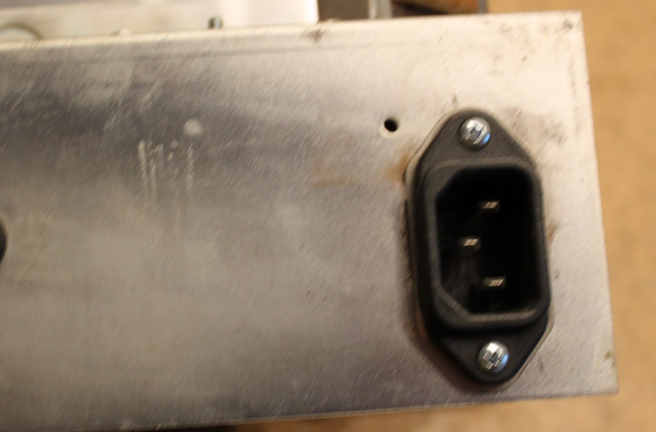
I also ditched the old non-polarized AC cable and replaced it with a receptacle for a modern AC cable, the type typically used by computers an test equipment. I like my test equipment to use standard power cables, and I like the safety of things being grounded, especially things that might have a hundred and twenty volts wandering around in them. It took some case surgery to make this happen:
This modification is a bit controversial, as it now means the KG-650’s BNC jacks are grounded. Some radios are hot chassis and non-polarized, which means one could encounter a radio with 120 VAC on the chassis. It would be really bad to connect a test lead ground to that. The answer is to use an isolation transformer on the radio under test — you really ought to be doing that anyway. However, it’s conceivable that one day a guy could forget, and turn some perfectly good test leads into a short-lived welder.
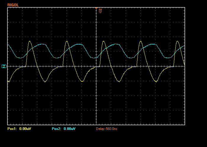
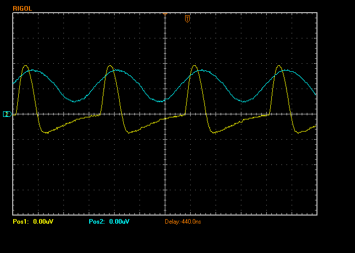
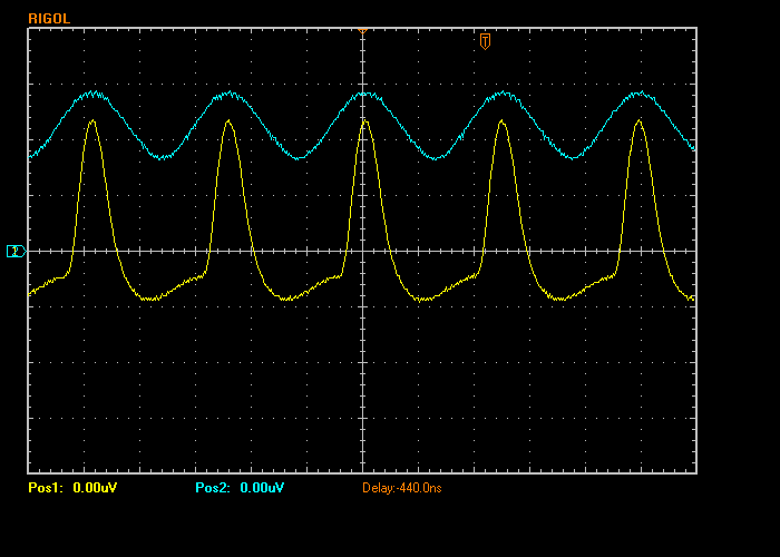
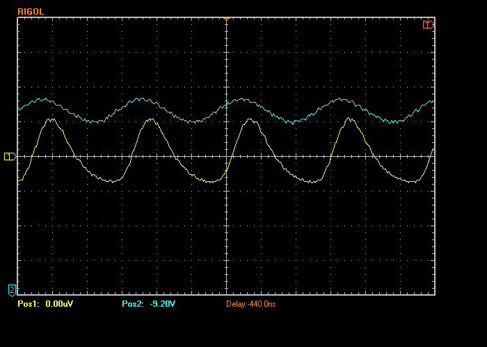
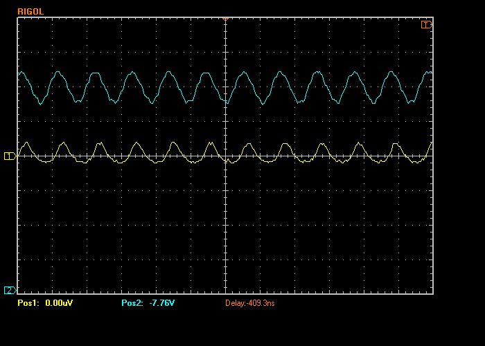
Next it was time to take a look at the output of this wonderful RF signal generator. Here are some screen shots using my Rigol DS-1052E. The yellow trace is connected to pin 3 of the 12AT7 tube (i.e. upstream of the RF attenuator) and the blue trace is connected to the pin 6 of the 12AT7 tube. The yellow trace approximates what you’ll see on the output of the instrument.
Holy Crap! What’s going on here? Those first two plots at Bands A and B are atrocious. The output vaguely resembles a sine wave, but it all truncated and crappy. At lease band C and D look a little better. NSE Labs at https://nselabs.wordpress.com/2015/03/01/knight-kg-650-improved/ reports similar problems with the KG-650, and resolved the issue by inserting a 2M pot between C8 and pin 6 of the 12AT7. The idea is that mixer stage of the 12AT7 is being over-driven. I have a 2M pot on order and am going to give this a shot. I expect similar results on Bands A and B, but I do wonder what the effect will be on bands C and D, whether the signal will be too low to be usable at those frequencies.
Band E could not be resolved with the ‘scope. Maybe something is broken.
Hi Scott,
I read with interest your mods to the kg-650, as I have recently purchased one also. I know very little about hollow state repair and nothing about solid state, and am just a hobbyist newbie at this point. I am still collecting my diagnostic equipment at this stage. I can’t find a manual for the 650, not even BAMA. They are out of print and should be public domain, but people are selling them for about $25. I was able to get the schematic from BAMA. Don’t know if you could help me with a few questions? 1)Is the filter cap the 470 MMFD? 2)When you ‘scoped the 650 via the 3 pin (12AX7, yellow trace) and 6 pin (12AT7, blue trace) would this have been done using 2 separate channels? I have a Tekronix 2246A scope but haven’t used it yet, so I’m trying to figure how to do the same test you did. And finally 3)what is a 2M pot? I’m curious if that helped with the 12AX7 being over driven, and perhaps a little more detail of the installation.
Thanks so much for your posting this information!
Rich Ferraro
Hey Rich,
The filter capacitor is a pair of 20uF capacitors with a 2.7K resistor between them. It’s marked C3 on the schematic. While these are technically two separate capacitors, old radios will often locate them in the same metal can. It’s been a while since I tore into my KG-650, but I think this was the case. Yes, I did use two channels on my scope (I have a rigol DS 1052 digital scope). “pot” stands for potentiometer, and 2M means 2 megohm (2,000,000 ohms). I haven’t modified mine with the pot, though I do plan on trying it out. Basically the idea came from the NSElabs blog post that I linked in my blog post. It seems like a good idea, though while I think it’ll correct the overdrive, it might lead to an underdrive situation in other bands.
Unfortunately, these old tube-based RF generators can be pretty mediocre when compared to a modern solid state design. I’m currently building a solid state RF generator described in the June 2014 issue of nuts and volts, and so far it seems a lot cleaner and more versatile than the KG-650.
Hello,
Do you have a copy of the KG-650 manual that you could email me?
Hey Michael, I don’t know if I have a link to the manual, but I do have one for the schematic: http://bama.edebris.com/download/knight/kg650/knight-kit-kg650-rf-signal-generator.pdf
I just drug out the one my Dad built in the 70’s? I also replaced the electrolytics . Seems to work except for the 27-115 band. At least my frequency counter does not track it. Have not tried the scope on it yet. Did you ever get the top band to work?
Thanks Jim NX0R