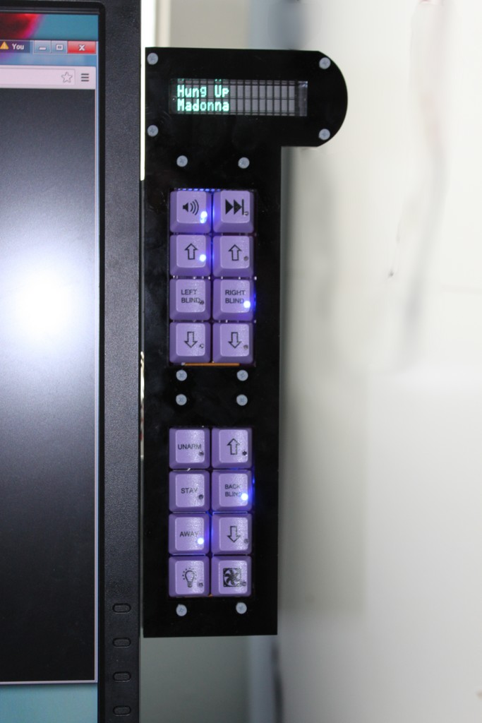
I’ve been a home automation enthusiast for at least a year, but I’ve never found a controller that I liked, so I built my own:
You can see the controller above attached to the side of my monitor. I used a black acrylic to match the aesthetics of the monitor. The purple keyswitches were because WASD Keyboards had blue on backorder that week (which turned out really fortunate, see below). The display is a VFD that’s described in another post on my blog.
I wanted the controller to be able to control all of the following things:
- Somfy Blinds
- Elk M1 Gold Alarm System
- Lights and Ceiling fan via ISY-994i Insteon Controller
- Scott’s Pandora Player
Let’s talk about each one of these systems in brief detail:
Somfy Blinds
The Somfy Blinds are controller by a somfy RTS-II interface. This is a little box that has a serial connection and sends the RF signals to the blinds. It supports three functions for each blind – up, down, and stop/preset. The up and down buttons will move the blind to the full up or full down position. The stop/preset button serves a dual function. If the blind is moving, it will immediately stop. If the blind is not moving, then it will move the blind to a user-configurable preset. I have my presets set about half way up, to block the sun when it’s in the mid-day position.
The Somfy controller is connected to a GlobalCache iTach ethernet-to-serial interface, which is in turn connected to a PoE (Power-over-Ethernet) receiver, and finally connected to my PoE switch.
The tl/dr is that you send a command like “0101U” (group1, blind1, up) to a particular ethernet port and the blind goes up.
Elk M1 Gold Alarm System
I’ve written a python library that talks to the Elk M1 Gold. It uses the Elk M1XEP ethernet expansion module. The protocol is fairly simple TCP-based. You can send commands to query the state of the alarm, to arm/disarm it, read the state of zones, etc.
ISY-994i Insteon Controller
The ISY-994i uses a REST API. That’s a fancy way of saying that it uses HTTP over TCP just like any other web server. You do a GET on a URL like “/rest/nodes/13/cmd/DON” and it turns the ligh on. Then you do a get on “/rest/nodes/13/cmd/DOF” and it turns the light back off. Easy.
Scott’s Pandora Player
I built my own Pandora player, also using a Raspberry Pi. It uses an opensource player called Pianobar to stream Pandora to a small digital amplified. On the pi, I run a django web server that gives simple instructions to pianobar to change channels or skip songs. I wrote up a simple based HTTP interface that lets me control the player remotely.
Okay, so now lets build some stuff
Controller Hardware
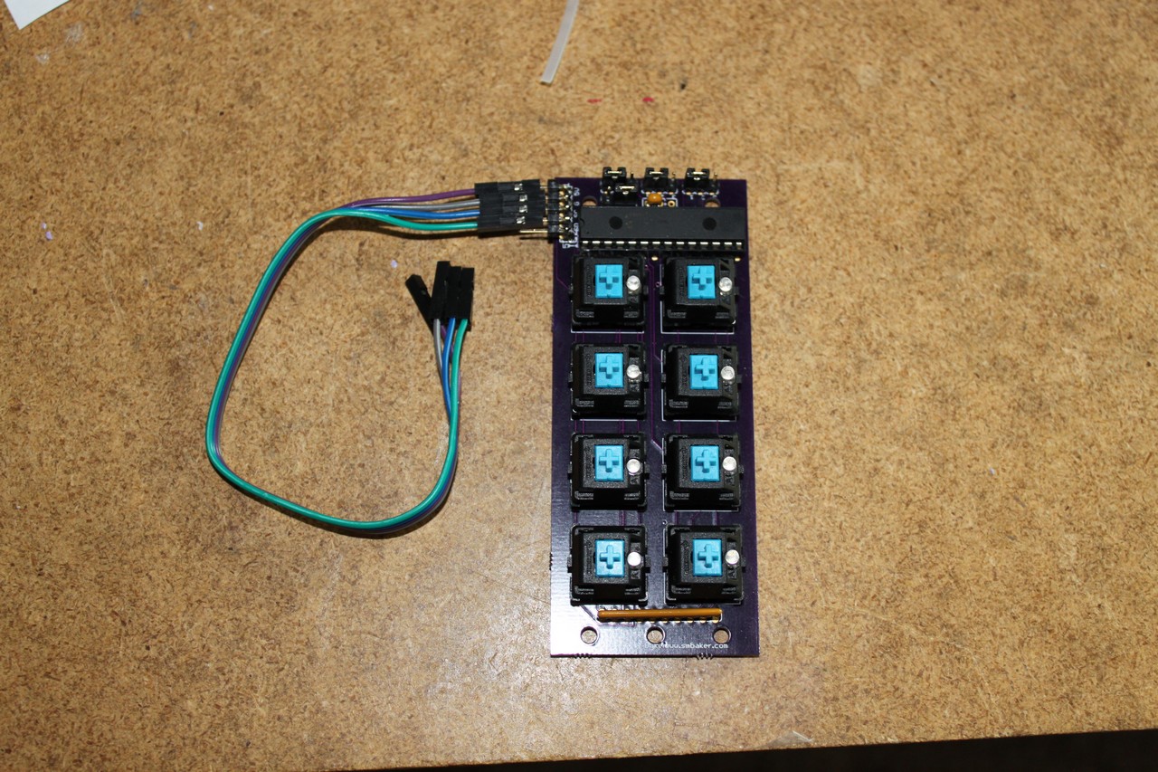
First we’re going to need keypads. I already designed a simple 2×8 keypad for the Nixie Calculator, but for the controller I really wanted to have the keypad have some little LEDs that would show state. This necessitated a little bit of redesign. I used a MCP23017 IO expander to give me 16 channels for digital IO from an I2C bus. Eight of these channels are connected as inputs to the switches, and the other eight are connected to the LEDs as indicators.
As you can see, I used the same Cherry MX Blue keyswitches that I used for the Nixie Tube Calculator. These switches have removable keycaps, and the picture above shows it with the keycaps removed, so you can see the LEDs. The Cherry keyswitches have an unpopulated spot on each one for the LED of your choice. There’s only room for two pins, so I opted to go with simple mono-color LEDs (though RGB would have been really cool!). I chose to use blue LEDs.
Next up is the keycaps. I use WASD Keyboards for my custom keycaps. They have an inkscape template that you can download, draw your custom symbols on, and get keys made using that template. It’s only 50 bucks for a full 104 keys. Quite the bargain.
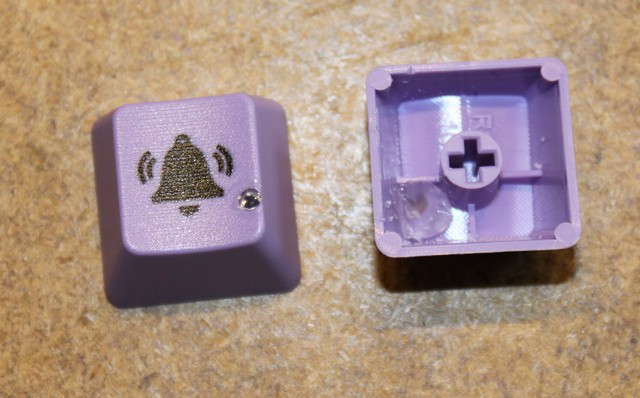
Prior to my order, I experimented with some of my leftover blue keycaps from the Nixie Calculator project. I found that a blue LED behind a blue keycap illuminates about a quarter of the keycap in a sold of aesthetically-unpleasing manner. However, I could spray paint the underside of the keycap with black spraypaint, and drill a little hole for an indicator, and then squirt some holt melt glue in the keycap. This produced a pretty nice result — unless you look real close you can’t tell these aren’t factory keycaps with built-in indicator windows.
WASD Keyboards had the blue keycaps on backorder, so I ordered purple instead. This turned out to be very fortunate — the Purple Keycaps fully masked the blue LED, so I didn’t have to spray paint the backsides of the keycaps. Here’s a closeup of a keycap with the drilled hole and the hot blob of hot melt glue:
I made two keypads, for a total of 16 keys.
Acrylic Faceplate
The black acrylic came from ponoko, like all of my other projects. I drew it up using inkscape.
Wiring
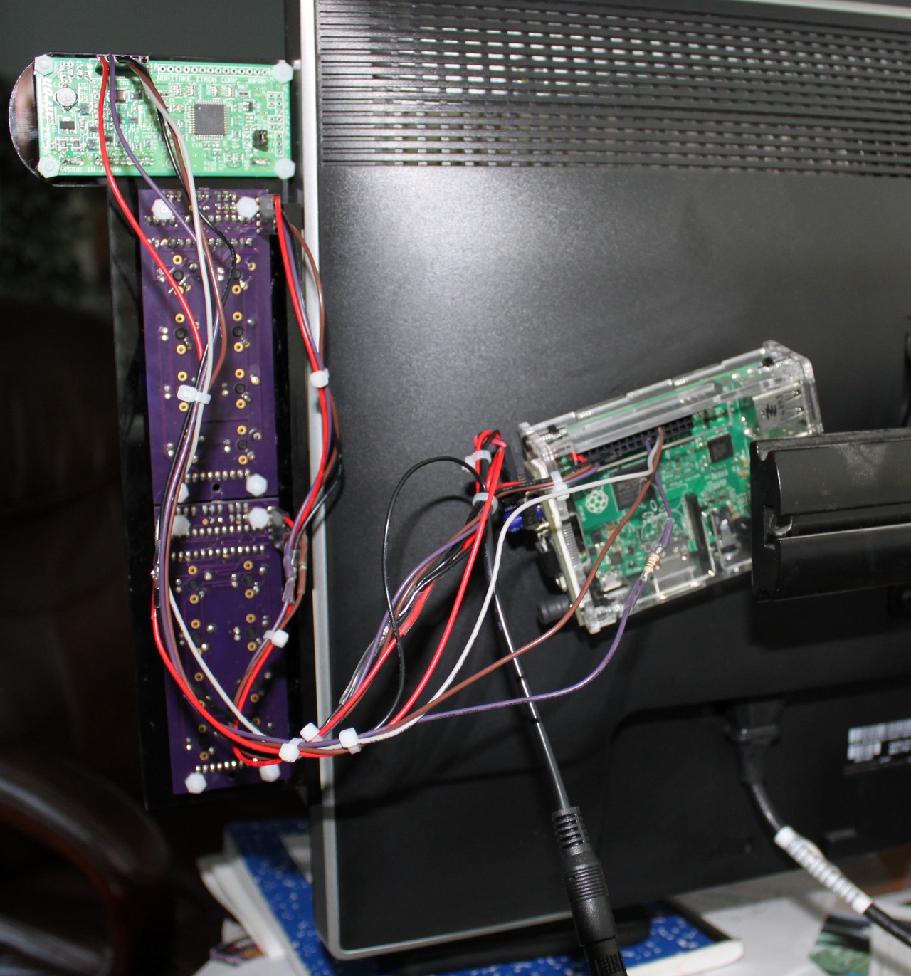
Here’s a view from the back showing the ratsnest of wiring:
Okay, so above you can see the VFD and the two keypads on the left, and the raspberry pi in an adafruit case on the right. The wiring is simple enough that I’m not going to draw up a schematic. The VFD, the Keypads, and the Pi are all powered from the same 5VDC source. The keypads connect to the pi’s I2C port, and the VFD connects to the pi’s SPI port. See my article on the VFD for more info on VFD connection info.
For power, I used a custom built 5V switching power supply based on a LM2576, so I can power this from the same 12VDC supply that I use to run my other home built devices . I plan a separate article on the switching power supply later — you can buy similar prebuilt switching modules on ebay, for about as cheap as you can build them.
Software
The software is checked into git at https://github.com/sbelectronics/pi-controller


