
In this blog post, I restore a Teleram 4000, a portable vintage computer from 1983 that ran CP/M and used Magnetic Bubble Memory.
Motivation
Anyone who has read this blog a few times knows my fascination with computers that used magnetic bubble memory. The technology was only in use for a few years, and the computers that used it were fairly rare. The Grid Compass is a prime example, and another computer that I have restored. I previously restored a Teleram Portabubble, which is a much larger computer with a CRT screen. The Teleram 4000 is more of a notebook-sized portable, similar to a TRS-80 Model 100 in size.
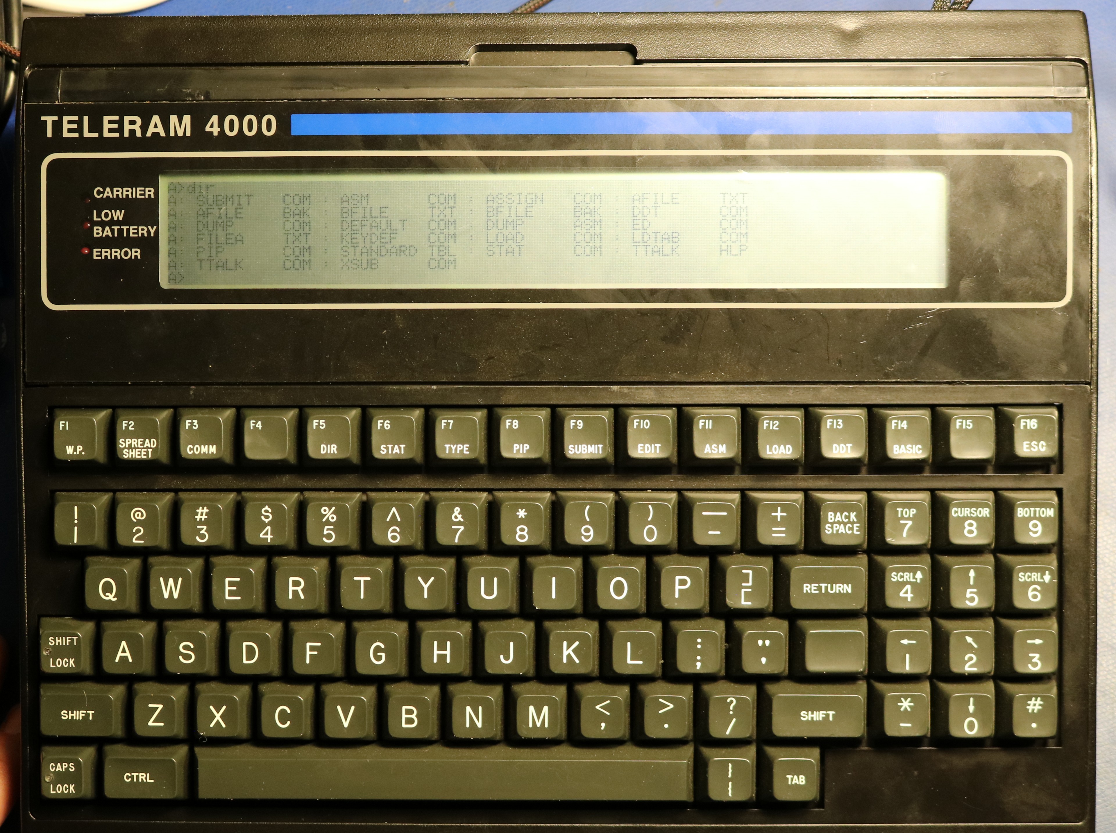
Teleram created two computers in the series, the T-3000 and the T-4000. As far as I can tell, the primary difference is that the 4000 offered an 8-line display whereas the 3000 only offered a 4-line display. Both computers featured 64KB of RAM, a Z80L CPU, and either 128 KB or 256 KB of bubble memory. The computer has a serial port, and typically would come with a built-in terminal program.
Teardown
The batteries were undoubtedly shot and the charging voltage is unknown and undocumented, so I decided to tear it down before powering it up. First, I removed the case top:
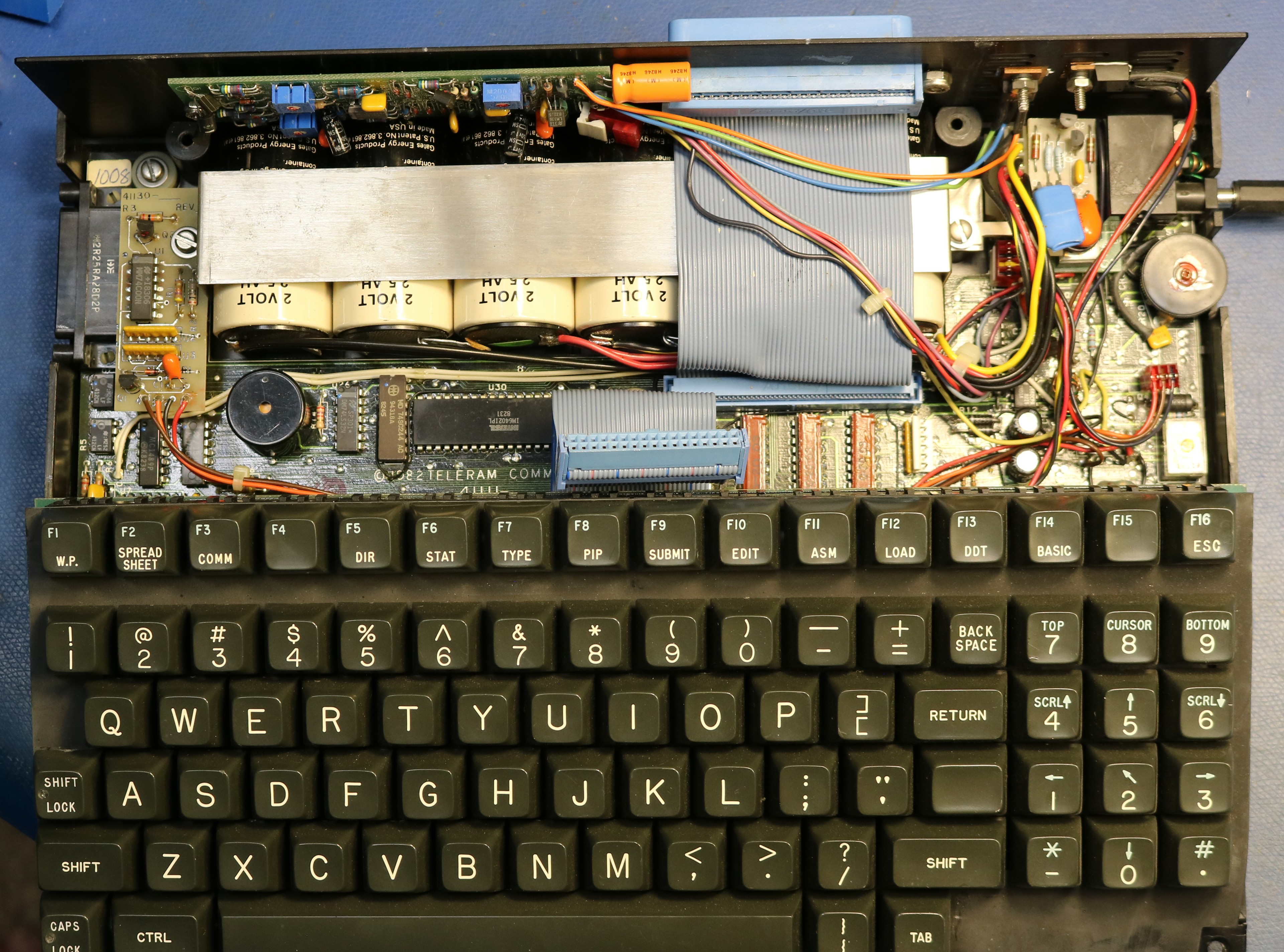
We can’t see the bubble memory or the CPU because they’re under the keyboard, but we can see several lead acid batteries. The cells are 2V / 2.5 AH. There are a total of 6 cells configured as two packs. Here are a couple more pictures:
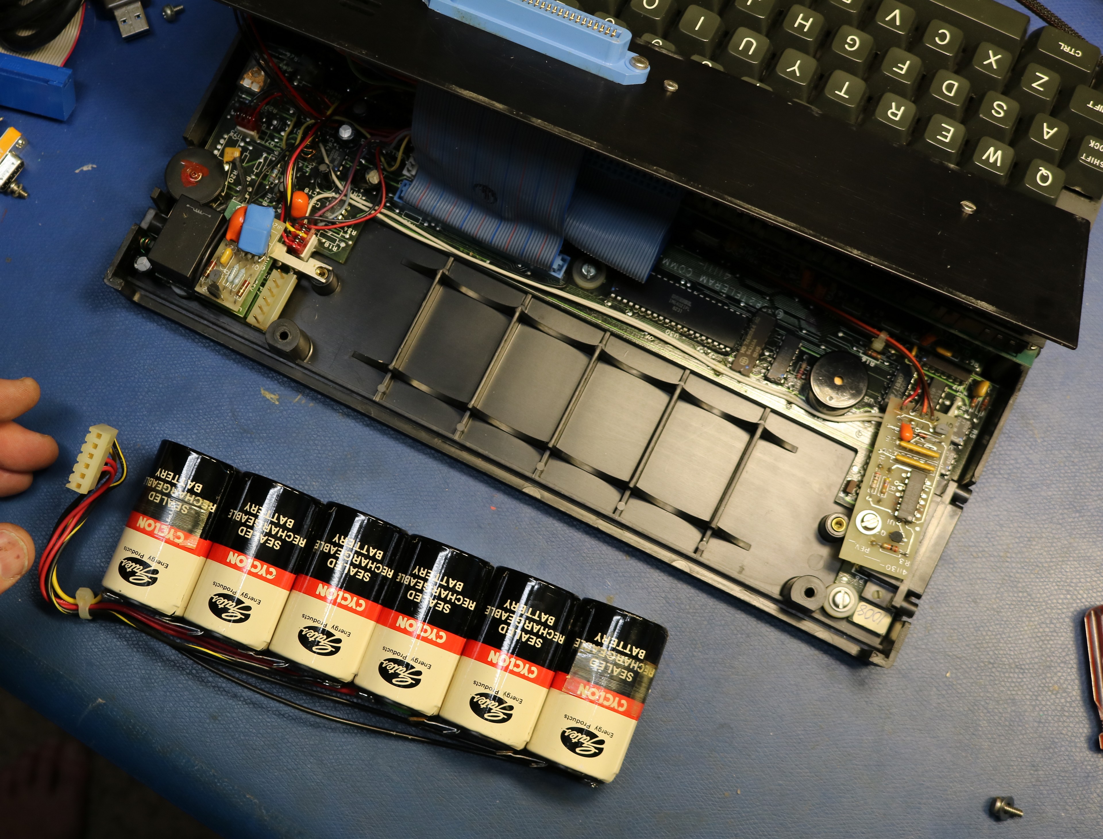
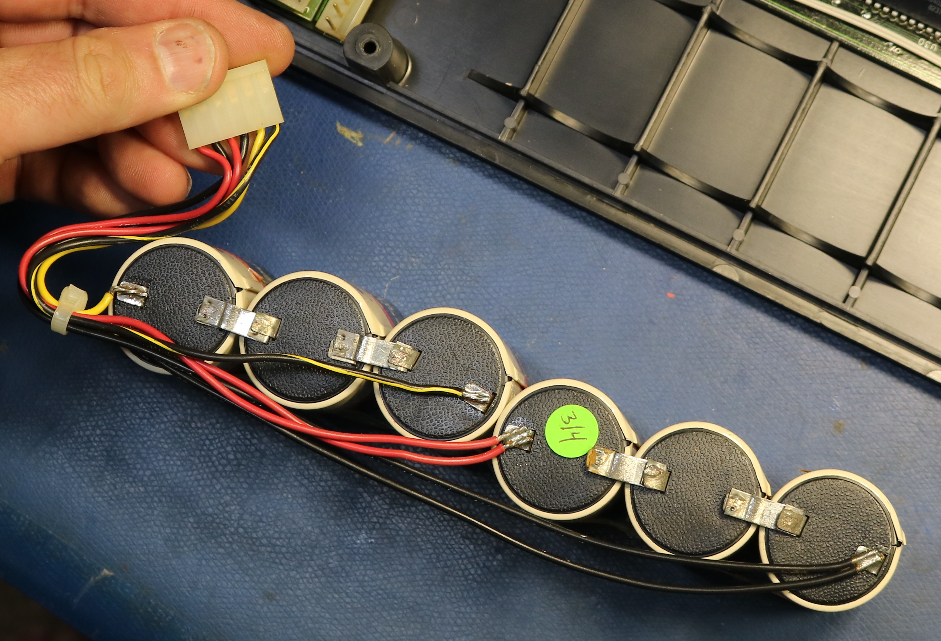
After removing the batteries, I removed the keyboard, and we can get a look at the bubble board:
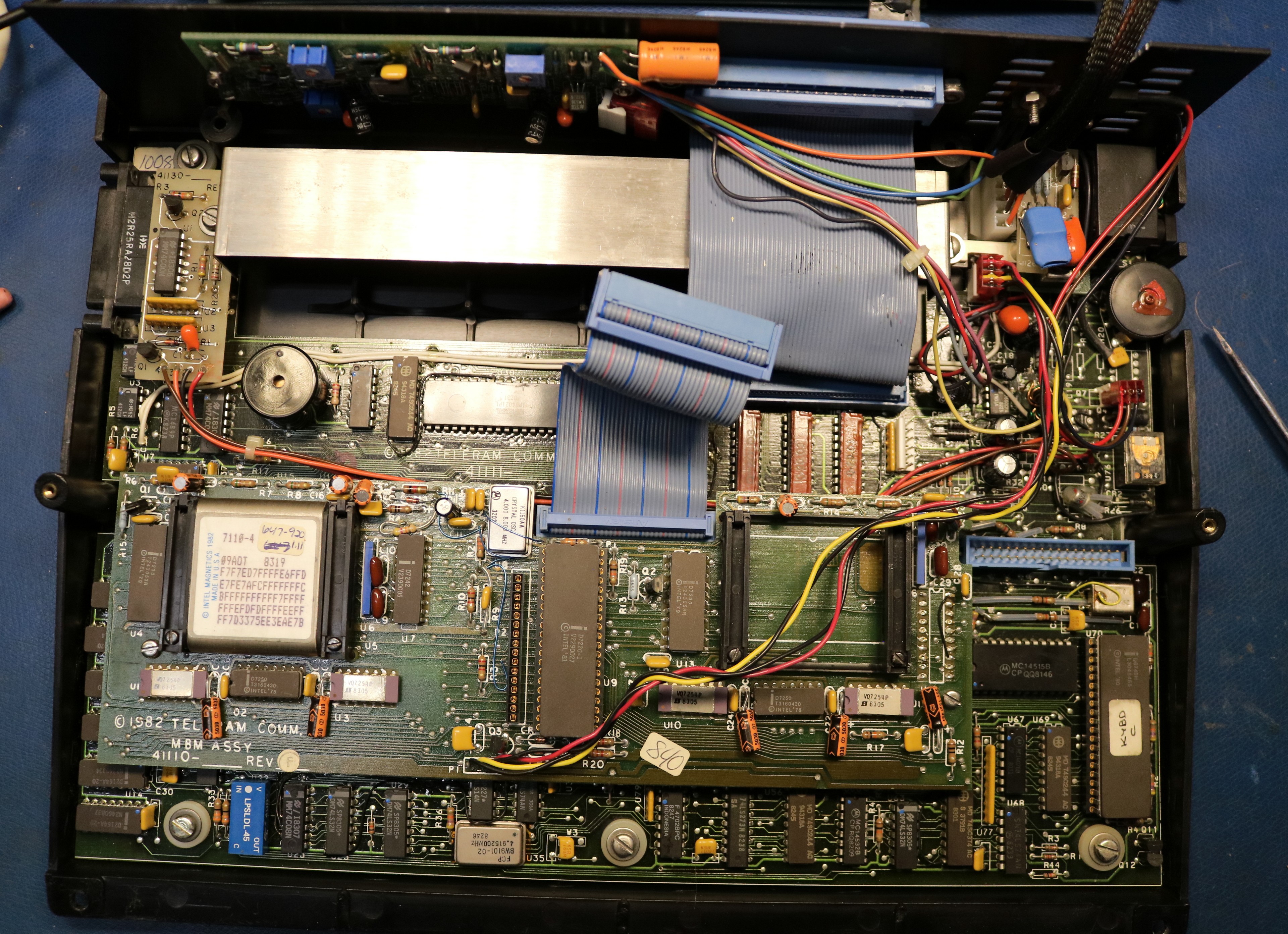
I removed the bubble memory board and took a closer look:
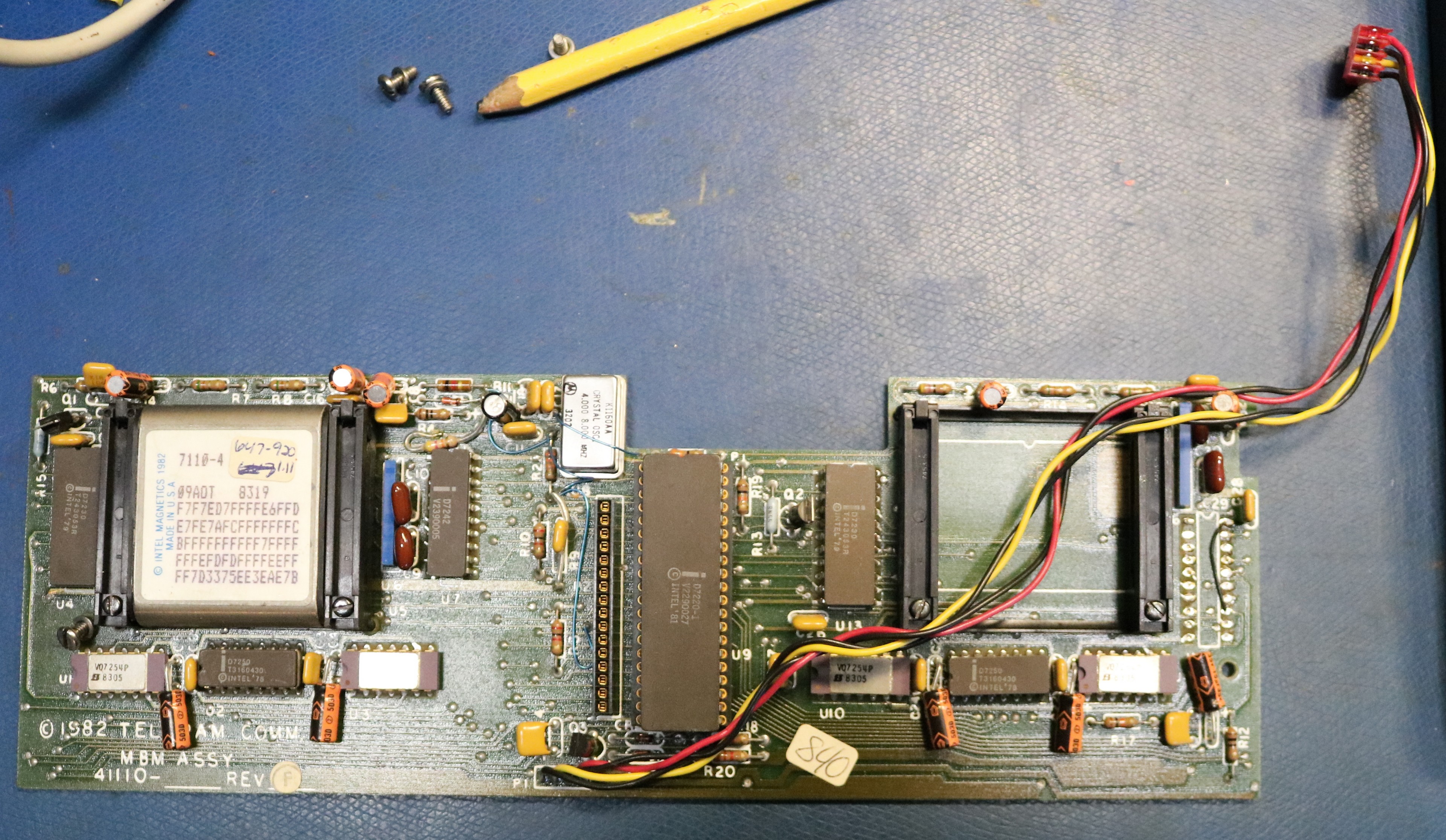
The bubble memory is an intel 7110-4 along with the 7220 chipset, a very common bubble memory subsystem for the day. Interestingly, there is a second socket, along with drivers for a second bubble memory. It would be relatively easy to add a second memory device and extend the capacity to 256 KB. The only wrinkle would be the need to format the new bubble memory and write an operating system image to it. The bubble memories do not work as independent devices; I think their data in this configuration would be interleaved.
Under the bubble memory board, we can finally see the main board:
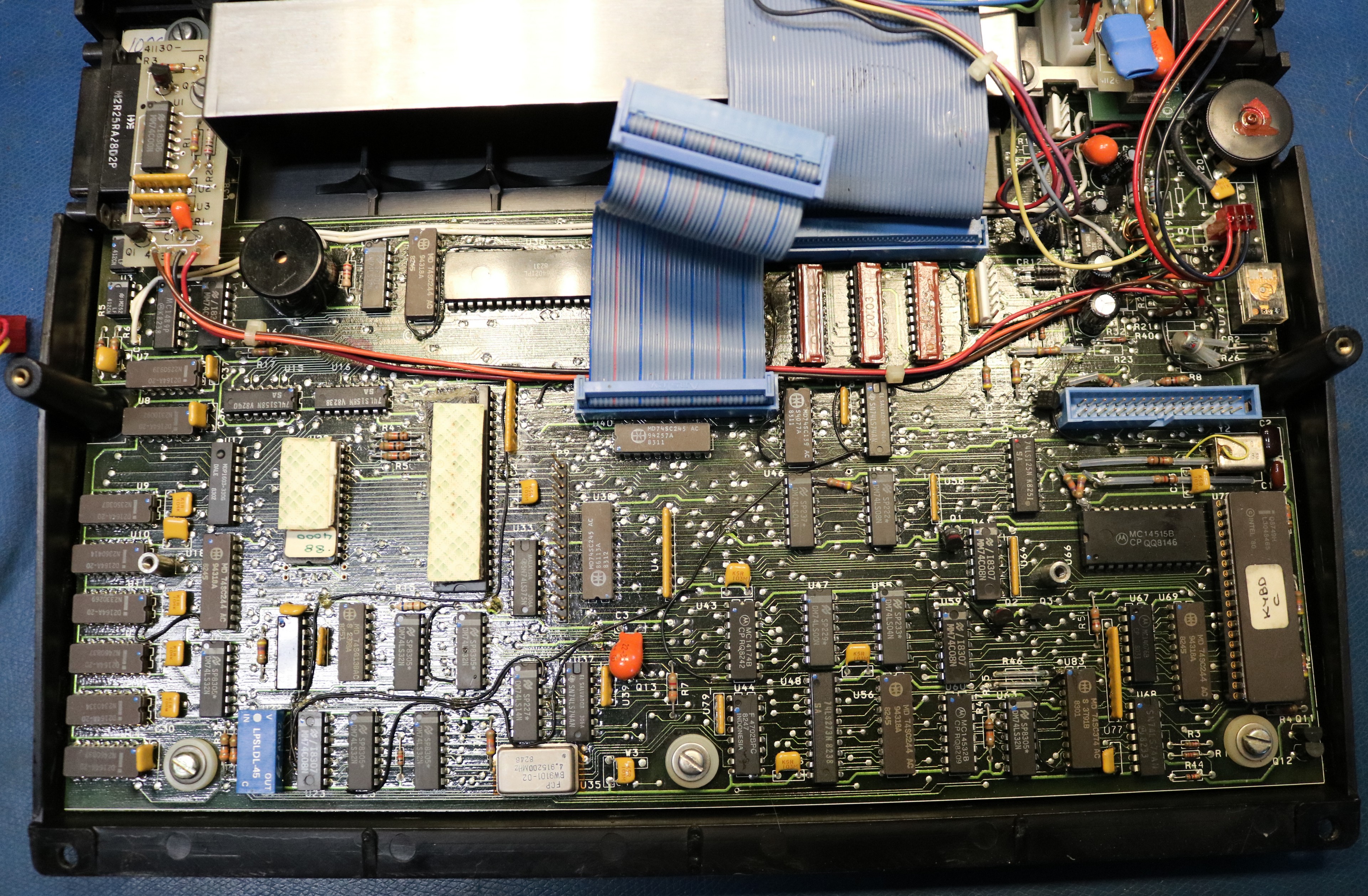
There are two ICs that are obscured by double-face tape. They are a 27C32 EPROM that holds the bootstrap and a Z80L microprocessor. There’s also 64KB of DRAM, a keyboard controller, and a bunch of traditional logic. All together, it’s relatively simple.
Bypassing the batteries
The battery configuration is interesting. There are two independent banks that are a nominal 6V each. These banks are connected in parallel most of the time. However, when the bubble memory is accessed, they are switched in series to provide the 12V supply to the bubble memory. After a short time delay, they switch back to parallel. This creates a bit of complication. We can’t simply power the computer with a +12V supply, because the 6V supply is actually used to power the main logic. My best solution was to power the computer by wiring up two independent power supplies to the battery connectors.
Each supply I powered with +6.2V with a 1.4 A current limit. Make sure to use independent supplies with no common ground, otherwise you’d be up for a rude surprise when they were put into series. My tests showed the computer consumed up to about 1.4A on the 6 volt supply (across both packs, when in parallel). When it switched into series mode, it would typically pull 100ma from the second pack.
It runs CP/M
The computer runs CP/M 2.2
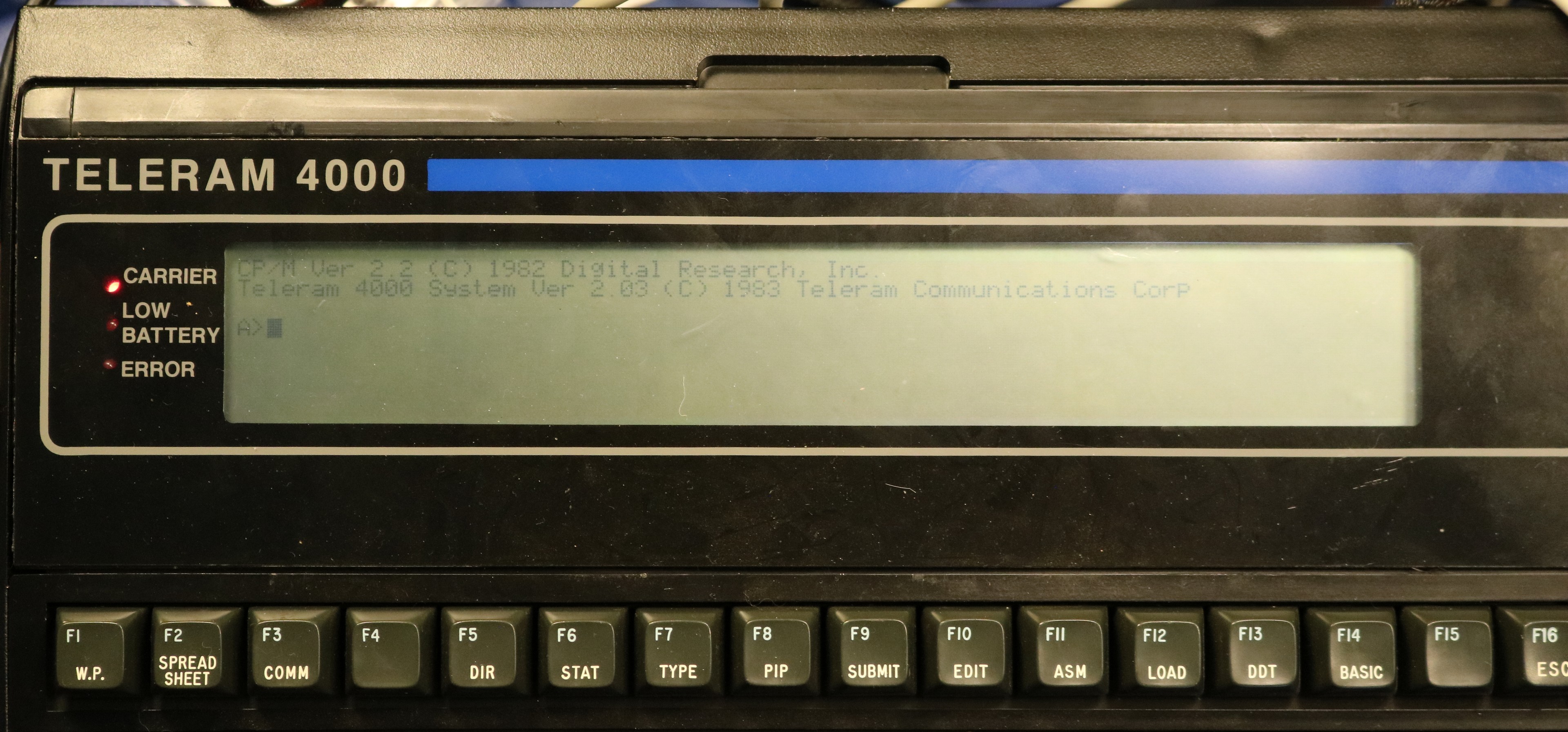
and there are a handful of programs present
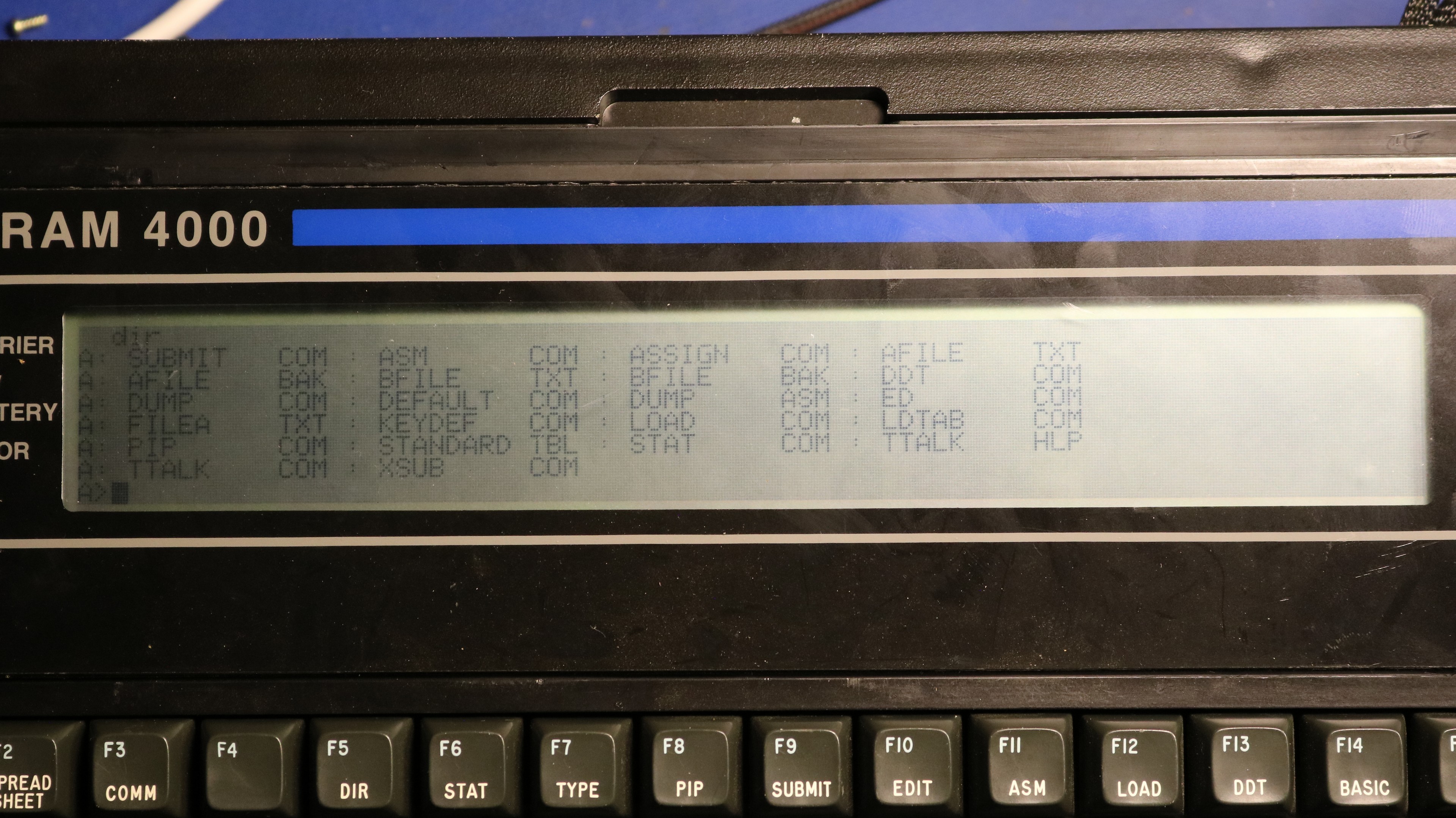
Most of the stuff here is standard CP/M stuff such as STAT, PIP, DDT, ED, etc. We have the assembler, ASM, and the loader, LOAD, as well. There are a few Teleram-specific programs such as TTALK and ASSIGN. TTALK is a terminal program that can be used to connect to external devices over the serial port. I used it in my demo video to interact with a Votrax Personal Speech System (PSS).
PIP may be easily used to transfer ASCII text by sending it to LST: or LPT:, or reading it from RDR: or PTR:. RDR: is by default assigned to the keyboard/LCD, so you’ll need to “STAT RDR:=PTR:” first to make RDR: use the serial port.
There’s also a CONFIG program that I think will allow you to configure some of the settings, including possibly the assignments for the devices like RDR:. The ASSIGN command also allows you to remap devices, in a more granular way than STAT.
My github repo contains disassemblies and reverse-engineered manpages for TTALK, ASSIGN, and a few of the other programs.
Dumping the Bubble and the Boot ROM
I was worried about the possibility of damaging the bubble by accident. With no external floppy drive and no Teleram corporation to send it in for repair, that would render the computer unusable. As such, one of my first goals was to dump the contents of the bubble memory.
I used Claude Code to write a Z80 assembly program to read all the sectors on the A: drive and print them in Intel Hex format out the serial port. I then captured them and converted them back to a 128KB binary image. This should be sufficient to restore a bubble memory if the need ever arises. The disk image is in my github repo.
I also made a copy of the 4 KB Boot ROM and I had Claude Code disassemble and comment the source code. The Boot ROM includes a full monitor that is triggered by NMI or by an unreadable bubble memory on boot. How you trigger the NMI yourself I don’t know — it might be as simple as a special key combination.
Adding BASIC
The disk image did not come with Microsoft Basic (MBASIC). In fact, there wasn’t even enough free space to hold it. I had to delete DUMP.ASM and the various text files (AFILE.TXT, FILEA.TXT, FILEB.TXT, etc) to make enough room. After that I reverse engineered the TTALK protocol, and I used TTALK to send the binary MBASIC.COM over to the computer. This allowed me to write basic programs and demo them in the video.
The reverse-engineered protocol and a python-based send/receive tool is included in my github repo.
Adding Batteries
I couldn’t leave the portable computer permanently tethered to a power supply, it begged to have batteries reinstalled. Using replacement lead-acid batteries was out of the question as they are both expensive and have limited shelf life, especially when left discharged. They’re also prone to leak. Instead, I constructed myself a pair of LifePO4 battery packs:
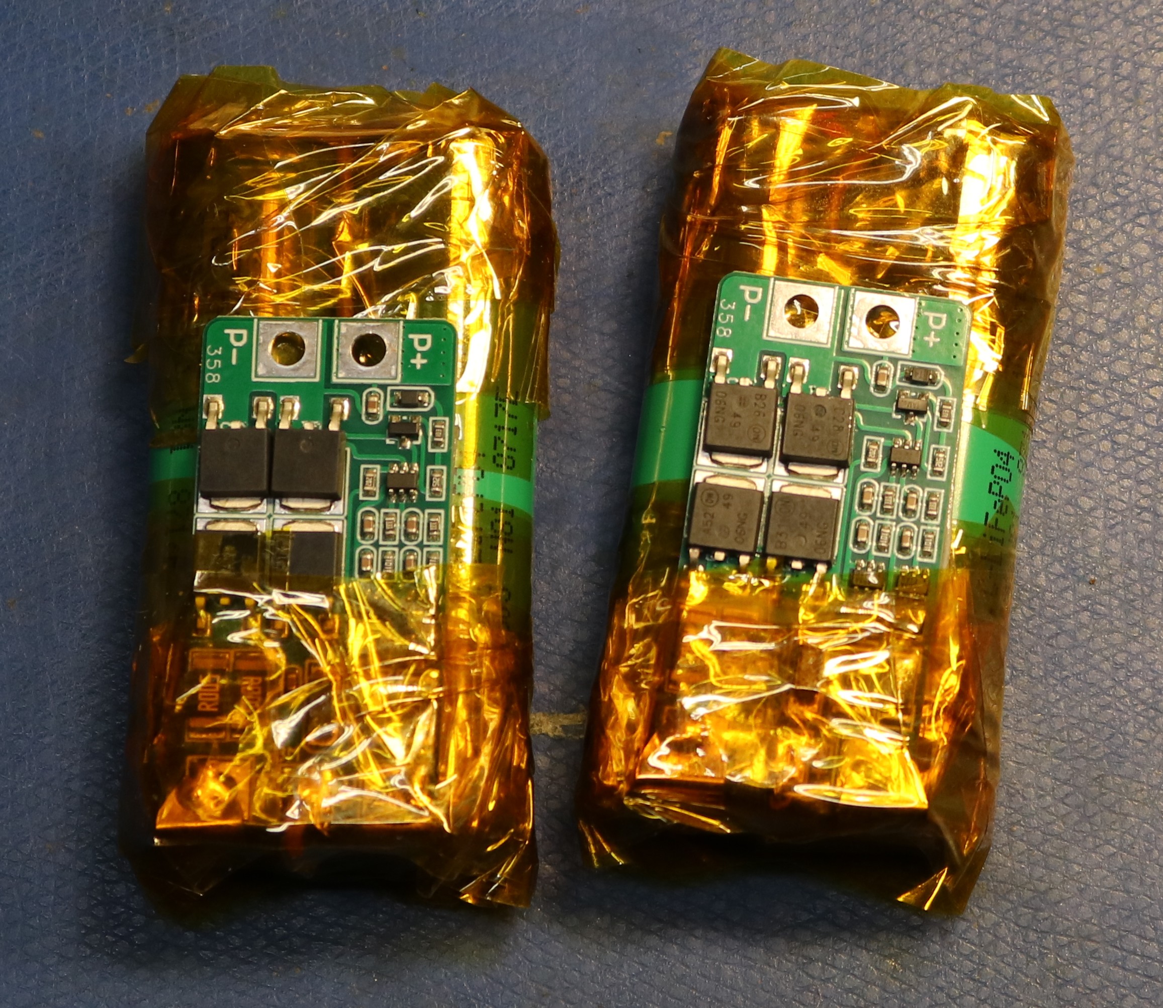
Each of these used a pair of 3.2V LiFePO4 cells together with a small BMS pack. That yields a nominal voltage of 6.4V per pack. This seems to work well, though charging them has left me with a little bit of caution. Normally you would charge these at approximately 7.3 V per pack (3.65V per cell). I’m not sure how much voltage the T-4000 was designed to take. There is some loss from the charging jack to the battery packs — I previously measured 9V at the charge jack to be 6.8 V at the cells. I’ve applied as high a voltage as 9.4V, which should in theory charge at approximately 7.2 V per pack. However, 9.2V makes me feel a bit safer. The one issue I’ve had is that they don’t charge very fast. At the 9.4V input I’m only seeing about 200 – 250ma of charge current. But it gets them topped off eventually.
Expanding the Bubble
One bubble only has 128 KB, and the CP/M distribution took almost this entire space! I was able to delete a few things and squeeze in Microsoft Basic, but with almost zero space leftover. The answer was to expand from one bubble to two:
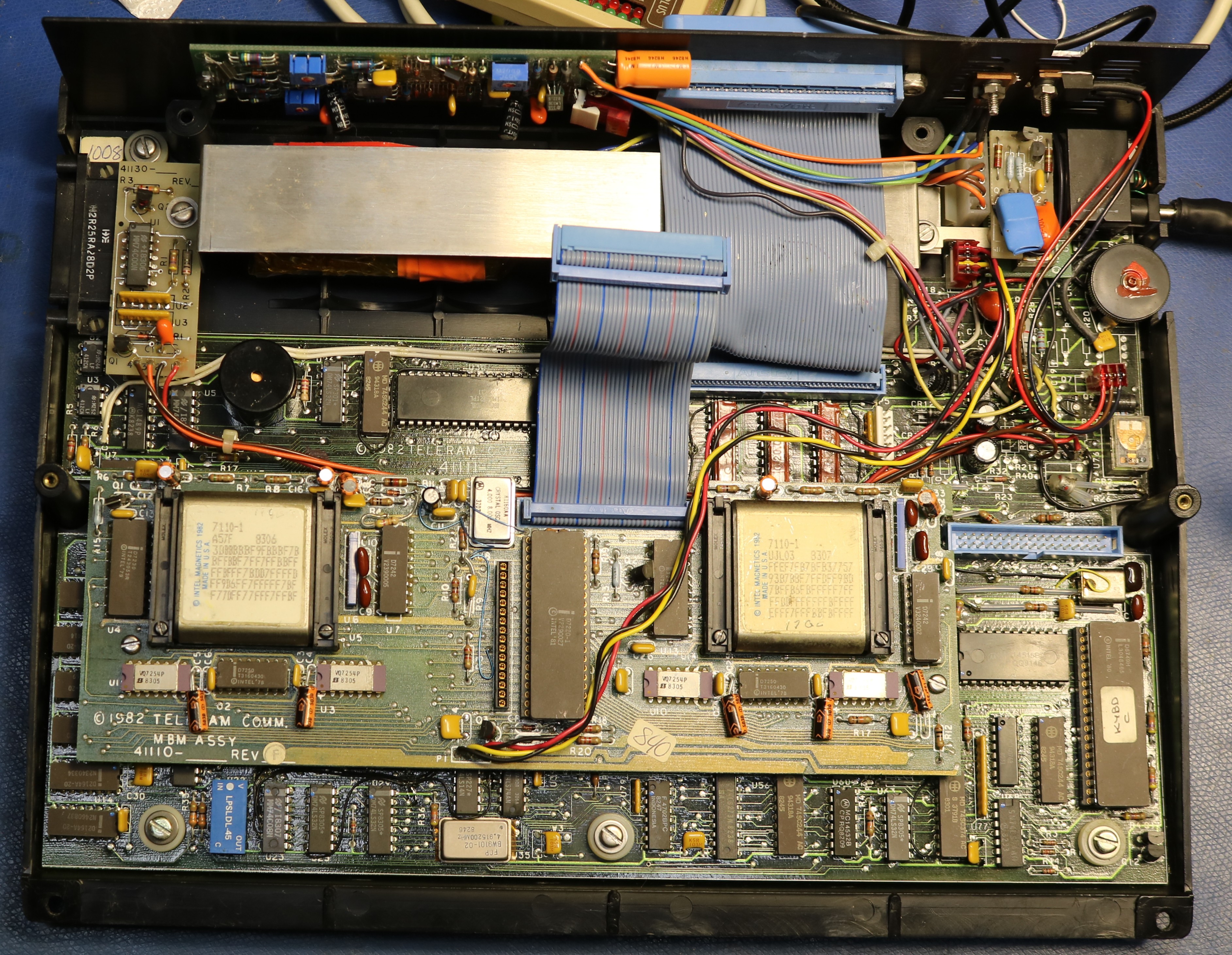
I was able to scavenge two spare 7110-1 bubbles from old PLC boards and install them. The other change that was needed is the footprint to the right of the rightmost bubble. If you look at the earlier pictures in this blog post, you can see there was a 20-pin footprint with a wire soldered from pin 13 to pin 20. This was a footprint for the second 7242, which was not used in a single-bubble configuration. Curiously, Teleram had apparently produced a 256 KB board, then manually removed the second bubble, manually removed the second 7242, and then added the bodge wire (which forces !enable low to the drivers for the second bubble). Enabling the second bubble was just a matter of reversing those changes. I scavenged the 7242 from the same PLC board I scavenged the 7110 bubble memories from.
Now, at this point, it might have just worked. The bubbles are addressed sequentilly, and the CP/M filesystem will automatically make use of the available space. However, I did not want to risk my original and only known-working bubble becoming corrupted, so my plan was to replace both bubbles and write a new CP/M image to it.
To do this, I patched the motherboard’s ROM with a serial loader that can be used to load programs into RAM. I used this to then load a bubble-writer program which was designed to receive bubble contents over serial, block-by-block, and write the blocks to the bubble. I then constructed a raspberry pi program to stream the replacement bubble. This took a few minutes at 9600 baud, but left me with a functional 256 KB filesystem. The process and the tools are in my github repo.
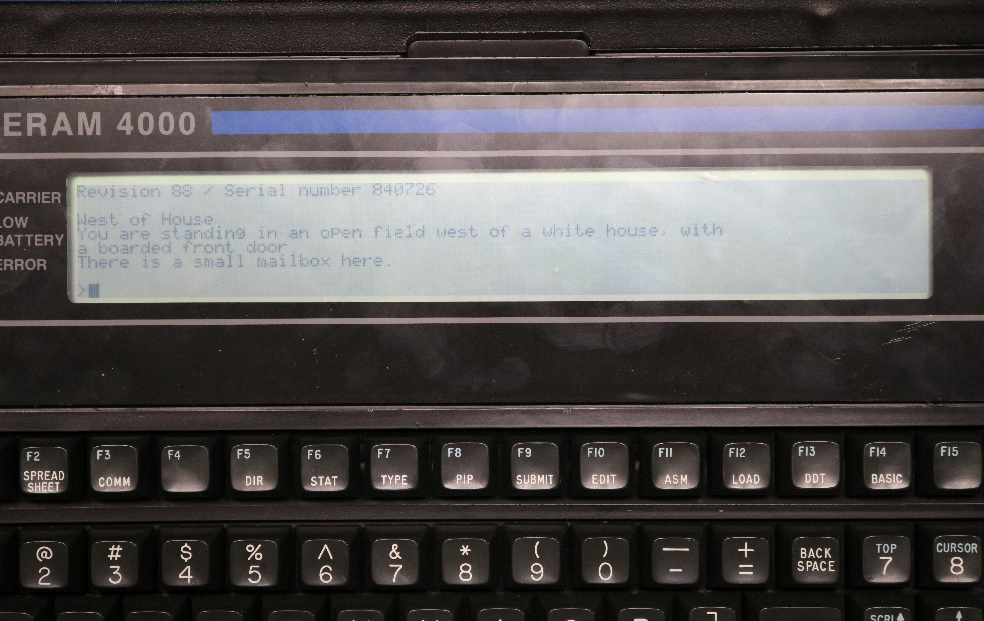
Finally, we can have Zork!
The double-bubble expansion was necessary for one huge important purpose — there wasn’t room enough on the single bubble for Zork. With 256 KB, there was now plenty of room. I copied Zork over via TTALK. Being a standard CP/M system, it had no issue playing Zork!
Teleram vs the TRS-80 Model 100
| Feature | Tandy / Radio ShackTRS-80 Model 1001983 | TeleramT-30001983 | TeleramT-40001983 |
|---|---|---|---|
| Released | April 26, 1983 | February 1983 | November 1983 |
| CPU | Intel 80C85 (CMOS)2.4 MHz | CMOS Z80 (Z80L) | CMOS Z80 (Z80L) |
| RAM | 8K – 32K | 64K | 64K |
| ROM | 32KOS + applications | 4K | 4K |
| Display | 8 × 40, text240×64 pixel graphics | 4 × 80, text only | 8 × 80, text only |
| Operating system | Proprietary ROM menu OS | CP/M | CP/M |
| Mass storage | Battery-backed CMOS RAMno internal disk | 128K bubble memoryexpandable to 256K · CP/M drive A | 128K bubble memoryexpandable to 256K · CP/M drive A |
| Bundled software | BASIC, TEXT, TELCOM, ADDRSS, SCHEDLin ROM | MBASIC, assembler, teleTalkno word processor | not documented |
| Modem | Built-in, 300 bauddirect-connect | Novation Cat (acoustic)external, included | not documented |
| Other I/O | RS-232, parallel, cassette, barcode, system bus | RS-232C, teleConnect bus | RS-232C, teleConnect bus |
| Battery | 4 × AA, ~20 hr+ internal NiCd memory backup | Sealed lead-acid pack | Sealed lead-acid pack |
| Price (1983) | ~$1,099 – $1,399 | $2,995 | not documented |
Display is the only confirmed difference between the T-3000 and T-4000 — the T-4000 doubles the line count to 8 while keeping the full 80-column width. CPU, memory, bubble storage, I/O, and battery are identical.
T-3000 date: introduced February 1983 (in development since May 1982); one contemporary review placed its market debut in mid-1982.
Model 100 price: ~$1,099 (8K) to $1,399 (24K) per Wikipedia; an entry price near $799 is also widely cited for launch.
T-4000: CPU, RAM, ROM, bubble storage, I/O, and battery confirmed identical to the T-3000 from hardware inspection. Bundled software, modem, weight, and price remain undocumented.
In short, the Teleram 3000 / 4000 are much more capable computers than the Model 100 series. However, the capability comes at a cost in both money and weight, and this led to dominance of the Model 100.
Conclusion
In conclusion, this is a really fun little CP/M computer if you can find one. The batteries are still available, albeit expensive, so it could probably be restored to true portable operation if you wanted to. It should be possible to expand the bubble memory, though it would take some effort to write a new OS image. Expanding the bubble memory would make it a lot more usable, probably provide sufficient room to load a few games (Zork!).
There is an external drive that I’d love to have, if anyone has one available. I would also love a copy of the technical manual. There’s an external bus connector that is not documented.
