Introduction
In this tutorial, I’m going to show how to interface a Dekatron tube to a Parallax Propeller microcontroller. This is similar technique to what I used in the Packetron-9000 project, although in that project I used mosfets. MPSA42 transistors are much cheaper and a lot easier to interface.
Circuit Description
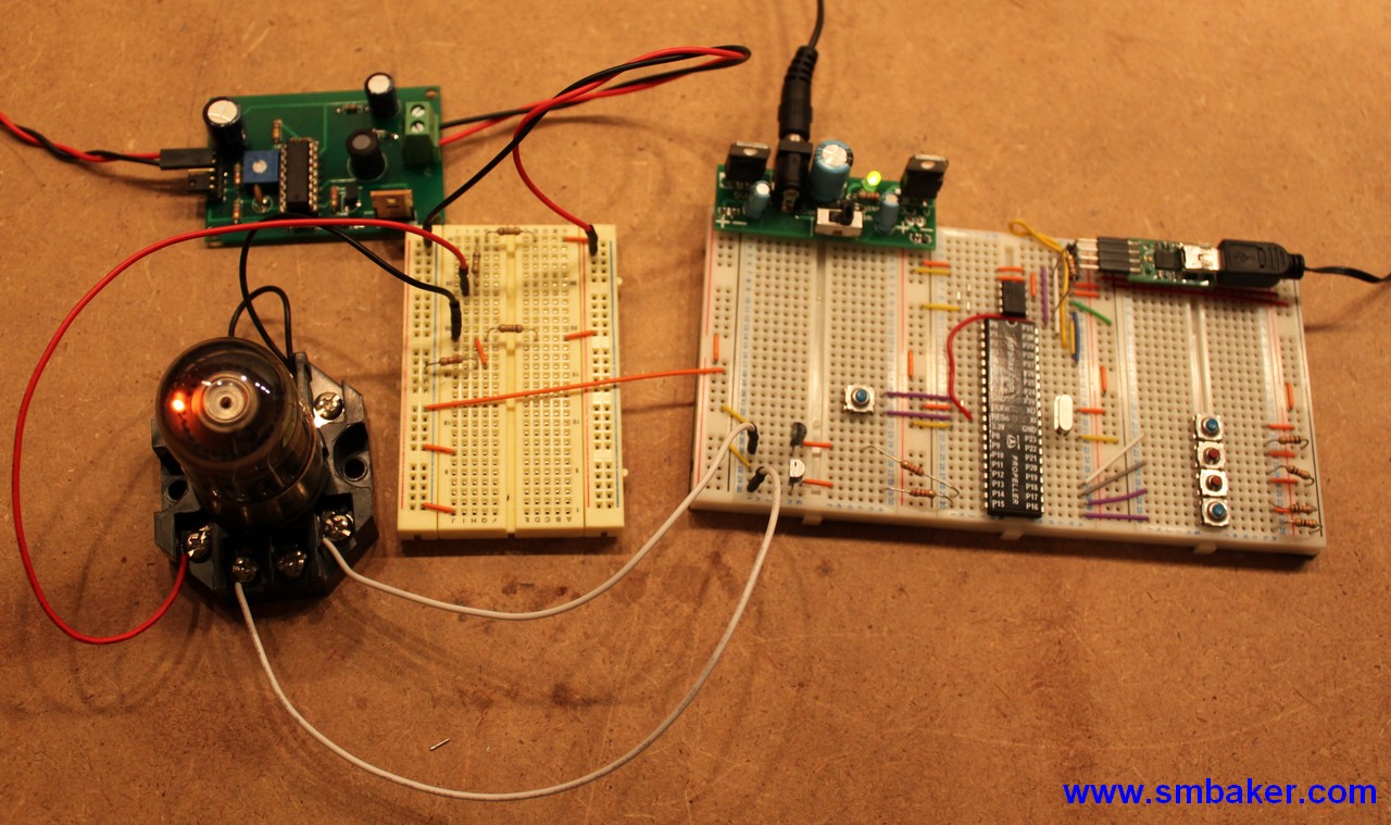
Above you can see several things. On the top left, we have the high voltage power supply described here. The power supply was modified by substituting a 5.6k resistor for R1 (the resistor between the pot and ground). This allowed me to get a bit of extra range out of the power supply since it takes about 425V to properly work the dekatron.
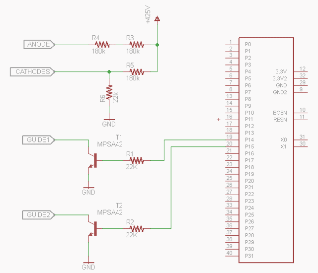
Below the power supply is a breadboard with a couple of current limiting resistors and a voltage divider. The voltage divider supplies (22/180)*425 = 52V that is used for the cathodes on the dekatron. The guides must be driven to at least 30 volts below the cathodes to make the dekatron count. -30V is hard to come by, but it’s much easier to just raise the cathode voltage a bit. 52V is close enough.
My original voltage divider used two 180K resistors for a total of 360K resistance on the anode. After experiencing a dekatron failure in a related project, I’ve raised the resistance to 1M. Better safe than sorry.
Below the voltage divider breadboard is of course, a dekatron tube. It’s a russian OG-4 dekatron tube, and is installed in a standard octal relay socket. These sockets are relatively cheap and easy to work with.
On the right, we have a propeller microcontroller from a propeller education kit. The Dekatron’s guide pins are operated using a pair of MPSA42 transistors. The emitter goes to ground, collector goes to the dekatron guide, and base is connected via a 22k resistor to the propeller’s IO pins.
Schematic
All of this is illustrated in the schematic below:
I’ve only illustrated the parts relevant to the dekatron interface — there’s some other mandatory propeller components like the eeprom, reset circuitry, crystal, etc that aren’t shown.
Program Listing
Below is the listing for the propeller program. It’s pretty simple, the guts of it are to pulse the two guide pins on and off. First, P1=On, P2=Off, P1=Off, P2=Off. Repeat that sequence over and over again and the dekatron will spin.
CON
  _clkmode = xtal1 + pll16x
  _xinfreq = 5_000_000

  GUIDE_MS = 10
  STEP_MS = 250
  P1=15
  P2=14

PUB main
  dekaSpinTest

PUB dekaSpinTest
  dira[P1] := 1
  dira[P2] := 1
  repeat
      outa[P1]:=1
      waitcnt(clkfreq/1000 * GUIDE_MS + cnt)
      outa[P2]:=1
      waitcnt(clkfreq/1000 * GUIDE_MS + cnt)
      outa[P1]:=0
      waitcnt(clkfreq/1000 * GUIDE_MS + cnt)
      outa[P2]:=0
      waitcnt(clkfreq/1000 * (GUIDE_MS + STEP_MS) + cnt)
Youtube Video
Finally, here is a youtube video that describes all of the above, and more!


I know I’m ten years late to the party, but this is great. Running the cathodes at 50 volts is brilliant. Still negative with respect to the anode, and all you half to do is ground the guides. Well done.