I’ve had a few requests for some information on the high voltage power supply that I’m using in some of the projects (in particular, the IN-13 nixie bargraph project). The design is based on the TubeHobby website (http://www.tubehobby.com/) and is the power supply used in their NC2.1 clock kits (http://tubehobby.com/show_det.php?det=42). I built this very kit as my first nixie tube project, and you can find a review of this excellent kit in the reviews section of my blog.
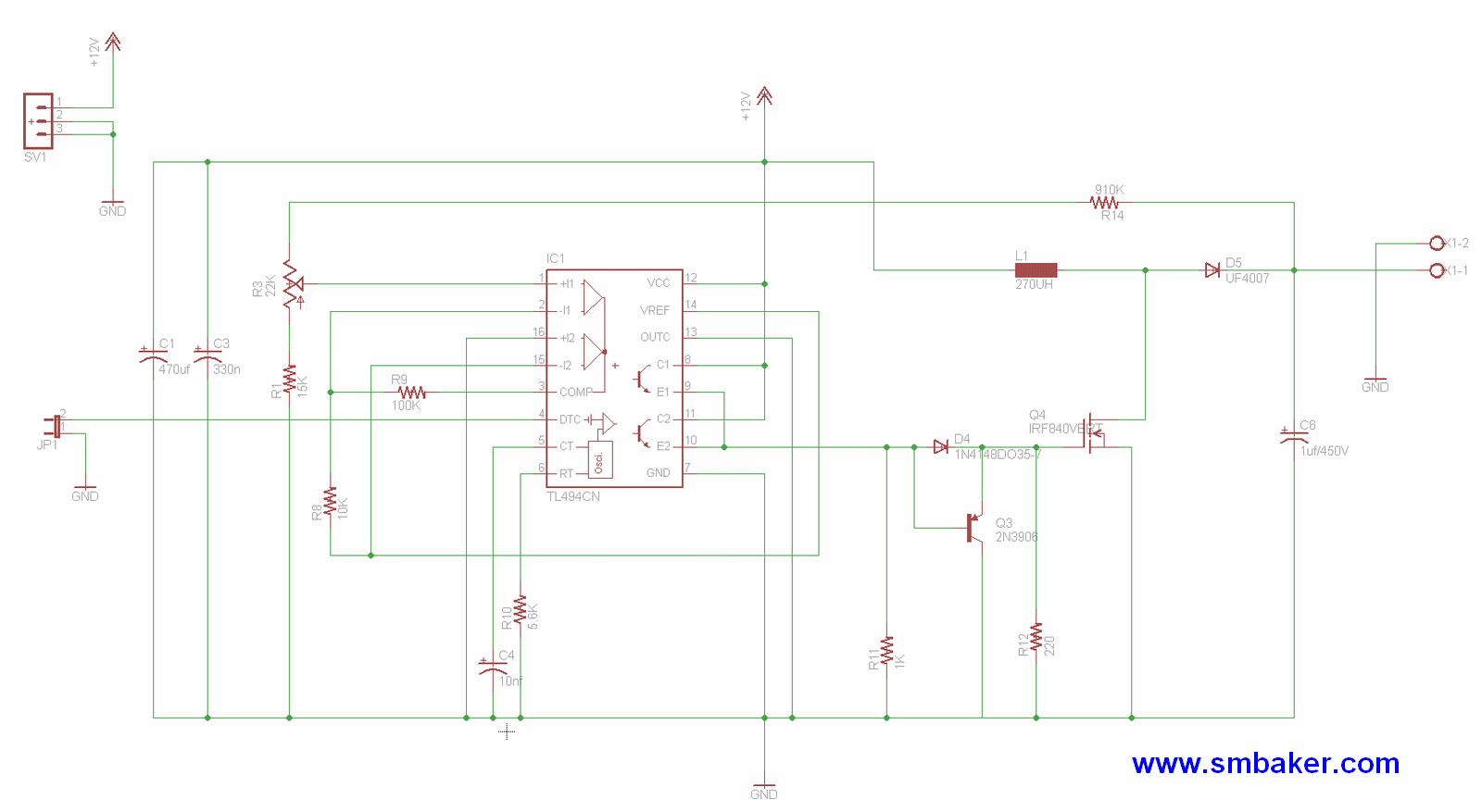
Anyhow, onward to the schematic: (click schematic for full-size view)
Click on the schematic for a full-size view.
The circuit is a switch-mode power supply based on the popular TL494. I recommend grabbing a dozen or more of these chips from your favorite supplier, as it’s also the chip used in my plasma speaker projects.
The voltage is controlled by the potentiometer, allowing a range of XX to YY (todo: measure this) with the default components. The original design used a 250V output capacitor, but after burning one of those out with a carelessly high voltage setting, I think it’s wise to have the extra leeway afforded by a 450V cap if you have one.
The jumper for deadtime should have a jumper installed to enable the supply.
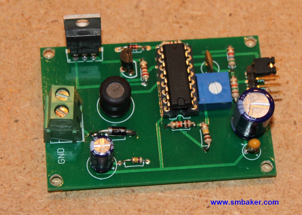
Below is a picture of the completed board:


Nice post!
Several questions though…
Could you guide me to scale the circuit to 0-120V at 5A for the output from 12V input?
The voltage isn’t too critical, but the current is.
Also, how did you make such nice PCB? Especially the silkscreen.
Thanks for your time!
I didn’t design the circuit, it came from tubehobby.com, so I’m not all that sure about modifying it. 5A is a lot of current and this is a low-current supply, so my guess is that it’d be difficult to scale it in that manner. The PCB was designed using Eagle and then fabbed by batchpcb.com — the prices at batchpcb are pretty good, but it can take several weeks to get completed boards. They always include silkscreen and solder mask.
Wow, thanks for the super quick reply!
Yeah, that tons of amps on 12v supply…
Thanks for the info regarding the pcb.
Scott! I finally assembled my nixie psu board, totally based on your work. Ive took some readings and would like to share with you. Maybe you can help me improving the efficiency on my board. I did not have components with the same values as yours and I just used what I had. Got 28kHz no load working frequency and 60% efficiency with 6mA load. I have the scope shots available at http://tobiasmugge.wordpress.com/projetos/nixie-psu/
Great work you are doing! Just saw the new amplifier you built.. amazing!
Hello
I am interested in using the TL949 chip as im designing a tube footpedal for guitars but need to keep switching noise very low as there is a lot of gain in the pedal design used for guitar distortion etc etc. I have used other small nixie tube supplys and whilst they do work they are noisey! Do you know what the noise levels are likely to be at around 200v region… 5mv, 10mv etc etc
Many thanks and sorry for the long winded question.
Simon
Awesome website yours, i wish to change my PCB components to be your above. My power supply working in 220Vac to 24Vdc, 12Vdc and 5Vdc. what time Chips can i use to change some of my power supply component. If you have some schematice please let me show it. i do appreciated to you. thank