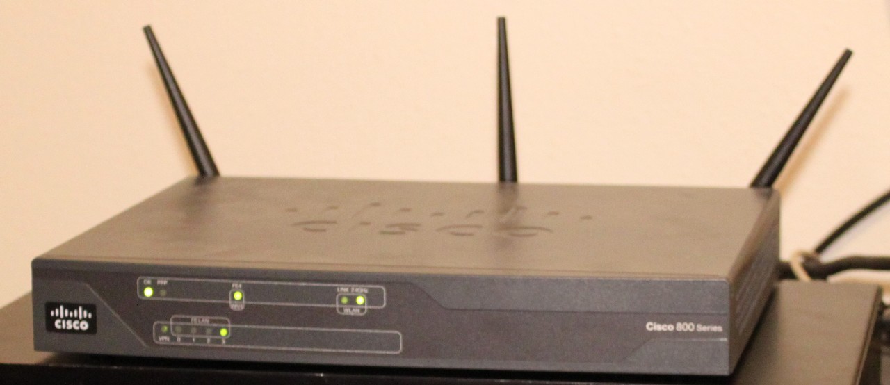
My cisco router is nice… but it really doesn’t tell me at a glance how much network traffic there is. It just has a LED. Does a LED indicate a packet? ten packets? a thousand packets? a million packets?
Clearly, something better is needed.
We need an indicator that one can tell at a glance exactly how much traffic is coming or going from the Internet.
We need 1960s vacuum tube technology.
We need dekatrons.
Thus, I give you: The Packetron 9000.
Four Soviet OG-4 Dekatron Tubes. Shipped to me from Odessa, Ukraine.
One Parallax Propeller microcontroller with ENC28J60 ethernet interface.
FOUR HUNDRED and TWENTY FIVE volts of pure DC power.
Mosfets, 8 of them, they’re not even supposed to work at 3.3V.
This device requires a youtube video to demonstrate its full potential.
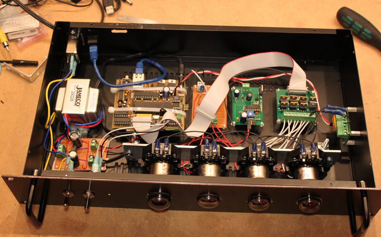
Here’s a view of the internal components of the Packetron 9000:
The nice thing about this project is that almost everything was a surplus design from one of my other projects. In order from left to right, we have:
- Transformer and rectifier board. The transformer is a 12.6v center tapped. I full-wave rectified the 12V to use as a power source for the high voltage power supply, and then pulled off the center tap for powering the logic board. For reasons I’ll never understand (I’m sure it has to do with RMS voltage and calculus), this yielded around 18V and 8.6V.
- Logic Board. It’s a parallax propeller microcontroller with a ENC28J60 for ethernet. The nice thing about the prop is its multicore design. Two “cogs” operate the ethernet, two operate the dekatrons, two run an optional video out for debugging, and a remaining cog operates as a central controller. The Logic board is a leftover from my NTP clock project.
- Voltage divider and current limiter Board. The dekatrons need 300-500 ua or so of current. This little perfboard uses some current limiting resistors (I think I used a pair of 180 ohm resistors per dekatron, that’s probably a bit too much current). Experience a dekatron failure with only 360k resistance per anode, so I upped the resistance to 1M per anode. The current limiting resistors supply the anode power to the dekatrons. A voltage divider is used to derive about 30-60 volts DC for the cathodes. Technically the datasheets tell you to run the guides at -30 to -60 volts, but we can run the cathodes at +30 to +60 and the guides at zero and nobody will be the wiser. It’s all relative.
- High voltage power supply. It’s the standard power supply detailed elsewhere in my blog. I had to tweak the resistors a little bit to set a higher output voltage of 425 volts. Also made sure the capacitor is suitably rated at 450 volts. I’d have preferred an even higher rated capacitor for safety, but 450v was the largest I could find.
- Driver board. Each OG-4 dekatron has two guide pins. These pins need to be pulsed in a specific sequence to cause the dekatron to count. I used IRF840 mosfets to do this. This presents a problem as the IRF840 does not drive reliably from 3.3 volt logic. I had two different brands of mosfet. The “made in china” ones entered a linear state driving the guide pins to approximately 56 volts (open state was measured at about 132 volts). The “made somwhere else” ones behaved normally, driving the guide pins to zero volts. The china ones had to be cut out of the circuit and replaced. Choosing something else (MPSA42 transistors would probably suffice, or alternatively choose a logic-level mosfet) would be a good idea. New board to try out MPSA42s are already on order from batchpcb.
- Relay board. If we simply turn the dekatrons on with all cathodes connected, then they’ll start up in some random state. The dekatrons have two pins for cathodes — Cathode_zero and Cathode_1_to_9. So, we can boot it up with only cathode zero connected. This ensures all dekatrons start pointed straight up. Then we kick on the relay and apply cathodes 1 to 9. Since cathode zero is already lit, activating the others won’t alter the state. This lets us bootstrap the cathodes in a known state.
So, how does this all work? The control module is implemented in a cog and does the following:
- The propeller sends a constant stream of SNMP requests to my cisco router. These requests are for four counters on the WAN interface: in-unicast, in-nonunicast, out-unicast, and out-nonunicast. The nonunicast packets I presume are broadcasts as they’re arriving on the WAN interface regardless of whether legitimate work is being done. I suspect they’re DHCP or something similar from the comcast network or the neighborhood. out-nonunicast is effectively zero, so I optimized it out.
- The in-unicast and in-nonunicast are summed to get the total number of incoming packets. The number of outgoing packets is simply out-unicast since out-nonunicast is zero.
- I keep a circular buffer that holds the timestamp and count of incoming and outgoing packets. There’s 5 slots in the buffer.
- Every time the buffer is updated, I compute the delta = (current_count – oldest_count), elapsed = (current_time – oldest_time) and rate = delta/elapsed. This creates a sort of average over 5 samples and smooths out a little bit of burstiness.
- Depending on the position of the selector switch, I feed either in_rate, out_rate or in_rate+out_rate to the dekatron module, so that the dekatrons will increment at that frequency.
The dekatron module is composed of two cogs:
- The first cog loops at a specific frequency (as determined by the parameter passed to it) and increments a counter. For example, if there are 1000 packets per second, then the frequency is set to 1000 Hz, and the counter will be incremented 1000 times per second. The prop can handle this loop in spin up to a few hundred thousand Hz which is plenty for our purposes.
- The second cog wakes up every 1 ms and looks at the counter, checking each digit. If the ones digit has changed, then the lowest dekatron is kicked over a tick. If the tens digit has changed, then the next-to-lowest dekatron is ticked. Ticking a dekatron involves a simple sequence of G1, G2, ~G2, ~G1. A hundred microseconds between transitions is more than sufficient. The OG-4 dekatrons are only good to a few kilohertz, and that’s the reason for this added bit of complication. By updating every 1000ms, we guarantee we are never spinning a dekatron faster than one kilohertz. The user won’t really be able to tell the difference. The higher order dekatrons preserve correctness in counting, so the most significant digits are accurate.
The remaining cogs serve some utility functions:
- CRT driver. The standard prop video out driver.
- Updater. Takes the current state and outputs it to the video driver, for debugging. This could probably be integrated into the main loop, but it is kinda slow and affects timing, so it was easy enough to push it off to another cog.
- Ethernet driver. Harrison Pham’s proptcp driver, with a good deal of customization. I stored four static SNMP request packets in it (in_unicast, in_nonunicast, out_unicast, out_nonunicast) and send them out via UDP. UDP packets are demultiplexed and SNMP counters are adjusted accordingly. Wrote the UDP checksum and header stuff myself, was kind of a pain to get it right (involved some tcpdump’ing to a linux box to see where I’d messed up the checksums). Also wrote the ARP stuff myself a few years ago, as it did not exist in the proptcp driver at that time. Probably should rewrite all of my code to make use of the newer proptcp stack.
- SPI driver. Part of the proptcp stack.


Comments (1)