Some projects are easy. This was not one of those projects.
It started when I read an article in the June 2014 issue of Nuts and Volts magazine. Seemed like a great idea — rather than spend a hundred fifty bucks on an RF signal generator for aligning my radios, I could just build one and learn something in the process.
I’m not going to be providing the full schematics for the RF generator that I built, because that would be intruding on the property rights of Nuts and Volts and the author of the article. I’ll show a few snippets of some of the modifications I made, but if you want to see the whole design or understand how it all works, I encourage you to buy the magazine. If I recall correctly, buying a subscription gets you electronic access to back issues. I’ve got some good ideas from Nuts & Volts over the years, there’s some good inspiration there.
Design Modification – Single Supply Op-Amp
The author’s RF generator used multiple transformers to deliver a variety of voltages. The case I had was a little bit small, and I decided I’d try to redesign the circuit to use only a single center-tapped 24 VAC transformer.
The first change I made was to use a common cathode varactor diode instead of a common anode varactor diode. Whereas the author of the N&V article needed to use a negative voltage to control his VCO, I could get by with a positive voltage to control mine. I settled on the MACOM 4ST079CK-287T varactor diode, mainly because there was some guy selling them on ebay, 15 of them for $10. The SMV1404-09 used in the N&V article, in contrast, is made out of unobtainium. As far as I can tell, they don’t exist (though I think the author may still have some stock).
Looking up the MA4ST079CK-287T datasheet reveals the parameters. The capacitance of the diode varies from 87.4pf at 1 volt to 11.8pf at 8 volts. It seems like I’m able to eek out a little more performance below one volt and above eight volts.
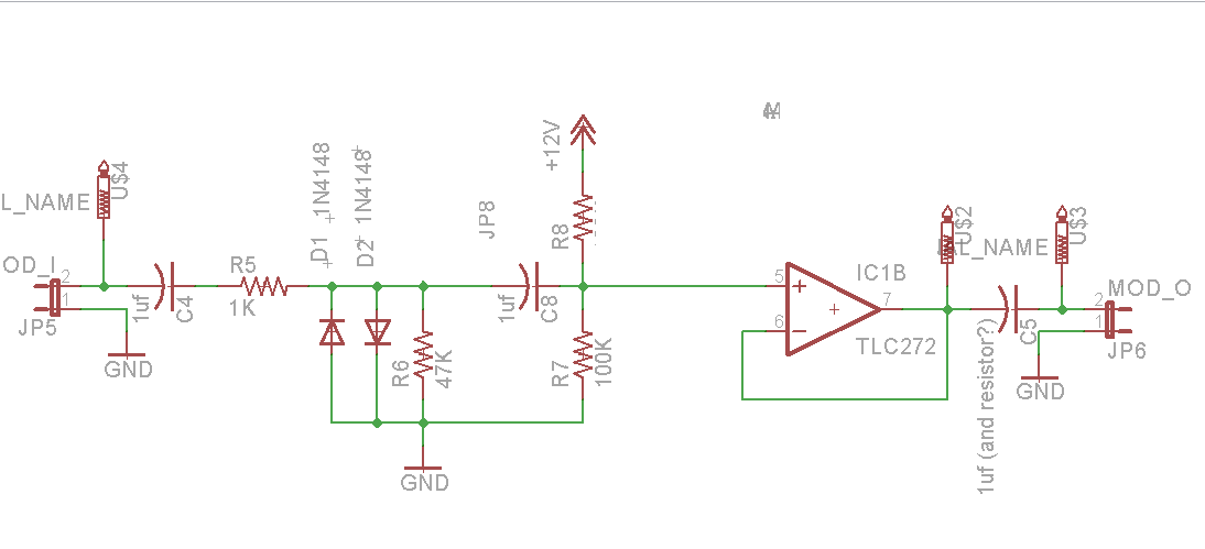
Okay, so using a common cathode diode allows us to bias our VCO with a positive voltage. That eliminates one of the needs for the dual-rail supply. The other need was for buffering the amplitude modulation (AM) signal. When I started this project, I didn’t know much about op-amps and AC decoupling. I knew my AM signal could go from – 0.7V to +0.7V, and I figured you wanna amplify a signal that can go negative, then you need an op-amp that can go negative. Not so! It suffices to use a voltage divider to pull the AC signal up into the range that a single-supply op-amp can handle. Let me illustrate with a schematic snippet:
The modification I made is the addition of R7, R8, and C8. The AM signal enters on JP5 and is AC coupled by C4. It’s clipped by diodes D1 and D2 to approximately 1.4 Vpp. C8 AC couples the signal again, and the voltage divider R7 and R8 will pull the signal to approximately 6V. My TLC272 op-amp is powered by 12V, so 6V is right in the center of the operating range. The signal is then AC coupled again by C5.
So what does this AC coupling do? An AC coupling capacitor allows an AC signal to pass through but blocks the DC component. So let’s say we have a 1 volt peak-to-peak sine wave that goes from – 0.5V to +0.5V. We pass that though a AC coupling capacitor to the R7/R8 voltage divider. We still have an AC signal that is 1 volt peak-to-peak, but instead of it going from -0.5V to +0.5V, it now goes from +5.5V to +6.5V. Perfect! That eliminates any need for the a dual-rail op-amp. We can power our TLC272 from a single 12V supply.
There’s a change not shown on the schematic above — I had to add a 100 ohm resistor immediately prior to the final decoupling capacitor, C5. Otherwise the TLC272 became too unstable.
I tried numerous op-amps in this circuit. LM358N seemed pretty noisy. TL072 does pretty well as a dual rail op-amp, but doesn’t work well as a single supply op-amp. TLC272 was the winner as it was less noisy than the LM358N while offering a single-supply design that can go almost all the down to ground. I have some TLC2272 on order, which are supposed to be even better.
Design modification – Power supply
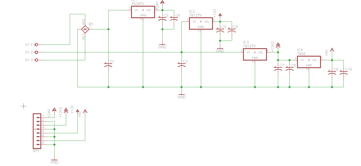
Now that we can get by with a single-source op-amp, I was able to modify the power supply design considerably:
As you can see, there’s nothing fancy going on with the power supply — it’s just your typical 78xx regulators. I did manage to drive it all from one single 24VAC center-tapped transformer. The reason why there’s two 12V supplies is that I wanted one clean supply for the op-amp, and a separate supply for the frequency counter module.
Sourcing components
This project required lots of components that I didn’t have.
- Inductors. You need lots of inductors for the main band switch. I ended up using 4,7mH, 2.2mH, 1mH, 680uH, 150uH, 47uH, 10uH, 2.2uH, and 330nH. The first 8 of these all came from one ebay seller in China. I ordered “20value 200pcs 0410 DIP Color Wheel Inductor” for nine bucks. Yeah that’s right 200 inductors for 9 bucks. It was quite a good deal and there’s a zillion inductors left over. the 330nH inductor came from digikey 70F337AP-RC-ND.
- Selector switch. You need a selector switch with at least 10 stops. They’re commonly available in 3, 4, 6, and 12. I ended up going with a “ALPS 2-Wafer 2-Pole 12-Position cycling Rotary Switch” from ebay. Jameco also sells a 12-position rotary switch, although it’s only a single pole and the author called for a double pole.
- The MC1648 VCO chip. Found ’em on ebay.
- Ferrite Beads. I ordered them from ebay, but that turned out to be stupid of me. The author called out the specific part numbers that you can get from digikey. I ended up ordering those anyway, as unknown composition ebay ferrite beads of bizarre size turned out to be not useful.
- GALI-55 amplifier. I bought ten of these on ebay for about twelve bucks. Mini-circuits (the manufacturer) was also kind enough to send me four free samples. You only need one, but in my incompetence I pretty much excelled at destroying them.
- 2-watt resistors for GALI bias. The author calls for a 392 ohm 2-watt resistor. I tried this, and it gets really really hot. I ended up going with two 840 ohm resistors in parallel instead. That’s a little off-spec and will reduce the power to the GALI slightly, but I found that it worked.
- LED frequency display. I bought “Blue-0-1-60MHz-20MHz-2-4GHz-RF-Signal-Frequency-Counter-Cymometer-Tester” on ebay. It cost me about $10 plus shipping.
You also need lots of small capacitors – 1uf, 0.1uf, 0.047uf, etc. I suggest getting an assortment off ebay. Go for the monolithic capacitor assortment. About ten bucks will get you enough capacitors to last a good long time. You’ll need other incidentals like resistors. You’ll also need some voltage regulators (7805, 7812, 7824). You’ll need some 10K linear pots. I’m assuming that everyone who is capable of building an RF generator is capable of finding common resistors and capacitors.
Keep in mind the parts from china will take a while to arrive, so order them well ahead of time, and order extras in case you wreck something.
Designing the circuit boards
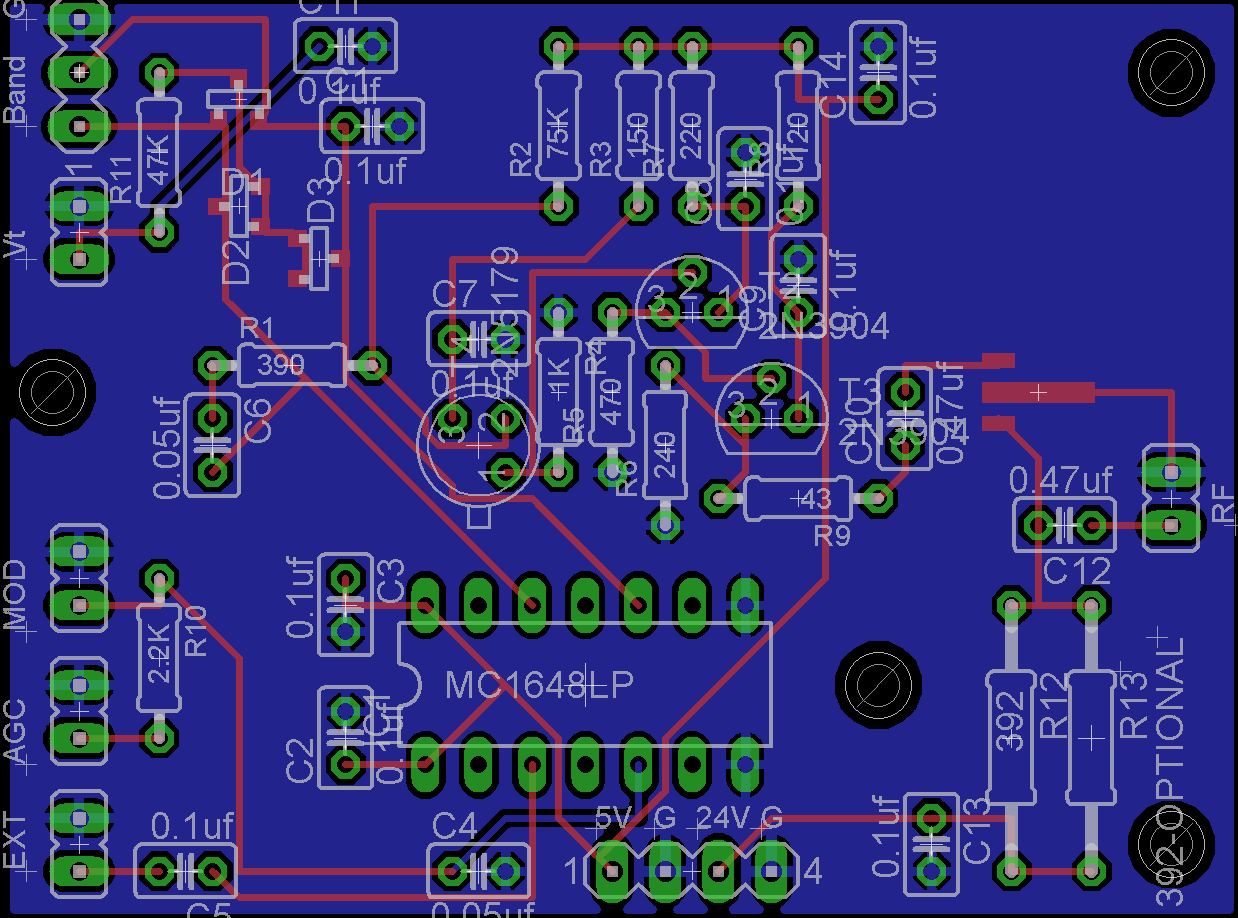
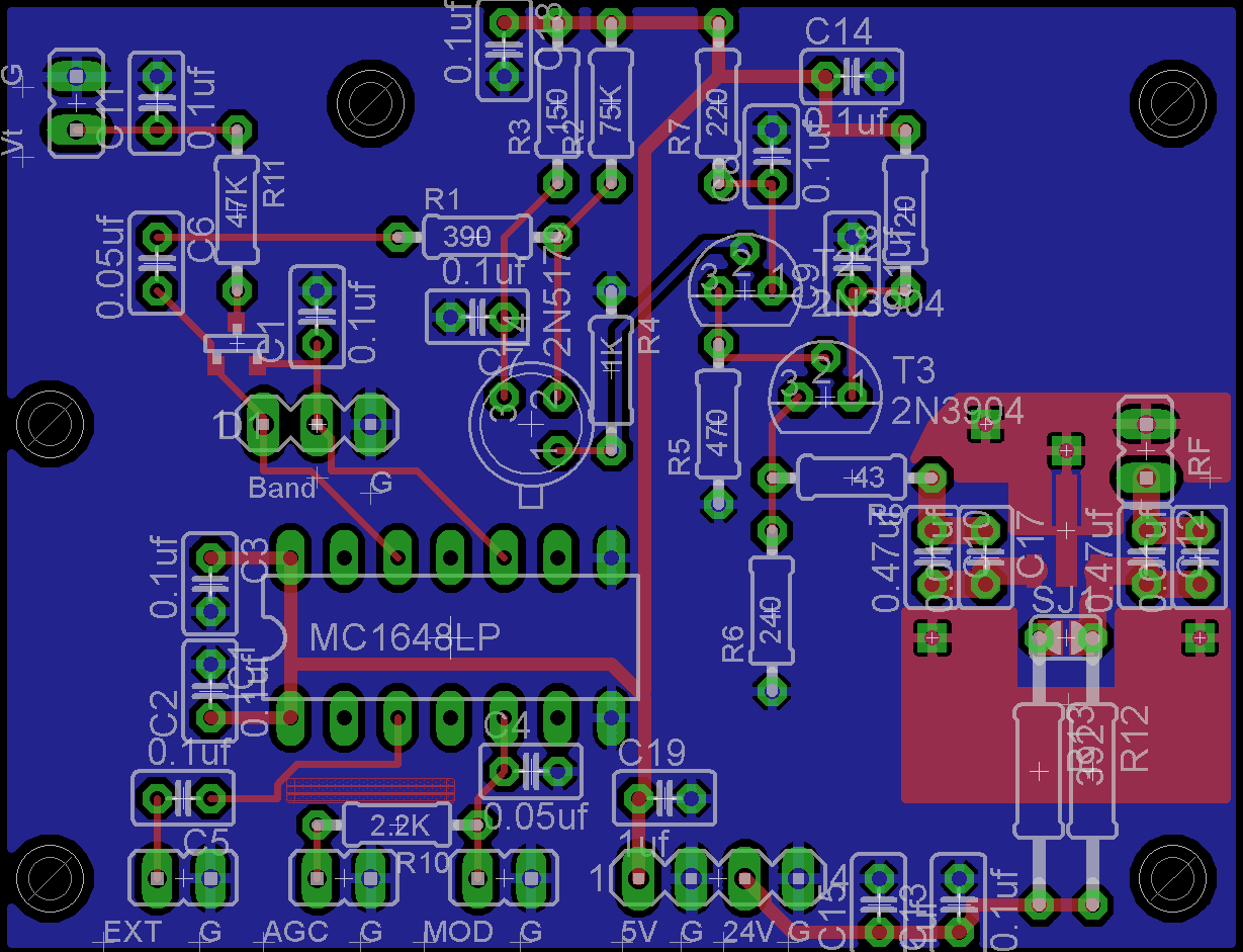
I like designing circuit boards, even if I am a noob who uses the eagle router. So I laid out this design:
That circuit board turned out to be really poor, an example of what not to do. In particular look at the long thin traces in the RF output section on the left hand side. The sharp right angles. The trace-to-nowhere when the optional R13 resistor isn’t installed. As we get into the ‘problems’ section we’ll talk about why those were bad.
Problem #1 – the voltage knobs didn’t work right
The design uses two pots for coarse and fine voltage settings. My RF generator was really weird — I could control the frequency up to about 80 Mhz, and then the knob started changing the frequency really really fast. Well, you recall how I said above that you needed “10K linear pots” ? You guessed it, I managed to solder in 10K logarithmic audio pots instead. I don’t even know where they came from; I could have swore I had never purchased audio pots. Fortunately, I also had some linear pots and this was a simple fix.
Problem #2 – there’s no gain
In my first video I conclude that everything is hunky dory because the external frequency counter showed the expected RF frequencies. Well, everything wasn’t hunky dory. To the contrary, it was all completely screwed up.
It turns out there was no gain at all from the GALI-55 amplifier. I was only getting a few hundred millivolts output on the RF jack. Checking the circuit, it was even loading down the signal from the transistor that fed it. Somehow that particular GALI had become damaged. There’s a whole separate blog post detailing my frustrations with the GALI-55 amplifier, mostly because I didn’t know what the hell I was doing when it came to building RF circuitry.
Making a long story short, what we (I enlisted the N&V article author’s help) think was happening was that my poor PCB layout was inducing a parasitic oscillation into the GALI-55. This chip is capable of oscillating will into the gigahertz range, and my scope is only good to a hundred megahertz. If it did start picking up gigahertz oscillations then I would never be able to see them, yet they would mess with my gain. The solution ended up being for me to cut all PCB traces that led to the GALI and solder the capacitor leads directly to the GALI.
I redid the RF PCB:
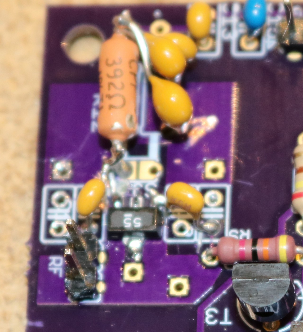
As you can see, I moved the RF output components much closer together. I added an additional ground plane to the top. I added more bypassing and coupling capacitors. It still didn’t work worth a damn. Here’s a picture showing how I ended up soldering the caps directly to the GALI-55:
You can also see lots of bypass caps soldered directly to the bias resistor. That was one of my many attempts to quiet down the interference.
Problem #3 – the impedance is messed up
The author had a nice write-up on a stepped attenuator that you can build. I decided that wouldn’t fit nicely in my case, so I’d just use a pot. The author used a pot (in addition to his attenuator), so surely I could just grab any old pot and use that. My attenuator consisted of a 500 ohm pot.
What happens when you do this is you screw up the impedance of the transmission line to the scope. This causes RF energy to be reflected and leads to additional reflected waves on the output. I wasn’t completely an idiot about this, I knew it happened, but the allure of using a $0.79 pot out of the junk box instead of building some complicated attenuator made it worth a gamble. I cut the pot out of the circuit and instead wired the RF output directly to the BNC jack.
I have a 0-10dB stepped attenuator on order from ebay. That’s going to be my “fine” RF control. My plan is to install that, along with a 20 dB toggle attentuator. That’ll get me 0-10 or 20-30 dB of attentuation. The stepped attenuator on order from ebay was $30. Let’s hope it’s a good one, and hope it fits.
Problem #4 – frequency variations at 80Mhz – 100 Mhz.
The RF generator was great, until I ramped up to about 80Mhz, then all sorts of weird crap started happening. First it was a single divergent frequency wave. Then there were all sorts of additional parasitic waves. The output was useless at this range. Again, the N&V author gave me some tips. He pointed to a ground issue, in particular in the vicinity of the RF selector switch.
The selector switch I used has a lot of metal components. The ‘nose’ of the switch is metal, as is a plate on the back of the switch. The switch was mounted to an aluminum front panel, and that front panel was conducting noise right into the switch assembly. The solution ended up being two-fold:
- Ground the switch itself. I soldered a ground wire to the metal backplate of the switch. Robert suggested using a 0.001uF capacitor. I tried various capacitors, but ended up just wiring the switch body straight through to ground.
- Ground the enclosure really well. When I first started this project, I made the mistake of trying to isolate the enclosure from the circuity by using insulated RF jacks, insulated standoffs, etc. My enclosure was completely isolated from circuit ground. It seemed like a great idea at the time, but I think in reality the enclosure made a great antenna and conducted noise right into the RF selector switch. To quiet it down, I replaced the insulated RF jack with a non-insulated one, and added ground pigtails from the power supply, opamp, and RF boards to the case.
Problem #5 – putting the lid on makes the RF generator go nuts
I thought I had it all working. Then I went to install the lid, and all of the waveforms below 10Mhz got all sorts of nasty distortions. Simply flexing the lid or moving it back and forth would have a significant effect on the waveforms. Crap. Simply moving my hand around inside the case would cause distortions. I had figured that I would be grounding the lid, and therefore it would not present a problem. No so.
The problem here turned out to be RF interference, again from my lack of experience with RF circuitry. I was smart enough to use coax for my RF cables, but I had made the decision to use 0.100 pin/socket headers since I’m familiar with those from my digital projects. They make plugging and unplugging boards really easy. Well *duh*, there’s a reason why people use shielded coax connectors. That little 0.100 pin header and 0.100 socket makes an excellent RF broadcast antenna. RF energy comes shooting out of it, bounces off the walls of the case, gets reflected back into the oscillators, etc. It’s a mess.
So what I ended up doing was shielding my 0.100 header by wrapping some copper foil tape around it and attaching that foil to the braid of the coax. This got me about 80% there on quieting down the interference.
The remaining 20% of fixing came from adding an RF shield right above the circuit board. I ended up using some tin metal and some more copper tape. Now I can put the lid on the RF generator without it going completely apeshit crazy.
This write up is very informative for me. I started to build the RF Sweep Generator version from the Dec 2013 issue of NV but I shelved it after being unable to get any of the VCO bands to give an output above ~ 90Mhz. I tried all sorts of methods. First I did the standard buildup of conformal coils on the rotary switch but there was too much stray capacitance in the leads get a stable output. The inductor values given in the article (which I used initially) gave me output frequencies well out of the expected bands (tolerances?). I did a complete overhaul of the RF tank section, used an SMT 1404 mounted directly beneath the MC1648 on the solder side of my RF board. I used ground plane layouts, shortened all the critical RF connections, etc. No luck! I think I laid out and etched 3 different RF boards with no luck. I even ended up (on my final attempt) winding RF tank coils on appropriate toroidal cores from micrometals. I got great signals, beautiful sine waves on the scope but it hit the wall every time at 90 MHz. Even a straight wire short in the tank didn’t help. I wonder if my GALI was affecting the output somehow in the higher range. It’s worth a look at least (once I finish my current project). Thanks for the great article and I’ll definitely check your videos on YouTube.
Good luck with your generator. I have found the author of the article, Robert Reed, to be very helpful. I think his email is in the N&V article.
I think most of my grief in the circuit came from the GALI. It seems extremely sensitive, and I’m not a professional RF engineer and I make mistakes! 😉 I’m not sure if I describe this in my blog post, but I ended up putting shielding all around the GALI and grounding the shielding. I think part of my problem may have been that I was sloppy with the RF connections, and any unshielded short bit of wire (such as the 2.54mm header that I used to connect my output cable) functions as a small transmitter that sends RF back into the circuit and causes it to misbehave in unpredictable ways. If I ever have another board made, I’ll put an SMA jack right on the board. I spent hours fussing around with that GALI circuit trying to understand why it behaved like it did.
Also check out one of my future blog posts titled “Ebay VCO Module Evaluation”. There a Chinese Ebay seller that sells a module for ~ $20 that uses the MC1648 VCO chip. It has one inductor on board and yields a 70-200Mhz range. While it doesn’t offer the features of Robert’s design (no modulation, only one band, etc), it was nice having a reference design to compare to.
Thank you for this incredibly informative post. I learn the most when engineers share their failures and difficulties and when it comes to working with RF information like what you shared in your post is golden. I’ve been working on a sweep generator for HF that uses a few MMIC’s (MCL Mar-x series) for wideband amps and an AD8307 detector, output is into a scope in XY mode. There are many good articles that i’ve used as references including:
Stable Wideband Sweep Generator – W7BAR – HamRadioMag June1981
Solid-state RF Signal Generator – HamRadioMag – July 1970
Lab Type RF IF Sweep Generator Using ICs (edit) – 73 magazine – November 1972
Crystal Parameter Measurement and Ladder Crystal Filter Design – QEX Fall 2003
A Compact IF Sweep Generator – HamRadioMag – Jun 85
An IF Sweep Generator – W2ZUC – HamRadioMag – Jan 87
to name a few. There is a Nuts & Volts sweep generator article that is accessible online for free (w/o subscription) that is extremely similar in design to the 73 magazine article I listed above. It uses an MC1648 which can be purchased for around $10.
Your article is a very wonderful resource as well and I thank you kindly for taking time to write it up and share. I build all of my RF circuits using double sided copper clad that I get from ebay for dirt cheap. I use single sided for VFO circuits though. A simple scribe tool can be used to cut isolated islands into the copper clad. I’ve written up an article about how to do this (it’s very easy) at http://freestateQRP.blogspot.com/ Using a method like this (or Ugly style or Manhattan style) when building RF circuits helps avoid a lot of issues encountered when designing a traditional type PCB because the copper serves as a single large ground plane. These ground plane circuits are then enclosed by soldering sides and a lid directly to the PCB using more double sided copper clad material. There are plenty good examples of this technique online. Drill a hole for SMA or BNC bulkhead adapters right into the copper clad results in a nice RF tight enclosure. Feed through capacitors allow DC signals to enter and exit with little issue. Feed through caps can even be designed into the output networks of circuit stages and used to directly feed an RF signal to the next stage/enclosure.
Thank you again for your excellent post and I wish you the best of luck in all future designs. Keep your iron hot!
-dh
I built quick and dirty RF ganarator with AM and FM modulation, and sweep function based on a DDS chip. Being mostly digital it takes much of the problems out of equation, but it is basically limited to 62.5 MHz. For the FM band it is using the property of the digital generation to mix the output frequency with clock, this makes it usable in the broadcast FM band as well. Would be cool if someone would design PLL module that would allow it to go to higher output frequency.
See http://www.nomad.ee/micros/rfgenerator/