In this post, I restore a GRiD Compass computer, and I build a speech synthesizer for it.
Background
The GRiD Compass has been on my most-wanted list for a while because it is an early computer that makes use of Magnetic Bubble Memory. I’ve restored other bubble memory computers, such as the Teleram Portabubble. I’ve added bubbles to my RC2014 projects. I built a standalone basic bubble computer. I added bubbles to my Heathkit H8 and to my Multibus computers. I’ve done lots of bubble projects, but the GRiD Compass was the standout that was missing.
The GRiD Compass features 384K of bubble memory. It can run either GRiD’s own operating system, GRiDOS (aka CCOS), or it can run MS-DOS. MS-DOS is probably the easier of the two as it’s a capable operating system that many people are familiar with.
I bought the compass on eBay.
The toughest computer!
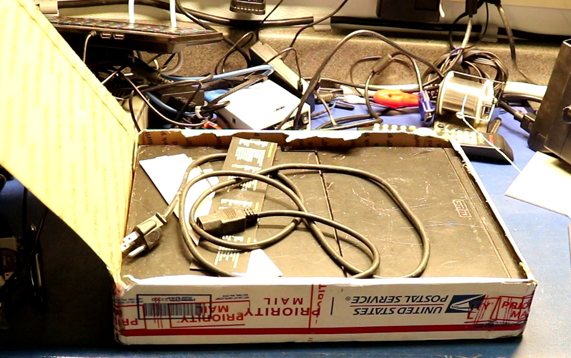
The seller shipped the computer to me in a USPS priority mail box with absolutely no packing material whatsoever. He actually extended the box ever so slightly because the computer was too big. It traveled across the nation via USPS this way. Did it harm the compass? Of course not! One of my viewers on youtube said that back in the day he dropped a compass off a roof onto a concrete slab, and the most it suffered was a scratch.
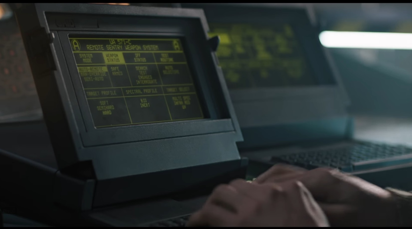
The computers have a magnesium case and they’re built to withstand abuse. They also have a decidedly military aesthetic to them, being the computer of choice used in the movie Aliens! We all remember that scene.
First Boot
Anxious to try it out, I plugged it in and flipped on the power switch and I was greeted with this:
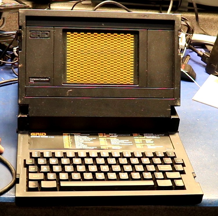
That checkerboard pattern looked like bad news. The good news was that the display was working, but my first guess was that there could be a logic board problem. Just to see if a different pattern would come up a second time, I flipped the power switch off and then back on, and I was greeted with … MS-DOS!
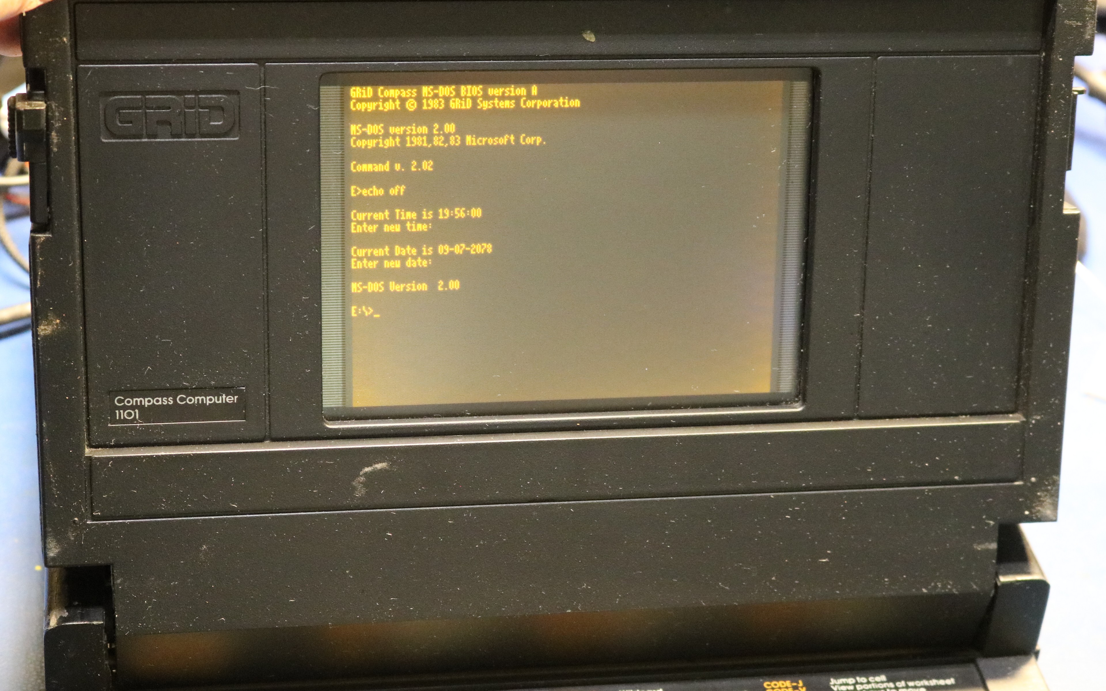
It booted up just fine, a plain vanilla MS-DOS 2.00 installed on the bubble memory. I powered it on/off and it continued to boot! However, I noticed a pattern. If I shut it off for several minutes and then turned it back on, there would be a boot failure, which would then be resolved by a quick power-on/power-off cycle. My best guess was that there was a power supply issue, perhaps a capacitor problem. I set about to take it apart.
The teardown
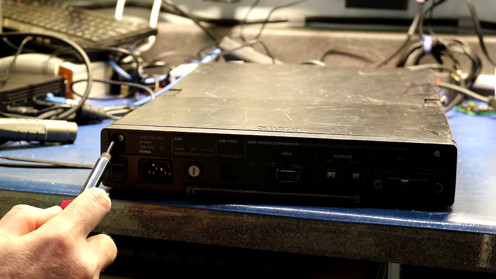
Start by removing the two screws under plastic caps on the back:
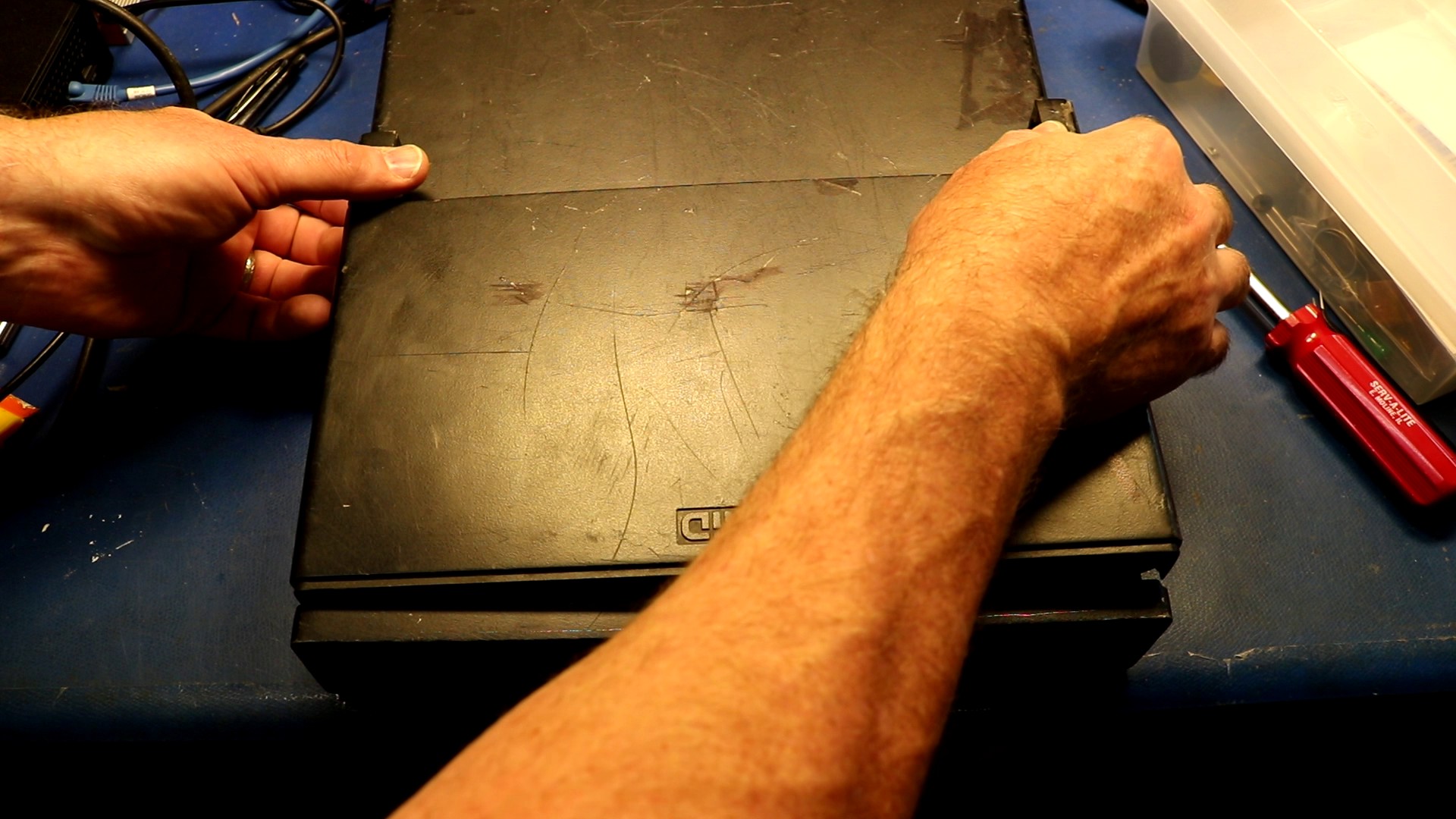
Next up, push the top cover gently forward and then lift it out:
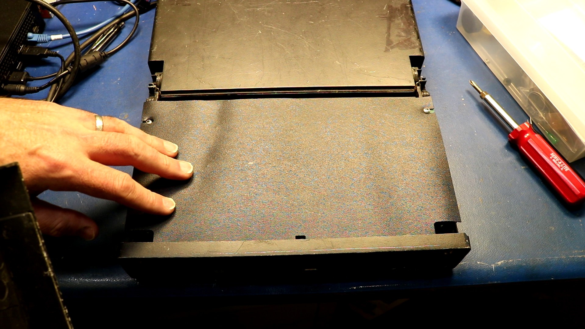
Underneath is a plastic cover:
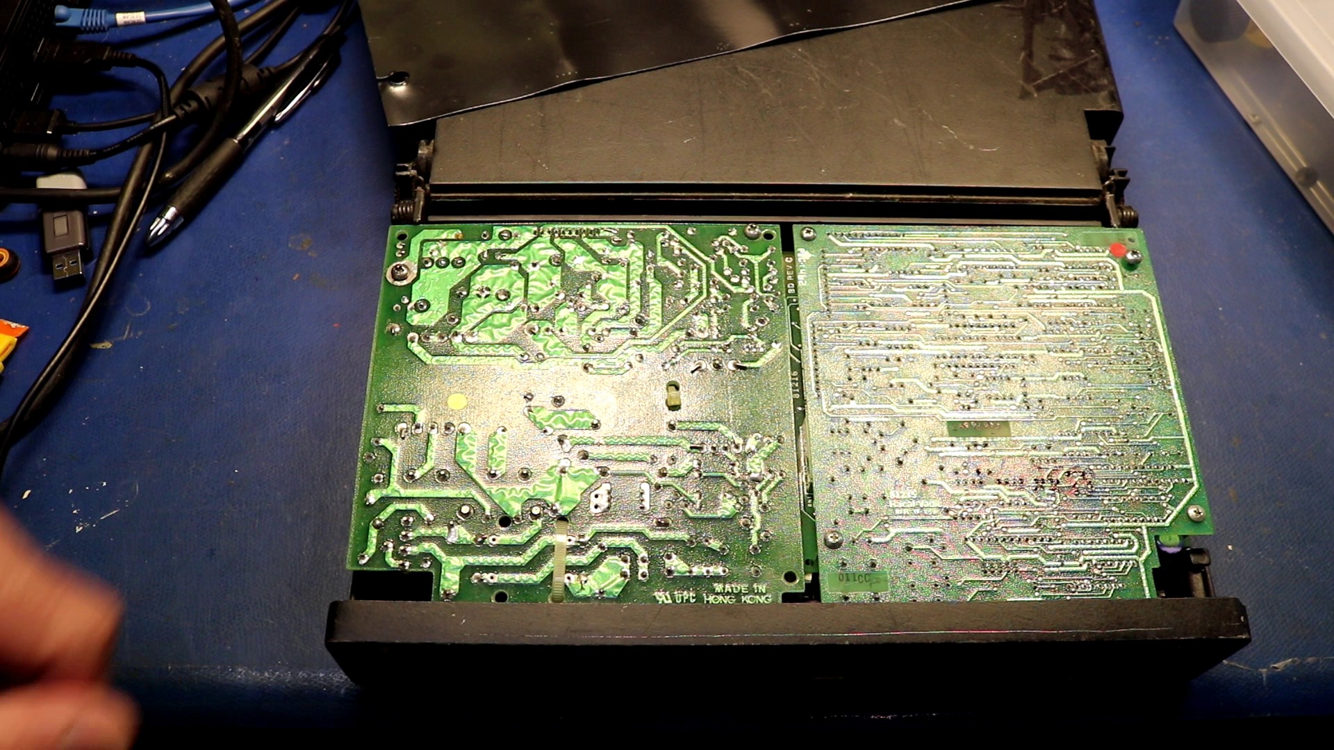
Start by removing two screws, then you can tilt out the power supply. After this, one screw is all that’s holding the modem in (two screws on the modem board hold the top modem board to the bottom). Remove that screw, pull some cables, and you can tilt out the modem board too.
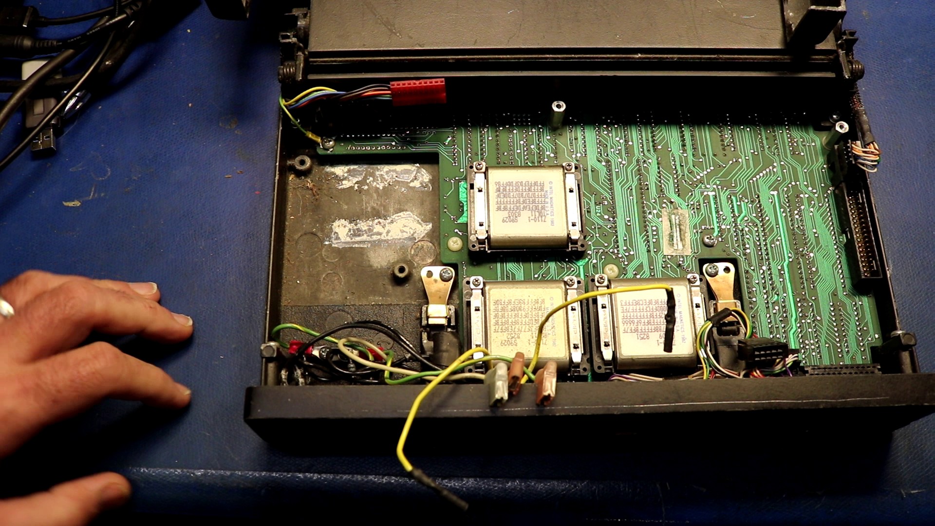
Under the power supply and modem is the main board. People recommend you remove the lithium battery because it may leak:
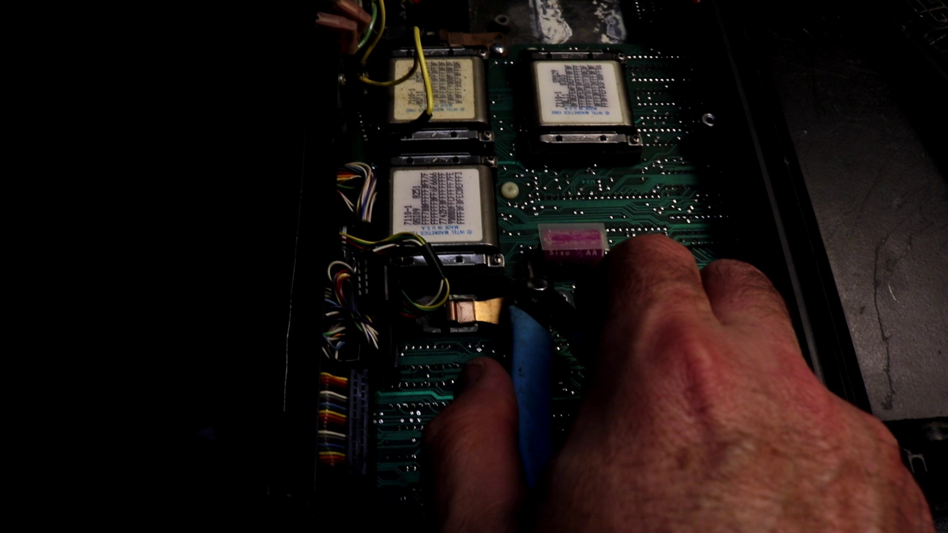
Here’s a good picture of the main board with the battery already removed. You can see the three Intel Bubble Memory devices:
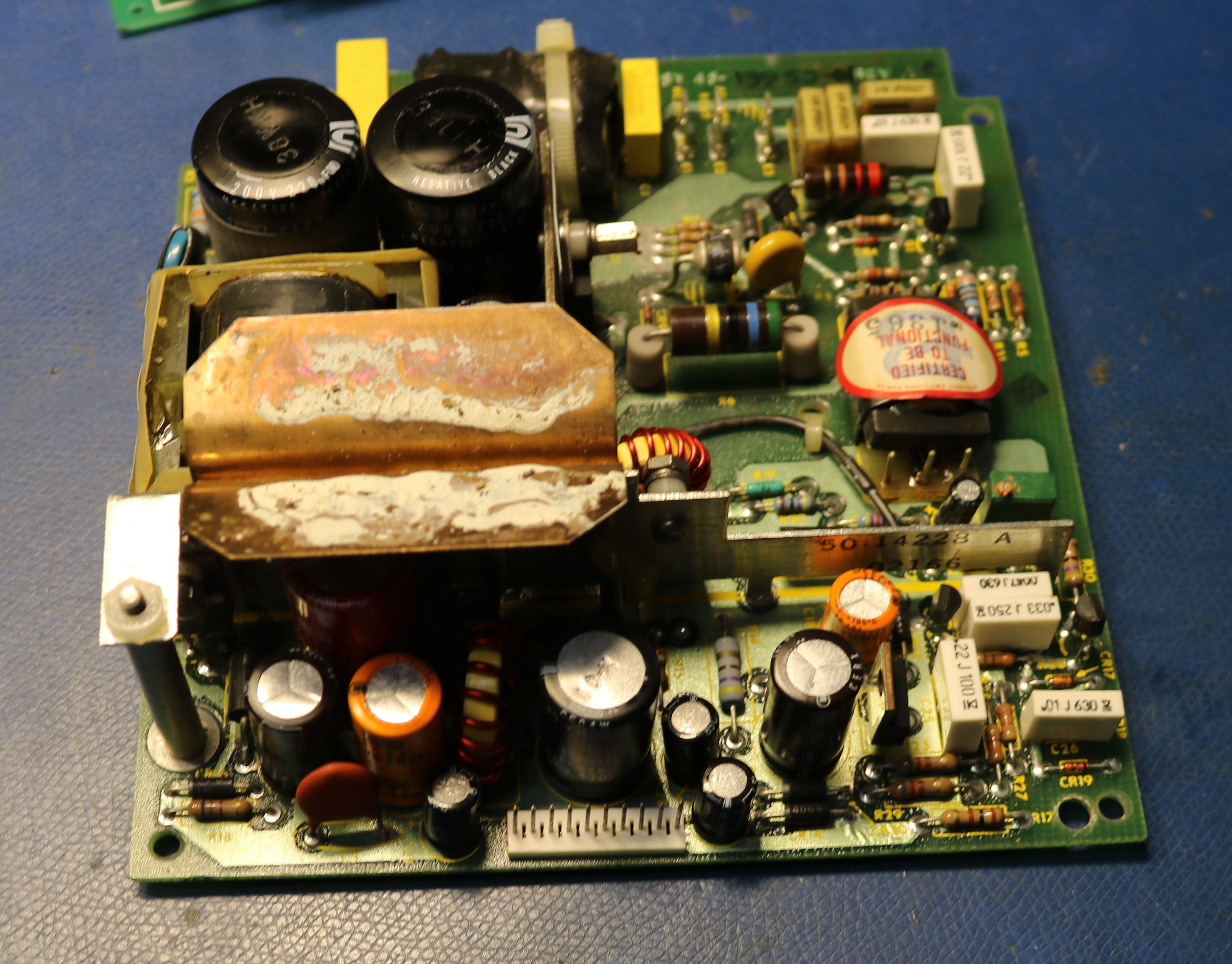
Here’s a picture of the power supply:
The actual problem — operator error!
After all that, I realized the problem with my unstable boots was quite simple. I had left the power switch set to 220V instead of 110V. Always check that first!
After setting the “Line Volts” switch to the proper position, the computer now boots correctly every time. Oh well, it’s not like I didn’t need to open it up to remove the lithium battery anyway.
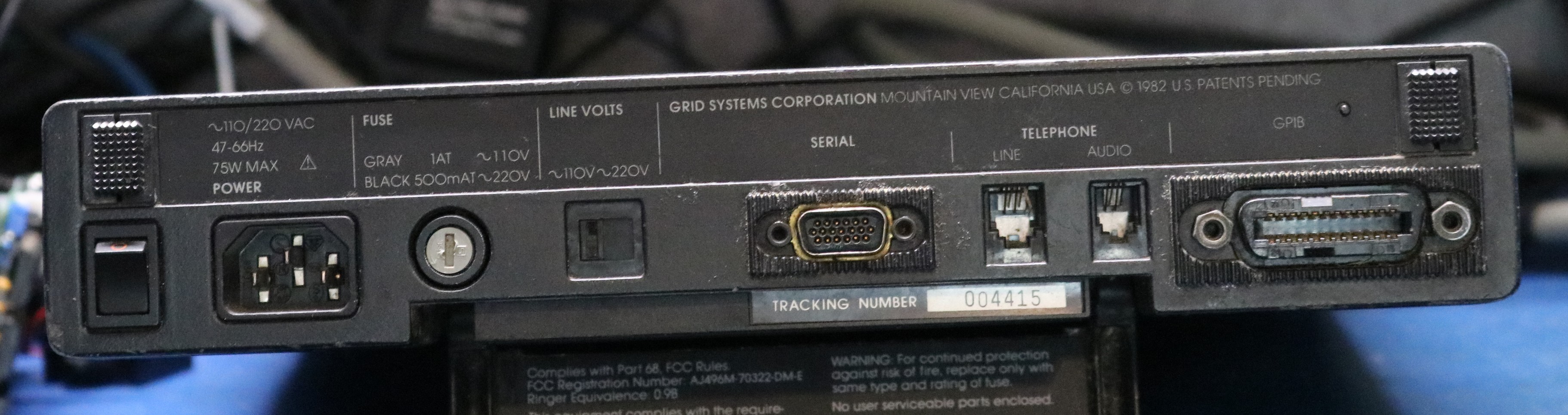
This is a good time to take a look at the back. From left to right we have:
- power switch
- AC power input
- fuse
- line voltage switch
- serial port — this is a funny high density 19 pin connector that is hard to source
- telephone line and handset jacks
- GPIB — this is how you can attach peripherals such as the printer
Now let’s build ourselves a speech synthesizer.
I’ve made this my trademark — with any new vintage computer I implement a speech synthesizer. Usually this results in me designing an add-on board or other module, but the GRiD is a little bit different. There’s not much room inside of the thing unless I was to get rid of something unnecessary (like the modem, which I am actually considering). The RS-232 port uses a funny 19-pin connector that is very rare and expensive, so RS-232 is out. That left me one practical option, the GPIB connector.
The GRiD Compass used GPIB for several peripherals including disk drives and printers. This provides me with an easy avenue for adding a speech peripheral. I’ll make it a GPIB device, and I’ll leverage the GRiD’s built in GPIB printer support. To make the GRiD talk, we’ll merely have to send text to LPT1:
The next choice was which speech synthesizer to use. I’m familiar with several — SP0256A-AL2, Votrax SC-01A, SSI-263, Digitalker, and TMS-5220. In fact, I have implemented them all as multimodules. This gave me an idea. I’d implement a GPIB multimodule carrier board that will allow me to plug in the multimodule-based speech synthesizer of my choice.
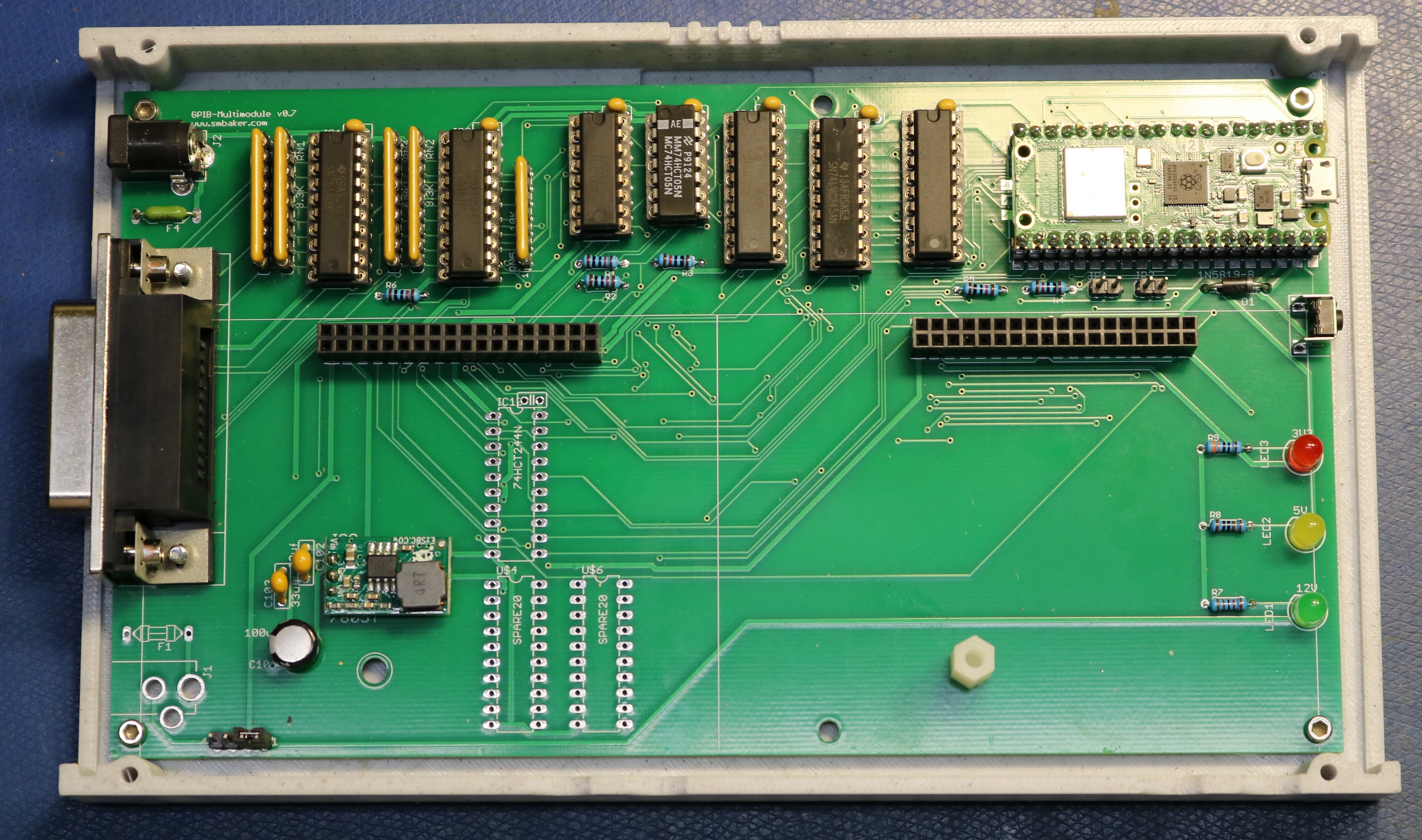
Above we have the GPIB multimodule board. I decided to use a raspberry pi pico 2 W as the controller for the board. The Pico is responsible for speaking the GPIB protocol and implementing the text-to-speech algorithm.
Moving from left-to-right across the board, we start with the GPIB connector. Then we have the 75160/75161 GPIB drivers and their associated pull-up/pull-down resistors. Next up is some logic, including level shifters and buffers/latches. There are two reasons for this logic: 1) the pico is a 3.3V device and the 75160/75161 are 5V devices, and 2) I need to be able to share the Pico between the GPIB protocol and the multimodule sockets. There’s not enough Pico pins to service both simultaneously, so a pair of 74LVC245 buffers allow me to direct data to the right bus.
This is all shown in the schematic at my github repo, https://github.com/sbelectronics/gpib-speech.
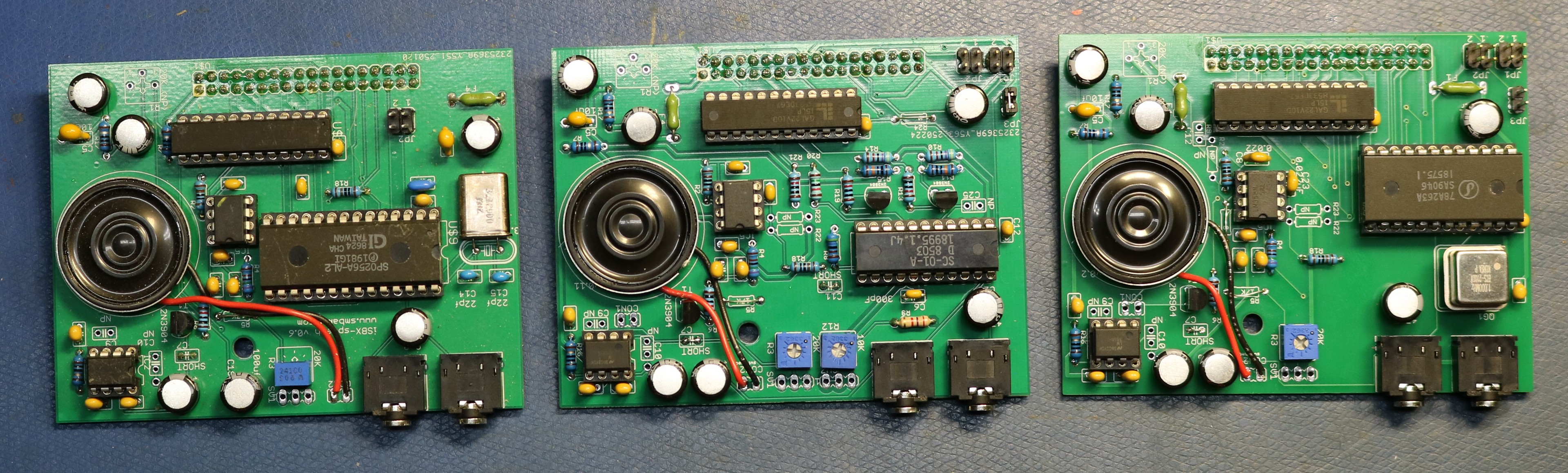
The speech modules
Below are the three speech modules I tested with this project:
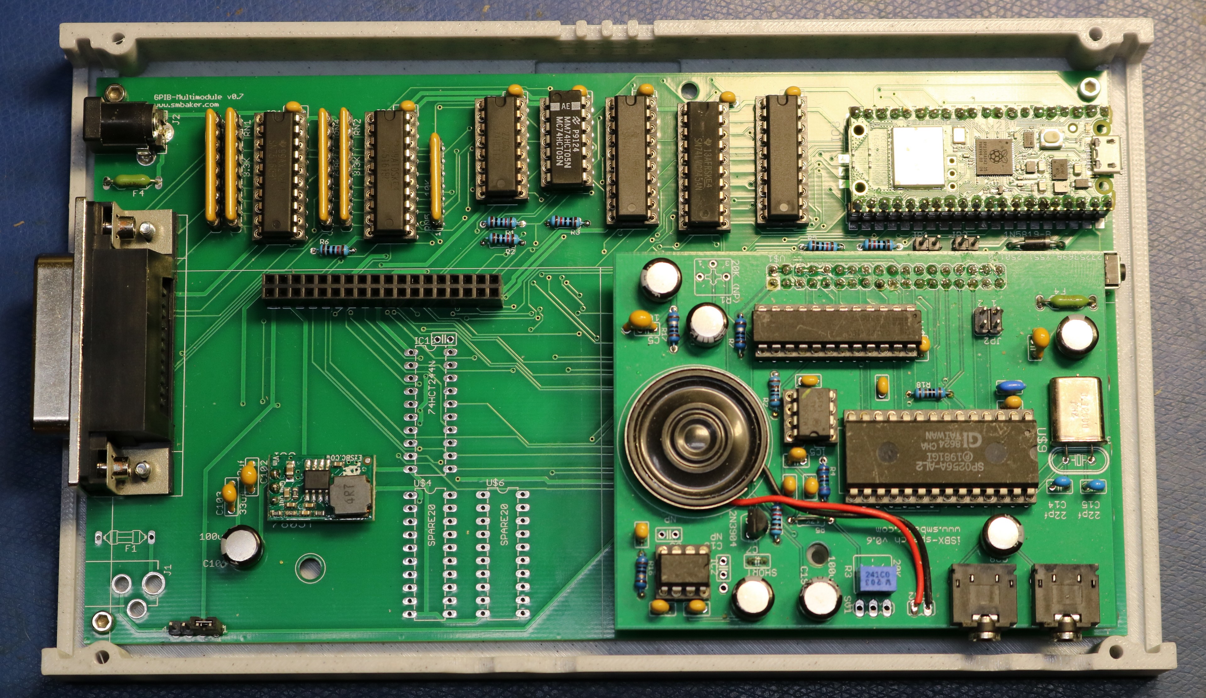
The module piggybacks on top of the GPIB carrier board:
The Speech Synthesis Software
The software is available at my github repo, https://github.com/sbelectronics/gpib-speech.
The gpib-speech firmware is a small Pico SDK / CMake project that runs on the carrier board’s Raspberry Pi Pico 2 W. The structure is layered: a bus layer that owns the shared GP0-GP7 data bus and arbitrates between GPIB-listen, GPIB-talk, and iSBX-active modes; an iSBX master that bit-bangs read and write cycles to the daughterboard’s chip-select decoder; a GPIB listener/talker state machine (ported from blackgpib with REN dropped and ATN polarity inverted to match our HCT05); a printer-style protocol handler that listens at address 21 and accumulates incoming bytes into lines on CR/LF; and a thin speech facade on top. Each layer is a couple hundred lines at most; the whole firmware is well under 2000 lines of code we wrote, plus the imported engine sources.
The speech-output side is the interesting structural choice. The three target chips — SP0256A-AL2, SC-01A, SSI-263 — have totally incompatible phoneme code sets and no obvious common abstraction, so I didn’t try to invent one. Instead the firmware has a tiny three-function contract (speech_chip_init, speech_chip_say, speech_chip_name) and four implementations of it (one per chip plus a TIL311-display “viewer” mode that pretends to be a speech chip but writes phoneme hex to the displays instead of audio). A single SPEECH_MODULE CMake variable picks which speech_<chip>.c gets compiled and linked — there’s no runtime dispatch, no vtable, no dead code for the chips you’re not using. Each chip module owns its entire pipeline from ASCII text down to register writes on the iSBX bus, including which text-to-phoneme engine it uses.
For the actual text-to-phoneme work I leaned on three existing engines, all from my previous projects: tts-c for the SP0256, typentalk (a C++ port of the original Votrax Type ‘N Talk firmware) for the SC-01, and tts-263 for the SSI-263. CMake’s FetchContent pulls each one in at a pinned commit, or you can point at a local checkout with a build-variable override and edits flow straight into the build — useful since I was actively hacking on all three engines at the same time. Each engine has its own API shape and integration quirks (tts-c uses a global outPhon symbol the chip module provides; typentalk uses a C++ Converter subclass; tts-263 takes a function-pointer callback) — these get hidden behind that same speech_chip_say contract so the rest of the firmware doesn’t care which engine is upstream.
In conclusion
I hope you enjoyed this blog post on the GRiD Compass and on the speech synthesizer that I created for it!
Hi Scott, great video on discovering that a GRiD compass from the mid 80’s still works.
I have have a long history with GRiD. I was hired in in the mid 80’s by SAI Technology who had licensed the GRiD architecture to develop a militarized version, beyond the 1107 Tempest model. I knew and worked with the developers of the 1101, 1107, its brethren and successors. John Ellenby, Carl Nakamura, Dave Paulsen and many others. I have an 1101. It still works, except for the poor old Tadiran primary Lithium cell.
You wouldn’t believe how many 1107’s were sold to the US govt.
I have never actually seen a 2107, although I remember hearing a story of one being returned to GRiD with a bullet hole in the middle.
The device that we produced at SAIT was a superset of the 1107. 512K Ram, 512K Bubble, known as the GRiDSeT-1177. In later years we produced a larger screen version, the 1179, and then a PC compatible version, 1179PC and then a 386 version. An SRAM version of the non-volital memory too, you see Bubble was fairly robust and to “De-Classify” it you often times used a 45 caliber to insure it was non-operational.
You should look for a hard disk for your 1101, IIRC it was the 2101, internally known as Chubby whereas the 2102 floppy was known as Chip. Also GPIB and a whopping 10MBytes…..
There was a line of “servers” as well… The GRiDServer, also ran GRiDOS and used the pseudo RS485 networking to talk to its clients, well before Ethernet.
There was also GRiDMail which we used extensively.
MS-DOS was almost an afterthought until the PC revolution made it necessary to be compatible.
In time “most govt. folks are coin operated” and would not buy our products when they could get a GRiD for a lot less $$. So our partner became our biggest competitor.
Just a little bit of history for you to ponder and do some additional research on…
All the best… I hope it’s been long enough that no one cares.
Fascinating stories, Ken. It makes me using a drill press to render my old HDDs practically-unrecoverable (at least without singificant effort) sound pretty mundane! I have been keeping my eye out for the 2101, but they seem few and far between.
Wow. Blast from the past with speech synthesizers: I grew up with ’em. That first board you used sure sounded like the Echo Plus board in I can’t tell you how many Apple IIe’s I used throughout school. It was miraculous stuff. When I moved on to PC’s, I’ve had several SSI263-based synthesizers: Sounding Board, Artic, AccentSA. … I still have *two* Accent SA’s, one still new in the box that was surplus. They don’t build ’em like that anymore.