In this post, I create a Real Time Clock (RTC) board for the RC2014
This is the second in my series of Z80 retrocomputer blog posts. If you haven’t already done so, then it might be helpful to start at the first post.
I wanted my first application of the Retrocomputer to be a Nixie Tube Clock. In order to do that, we have to make the retrocomputer tell time. There are a lot of real-time clock chips out there. Modern devices will usually be I2C or SPI. For something more compatible with the Retrocomputer, I went with the BQ4845. I got the idea of using the BQ4845 from a number of sites, most notably Nathan Dumont’s blog post.
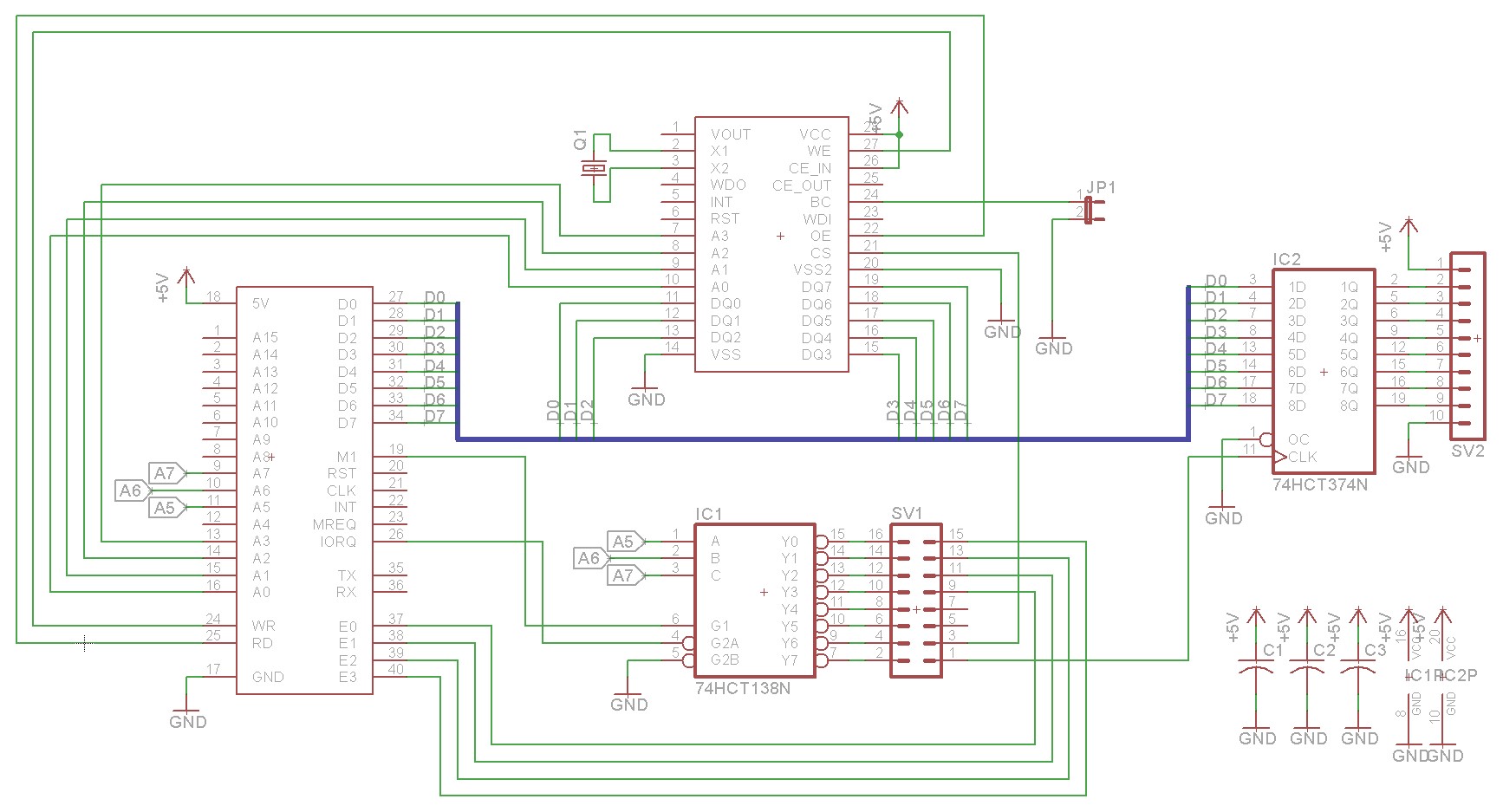
Here’s a schematic of the board that I developed:
Let’s start with the address decoding. This was already described in my first retrocomputing blog post, but it’s worth describing again here. The 74HCT138N is a 3-to-8 decoder. We will use it to take 3 of the Z80’s address pins (A5, A6, A7) and generate one of eight outputs based on those pins. This will map to IO addresses 00, 20, 40, 60, 80, A0, C0, or E0. By default I attached the RTC to C0 as this avoids both the RC2014 serial board (80-Bf) and the RC2014 digital IO board (everything below 80).
The 74HCT128N is also connected to the M1 and IORQ pins so that it will only be enabled when M1 is high and IOREQ is low. This ensures that we’re enabling on io reads and writes and not some other kind of operation.
The Z80’s RD and WR pins are connected to the BQ4845’s OE and WE pins. That makes sure the BQ4845 writes when the Z80 wants to write and reads when the Z80 wants to read. Address pins A0 to A3 are connected from the BQ4845 to the Z80, allowing the Z80 to select any of the 16 registers that the BQ4845 supports.
I also added an output driver to the board, a 74HCT374N. I knew that I wanted to be able to drive some of my nixie tube displays, and there was spare real estate on the clock board, so it seemed a logical place to add an output driver. The 74HCT374N is by default connected to Y7 on the 74HCT138N, placing it at IO port E0.
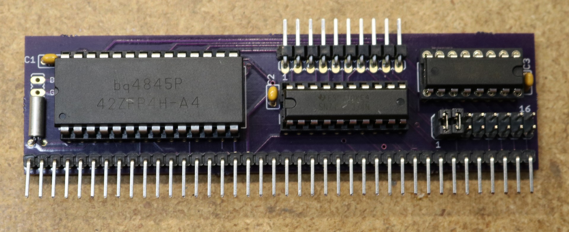
JP1 is a 2-pin jumper that allows you to attach a battery backup to the real-time clock should you wish to do so. Here’s an image of the assembled module:
Next up are the IN12 Nixie Tube display boards:
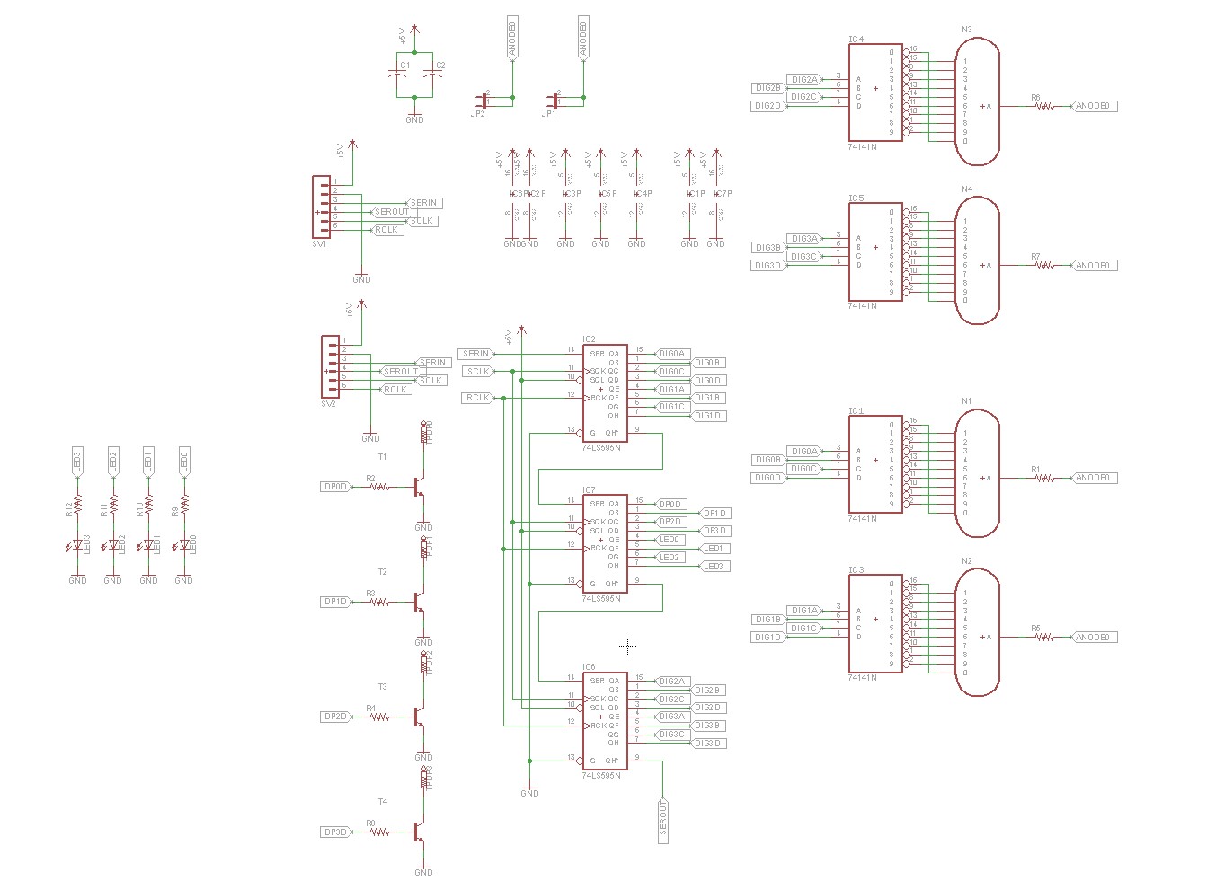
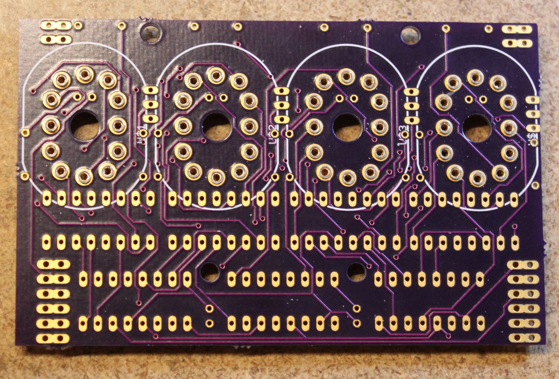
These are leftover boards from my Nixie Tube Calculator project. My final boards used I2c, but my first set of boards used 74LS595N shift registers, and shift registers are perfect way to interface to a retrocomputer like the RC2014. Each Nixie Tube Display board uses 3 shift registers for a total of 24 bits of output. I use two display boards, for a grand total of 48 output bits. Here’s a picture of the board, with mouser pins installed for the tubes, before I added the ICs:
To interface these boards to the retrocomputer, I wire the 74LS595’s SERIN, SCK, and RCK pins to the 1Q, 2Q, and 3Q outputs on the 74LS374N on the clock board. This allows us to bit bang out all 48 bits necessary to the display boards. We can do this fast enough, even from a program written in Z80 basic.
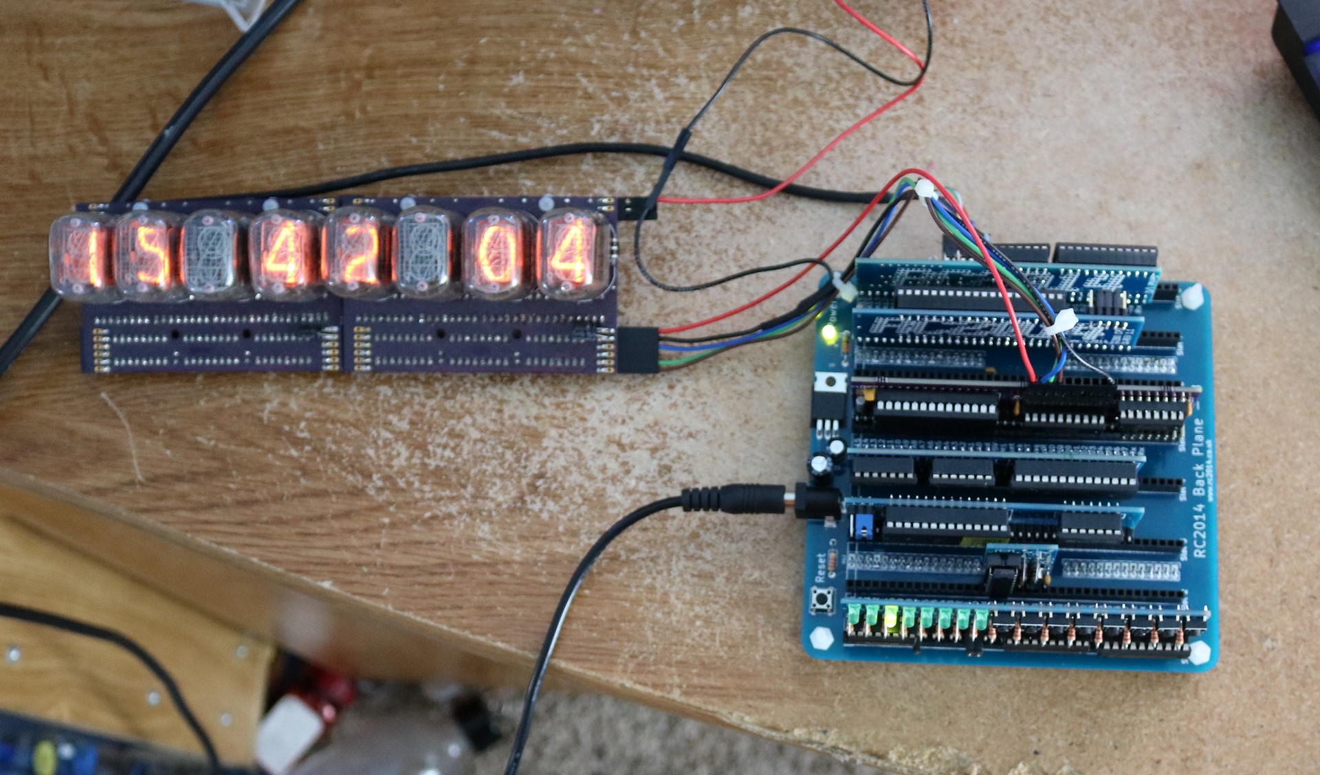
Here’s a picture of the whole thing wired together:
Source Code
The source code for the nixie clock is available in my github repo at https://github.com/sbelectronics/rc2014.
PC-Board Ordering
If you’d like the pc-board for this project, then you can use the button below to order it from Osh Park.

Comments (2)