This page describes how to upgrade the stock leading ignition on your Mazda Rotary Engine to a direct-fire MSD 6A ignition.
- Copyright (c) 2003-2004 Scott M. Baker.
Note: Please do not plagiarize this page! You are welcome to place a link to this page from your site, but please do not copy the contents (or pictures) from this site to your website without our express written permission (contact: sandrail@smbaker.com).
Acknowledgements:
- The direct fire MSD ignition was (to the best of my knowledge) first proposed by Paul Yaw at www.yawpower.com
Introduction:
First of all — why do you want to do this? Well, I have to admit, I did it mostly because I feel a need to tinker with things, and can’t leave any stock part alone. Seriously though, the MSD 6A box claims that you will get “less plug fouling”, “better performance”, “quicker throttle response”, and “easier starting”. Let’s hope all of that is true.
By performing this conversion, we’re getting two bonuses:
- Capacitive Discharge Ignition vs Inductive Ignition. The stock ignition is an “inductive” ignition. The inductive ignition was invented by Charles Kettering in 1908. An inductive ignition works by storing energy in the coil. This is done by applying battery voltage to the primary of the coil.Then, when you disrupt (i.e. disconnect) the battery voltage, the inductor will induce a current flow on the secondary of the coil, which gives you a spark. In the old days, the switching of the primary battery voltage on and off was done by points, these days it’s usually done by a magnetic pickup and a transistor. The disadvantage of an inductive system is that the the energy decreases as the RPM goes up, because there’s not enough time to fully charge the coil.
The MSD-6, on the other hand, is a capacitive discharge ignition. It works by storing up charge in a capacitor (inside the MSD-6 itself) of about 475 volts. The high voltage of this capacitor is then dumped into the primary of the coil, which induces an even higher voltage in the secondary (around 45000 volts), which will then give you your spark.
CD systems, as opposed to inductive systems, are able to supply a full charge, even at high RPM. An added bonus the CD system, is that at low RPM it can actually produce multiple sparks.
- Direct Fire vs Distributor. Your stock system fires through the distributor. If you look inside your distributor, you’ll find that it has a rotor inside. The rotor has contacts on it that match contacts in the cap. As the rotor is turns, it lines up the contacts for the appropriate spark plug, so that the spark from the coil will go to the right plug.
The problem with the distributor is that the contacts on the rotor do not actually touch the contacts on the cap — the spark has to jump a little gap inside of there. This is going to cause a loss of some energy. Other problems with the distributor include ionization of the air inside the cap (causing cross-fire) and dirty/worn contacts. A much better solution would be to eliminate the distributor, and fire each plug from it’s own dedicated coil.
This leads us to the direct fire solution. In a direct fire configuration, you have a dedicated coil for each spark plug. The coil is wired directly to the plug — there is no distributor “gap” sitting inbetween the coil and the plug.
The solution that we’ll end up with in this article is actually only direct fire on the leading spark plugs (recall that you’re mazda engine has two plugs per rotor: a leading plug and a trailing plug). The reason for this is that we can safely fire both leading plugs at the same time. One leading plug will be in the correct cycle and will cause combustion. The other leading plug will not be in the correct cycle and it’s spark will be “wasted”. This is, quite intuitively, called a “wasted spark system”. The wasted spark on one of the leading plugs does us no harm.
However, we can’t utilize a wasted spark system on the trailing plugs. The reason for this is that there is actually a chance of the wasted spark on a trailing plug igniting the combustion chamber in the incorrect cycle. This would be very bad, and would almost certainly lead to engine damage.
Thus, we end up with a hybrid system — a direct fire wasted spark implementation on the leading plugs (the plugs that do the most work), and the old distributor system on the trailing plugs.
Shopping List:
Here’s what you’re going to need to buy:
- an MSD-6 ignition. This can be a MSD-6A, MSD-6AL, Offroad MSD-6, etc — there’s several variants to choose from depending on the features you want.
- three (3) coils: one for each leading plug, and one for the trailing ignition. I suggest two nice new shiny MSD blaster-2 coils for the leading plugs. You can use stock coils if you prefer. Since we’re leaving the trailing ignition unchanged, a stock coil is perfectly acceptable there.
- a mazda distributor. The version with the magnetic pickups / ignitors is better than the version with the points. The version with the ignitors attached to the distributor is better than the version with the ignitors in a separate box.
- one good mazda ignitor for your trailing ignition (use the one you already have with your distributor)
- a set of do-it-yourself spiral wound spark plug wires— the kind that come with one end of each wire preassembled, and the other end unassembled (so you can cut them to length, and make up custom cables). I used accel 8mm spiral wound wire. The MSD manual specifically states to use spiral wound rather than solid core wire.
- optional: if you have a broken ignitor (or an ignitor that you’re willing to sacrifice), you can use it’s carcass to make a nice adapter plug to connect the MSD-6 to the magnetic pickup in the distributor.
Wiring overview.
-
- Connect the MSD trigger wires (MSD green and purple wires) to the leading magnetic pickup in the distributor.
- Connect the MSD coil wires (MSD orange and black wires) to the coils
- Connect the MSD big red and big black wires to your battery
- Connect the MSD little red wire to switched ignition power
Here is a quick overview of what needs to be wired, so you get an idea of what needs to be done before we go into detail.
Making an adapter plug out of an old ignitor
- The MSD ignition is going to need to plug into the magnetic pickup in your distributor. If you remove an ignitor from your distributor, you’ll see that there’s a little two-pin plug on the distributor that mates with a two-pin plug on the ignitor.
[Note: You don’t have to do it this way — there are other ways to connect the MSD to the pickup, such as fashioning your own plug, or cutting the pickup wires inside the distributor and attaching your own connector — but I think this is the cleanest way to do it]
Here is a picture of an ignitor, so you can see what I’m talking about:
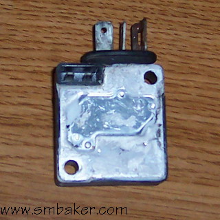 |
Picture of a J-109 Ignitor
You can see two different plugs here. On the top of the ignitor is a pair of blade terminals that are fairly easy to hook up to. On the side of the ignitor is the two-pin plug that mates to the magnetic pickup in the distributor. |
As you can imagine, that little two-pin plug in the side of the distributor is not the easiest thing in the world to find a connector for. However, if you’re lucky enough to find an old ignitor, then you have the perfect connector!
First thing to do is to cut open your ignitor and remove the guts. I cut mine open with a sherline milling machine (a very useful tool!). You could also probably cut one open with a small cutting wheel on a dremel. Be careful to not cut too deeply — all we need to cut through is a relatively thin metal cover on the ignitor.
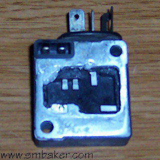 |
Picture of a J-109 Ignitor with the guts removed.
Here, I’ve cut open the ignitor and removed the components that are inside. The components consist of a small circuit board and some parts, and lots of “gunk” that feels kind of like wet silicone. |
In the above picture, you can see that there are four “pins” inside the ignitor, that connect to the connectors on the outside of the ignitor. The two pins on the right connect to the plug at the top, and the two pins on the left connect to the plug on the side. So, what we need to do is to wire the two plugs together.
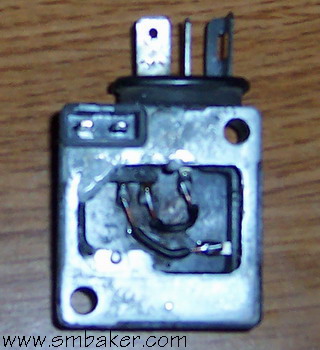 |
Picture of J-109 ignitor with wires installed.
Here you can see I’ve writed the pins for the top plug to the pins for the side plug. Make sure to do a good job of soldering (no cold solder joints) and make sure your wires don’t touch. |
Voila! There you have it, we’ve turned an old ignitor into the perfect adapter to use to connect to the distributor. One thing to note — the way we’ve wired it, the wires kind of criss-cross. Take multimeter or continuity tester to it and you’ll see what I mean. The Right connector on the top plug connects to the left connector on the side plug, and the left connector on the top plug connects to the right connector on the side plug.
As a side note, I painted my adapter “bright blue” (see pictures below) to ensure that it never gets confused with a “real” ignitor.
Wiring Step #1: Connecting the MSD to the magnetic pickup in the distributor
-
- Build an adapted from an old ignitor (as I described above). This is (in my opinion), the best way to go.
- … or … Try to mutiliate the MSD plug into one that will fit the plug on the distributor.
- … or … Cut off the plug in the distributor and install your own plug (butt connectors or spade terminals, or whatever) in it’s place.
- MSD Green Wire —> Magnetic Pickup Red Wire
- MSD Purple Wire —> Magnetic Pickup Green Wire.
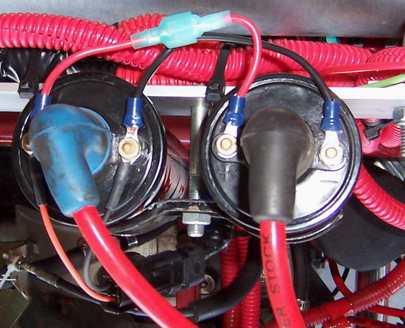
The magnetic pickup tells the MSD when to spark. Your distributor has two pickups inside of it, one for the leading ignition and one for the trailing ignition. The leading ignition pickup and ignitor are towards the front of the motor (the side of the motor with the pulleys and water pump).
Here is a picture of the distributor. The leading ignitor is shown in bright blue. You can see the little red and green wires going from the magnetic pickup to the ignitor.
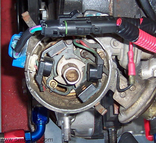
Remove the leading ignitor from the distributor. It is held on with two screws. This will leave you with a little plug on the side of the distributor. There are a couple of choices about how to connect to this plug:
Okay, let’s assume you decided which of those three alternatives you want to do. Now, it’s time to connect the MSD ignition to the leading ignitor. We need to wire it as follows:
This is very important — get the connections right! If you wire it backwards, the ignitor will fire at the wrong time.
If you’re using the “old ignitor adaptor” that I showed you how to build above, then you can connect the MSD Green wire to the “C” terminal, and the MSD Purple wire to the “B” terminal. (Only do this if you’ve made the adapter that I showed you how to build — do not attempt to connect the MSD to a regular ignitor).
Wiring Step #2: Connect the MSD to your coils
-
- MSD Orange —> First coil +
- MSD Black —> First coil –
- Jumper wire from First coil + to second coil +
- Jumper wire from First coil – to second coil –
Recall that we’re going to connect two coils, in parallel to fire the leading spark plugs.
The MSD supplies an orange and a black wire to connect the coils. The orange wire goes to “+” and the black wire goes to “-“. We’re going to wire the coils in parallel, so this is how we do it:
Wiring step #3: The big red and the big black wires
- The MSD has a big red and big black that need to be connected to (unsiwtched) power and ground, respectively. There’s not much to say about this — just ensure that you do pick good places to hook them to. If you connect the gound to the chasis, make sure it’s a good spot on the chasis.
Wiring step #4: The little red wire and the little white wire.
- One last wire to go — the little red wire. The little red wire needs to be connected to switched ignition — i.e. power that turns on only when you turn on the key.
And then we have that one leftover little white wire. You can safely cut it off and cap it — it’s for points, which we don’t have. Alternatively, you can install a small hidden switch to between the white wire and ground, and use it has a hidden kill-switch / theft-deterrent switch.
Connecting your plug wires:
- You will need to fashion two new plug wires. The plug wires will connect from the two new coils to the leading plugs on the engine (the leading plugs are the lower plugs on the motor).
The Trailing Ignition:
- The trailing ignition stays exacly the same as it was before. You need to make no modifications there. Just to make sure we’re all on the same page here, you still have one trailing ignitor on the distributor, and it’s connected to one trailing coil. The trailing coil wire is connector the the distributor, and two trailing spark plugs are connected to the distributor.
Tachometer
-
- The “-” terminal of the trailing coil
- … or … The tach output on the MSD-6
There’s a couple of choices about where you connect your tach. You can connect it to either of these:
I prefer connecting it to the “-” terminal of trailing coil. The reason for this is simple. If the trailing ignitor fails, then your tach will fail, thus alerting you to the problem. As the trailing ignition really doesn’t do that much work, it isn’t that noticible should it fail. Hence this is a good way to tell. (If, on the other hand, the leading ignition fails, then you will most certainly be aware of it…)
Alternatively, you can connect it to the tach output on the MSD ignition. On my OffRoad MSD, this is a solitary green wire. On the other MSD versions, I think there is a plug in the side of the ignition — check your manual.
The one place that you should probably NOT connect it is to the “-” terminal of the leading coils.
The complete picture:
- Here’s a final view of the whole ignition system, as installed on my sandrail:
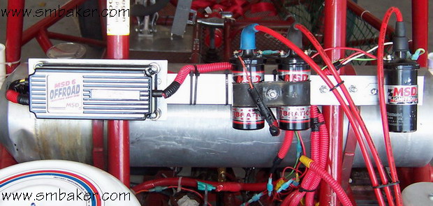
Above, you can see the MSD-6 OffRoad igntion unit, as well as two blaster-2 off road coils, and one stock coil.
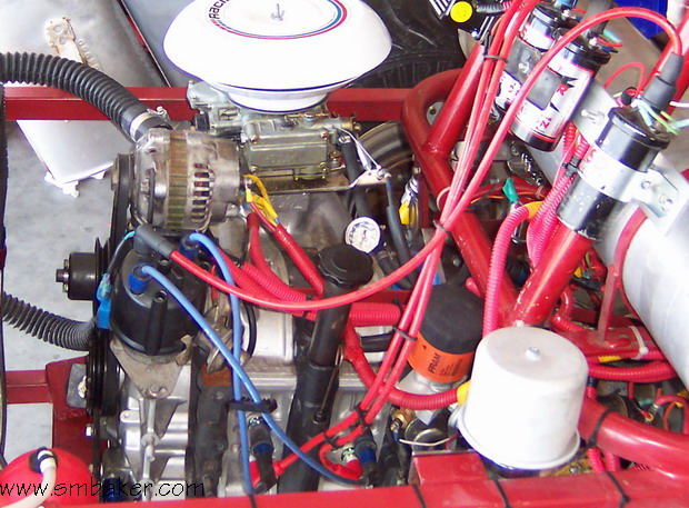
Below is a side view, showing the routing of the spark plug wires.
My 88 RX7 racecar with a 13B rotary was just converted from a two MSD configuration to a single MSD per your article. A long time ago I was a design engineer at HP. Is there a skematic of this design to help me understand exactly how this works. Thanks for sharing
I am in a proses of updating my ignition system from a RX7 1980 and taking out the factory relays. Do you have a suggestion? I also updated the distributor from points to electronic ignition. Will you share the skematic and more pictures.
Thank you,
Marcelo
How would someone go about doing this with the points type dizzy? i have a 1979 12A and am trying to make this conversion
I am also building a 1982 Mazda Rx-7 12a into a holley EFI system with the 6S MSD ignition system. Is there a diagram we could use to hook this up?
Hello, would a MSD 6 box be a good option for the trailing side, instead of the standard ignitor?