
Introduction
The Burke & Burke CoCo XT was a hard drive solution for the TRS-80 Color Computer. In an age where most people were content to have one or two floppy drives instead of a miserable cassette tape, a hard disk drive would have been almost unthinkable. The CoCo XT let you use standard MFM hard drives, such as the 20 megabyte Seagate ST-225, with an off-the-shelf PC/XT controller card. You could segment the drive into a series of MSAs, or Mass Storage Areas, each one with as much storage as a floppy or considerably more, and map them onto the coco’s drive numbers.
I’m not an OS-9 user, so I specifically wanted to use this with the color computer’s built-in Disk BASIC. Burke & Burke sold a separate product for that called Hyper-I/O, and most of what follows is about getting the two of them to cooperate.
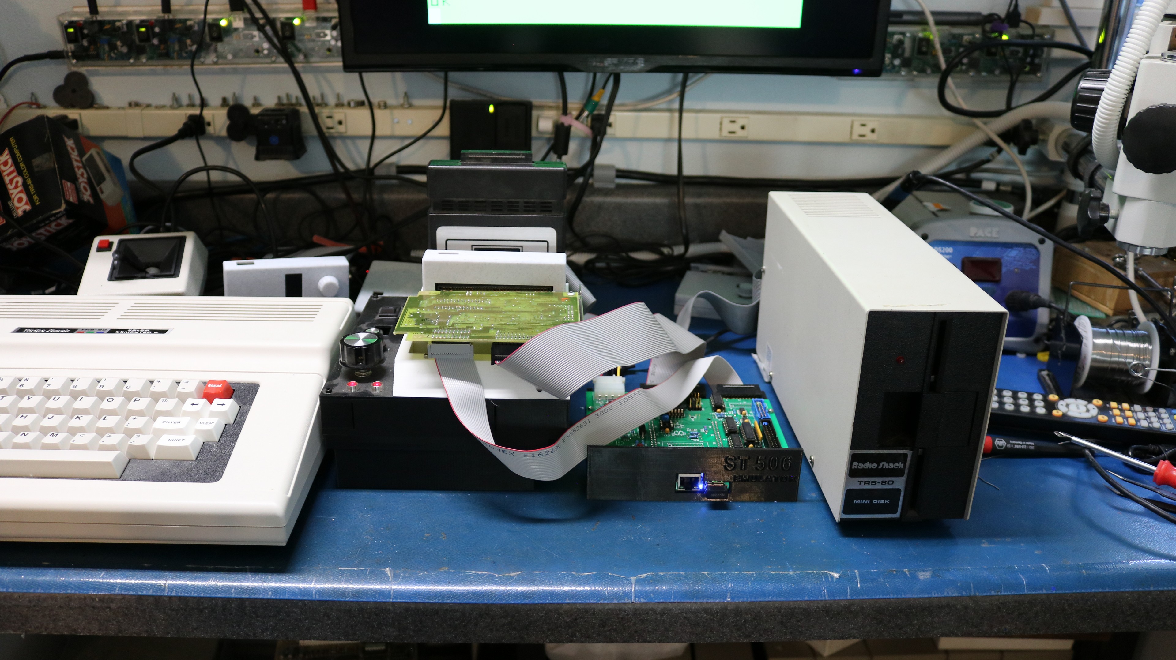
In this blog post I talk about my clone of the CoCo XT, what it took to get a drive initialized from BASIC, and how I ended up booting the whole thing from ROM. The schematics and Gerbers for the clone, along with a detailed set of notes, are in my GitHub repo at https://github.com/sbelectronics/coco/tree/master/cocoxt.
How the CoCo XT worked
The CoCo XT is a surprisingly small board. It doesn’t contain a disk controller at all. What it does is adapt the coco’s 40-pin cartridge bus to an 8-bit ISA slot, so that you can plug in the same Western Digital WD1002-WX1 style controller that an IBM PC/XT used. All of the hard work, encoding MFM data, stepping the heads, checking CRCs, is done by the controller card. The CoCo XT just has to make the coco’s bus look enough like an XT’s bus that the controller doesn’t know the difference.
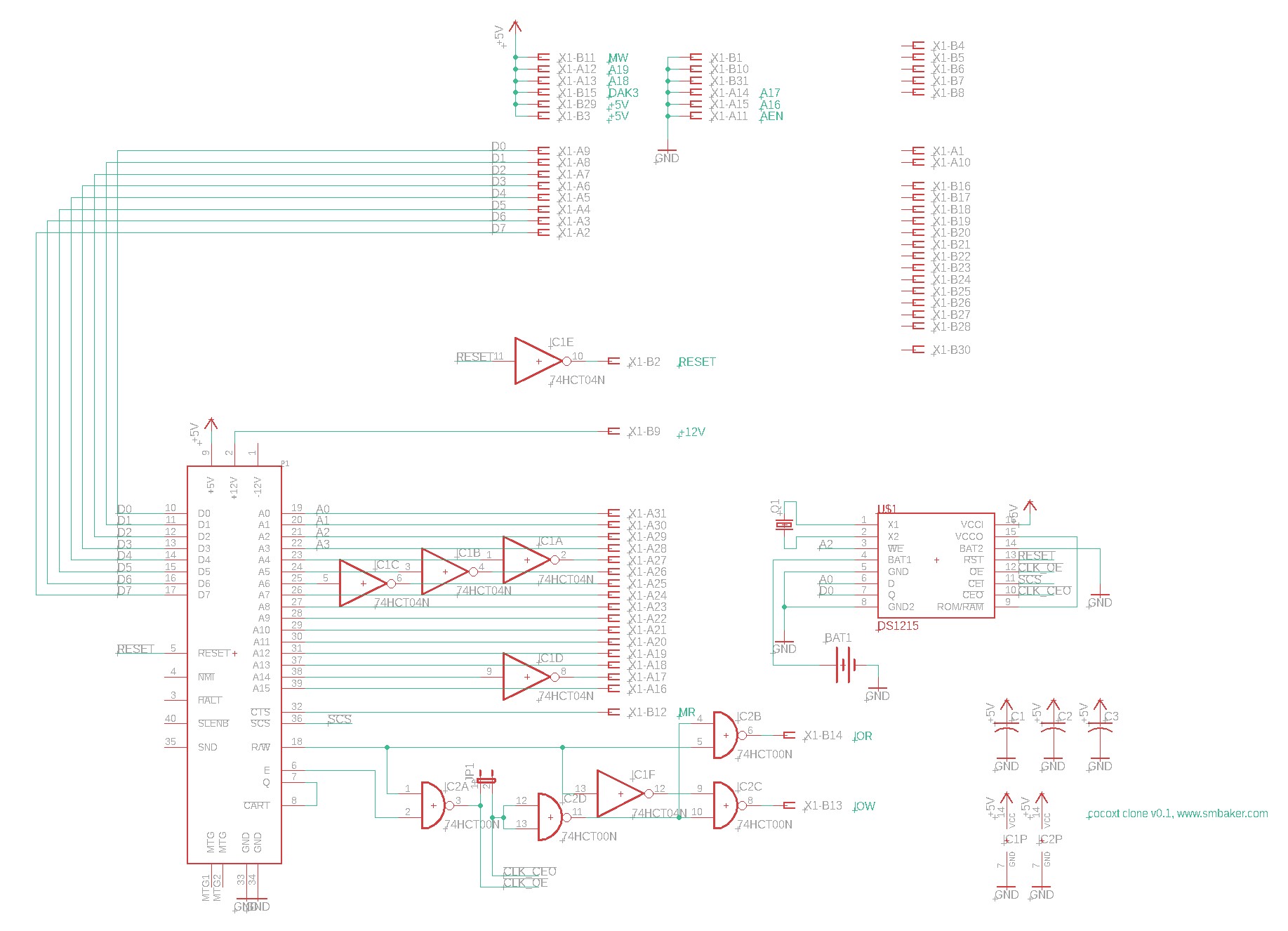
That takes a hex inverter, a quad NAND gate, and a little bit of cleverness. The XT controller wants to live at I/O port 0x320. The coco has no I/O ports; it has a memory window at $FF40-$FF5F that is decoded by the SCS line on the cartridge port, and the floppy controller already owns the bottom half of it. So Burke & Burke put the hard disk at $FF50-$FF53, and then inverted address lines A4, A5, and A6 on their way to the ISA connector. The low ten bits of $FF50 are 0x350, and 0x350 XOR 0x070 is 0x320. Three inverters and the controller sees the port address it expects. As a bonus, floppy accesses at $FF40-$FF4F come out as 0x330, which is not a WD port, so the two controllers never step on each other.
The same trick is played on A14. The upper ISA address lines are tied high and low such that when the coco reads $C000, the controller sees 0xC8000, which is the standard address of a hard disk BIOS ROM on a PC. This let Burke & Burke put an 8K boot ROM in the controller’s BIOS socket for OS-9 users. Since the address lines are scrambled, the ROM image has to be scrambled to match, which is why the XT-ROM dumps you find online come in “scrambled” and “unscrambled” flavors.
The other chip on the board is a Dallas DS1215 phantom clock. It sits in series with the SCS line and is invisible until you feed it a 64-bit magic pattern, after which it hands you the time. That is where the “RTC” in “CoCo XT-RTC” comes from.
On the software side, the controller formats the drive as 17 sectors of 512 bytes per track, the way any XT would. Hyper-I/O packs two of the coco’s 256-byte sectors into each physical sector and ignores the seventeenth, so BASIC sees 32 sectors per track. The disk itself is formatted with an OS-9 RBF filesystem, and each MSA is just a big file inside it. To BASIC, an MSA looks exactly like a floppy. You attach one to a drive number with `OPEN DRIVE 2,”/H0/A”` and from then on `DIR 2`, `LOAD`, `SAVE`, and everything else works as if there was a floppy there. The default MSA is a byte-for-byte clone of a 35 track floppy, 68 granules, but you can make them as large as 2.9 megabytes if you want to.
Building the clone
I designed the clone board back in 2022 based on a CoCo XT schematic that I found online [link to source]. I must have been distracted, because there it sat for the next four years until I had the coco out one weekend and decided to build it. My board is shown below.
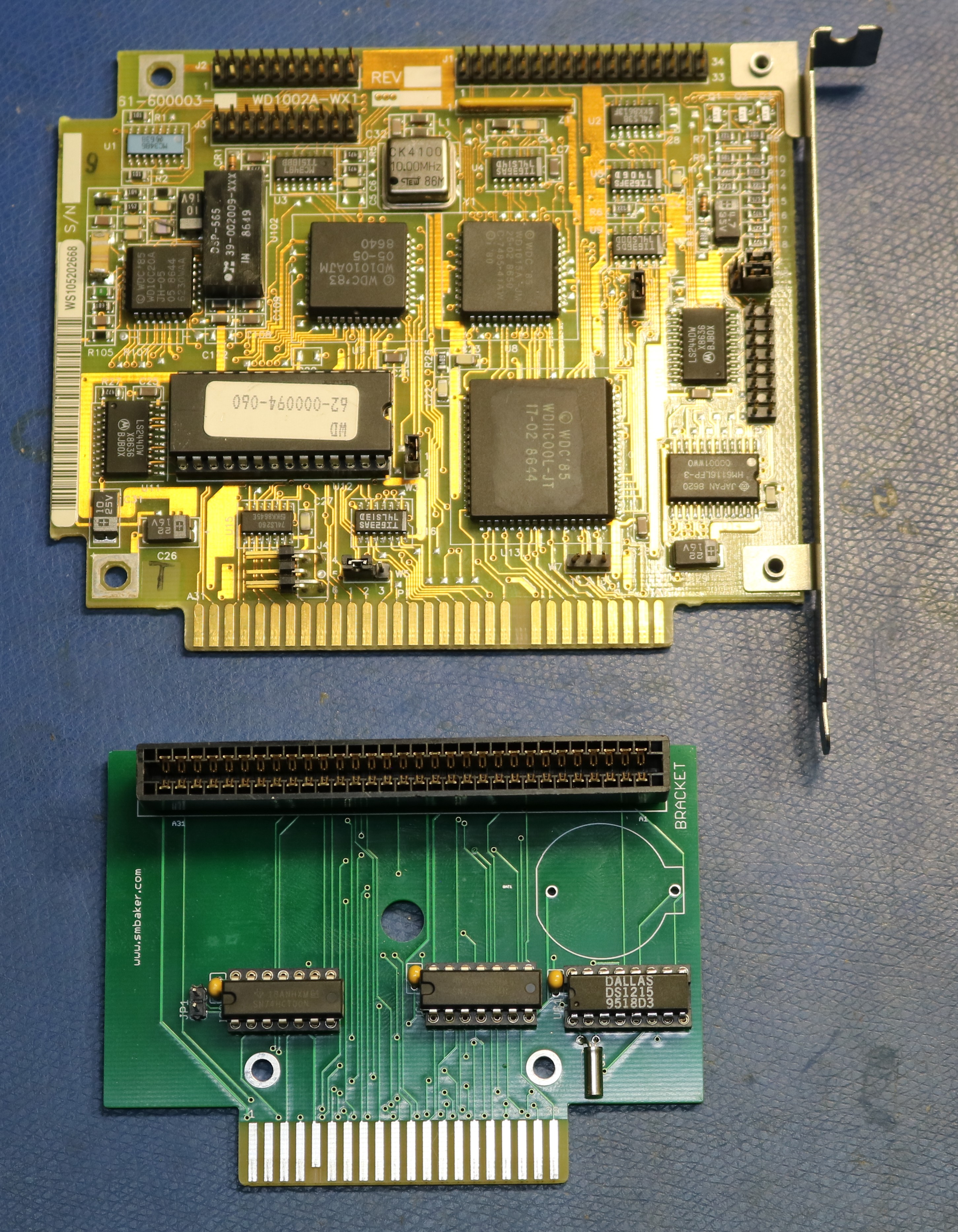
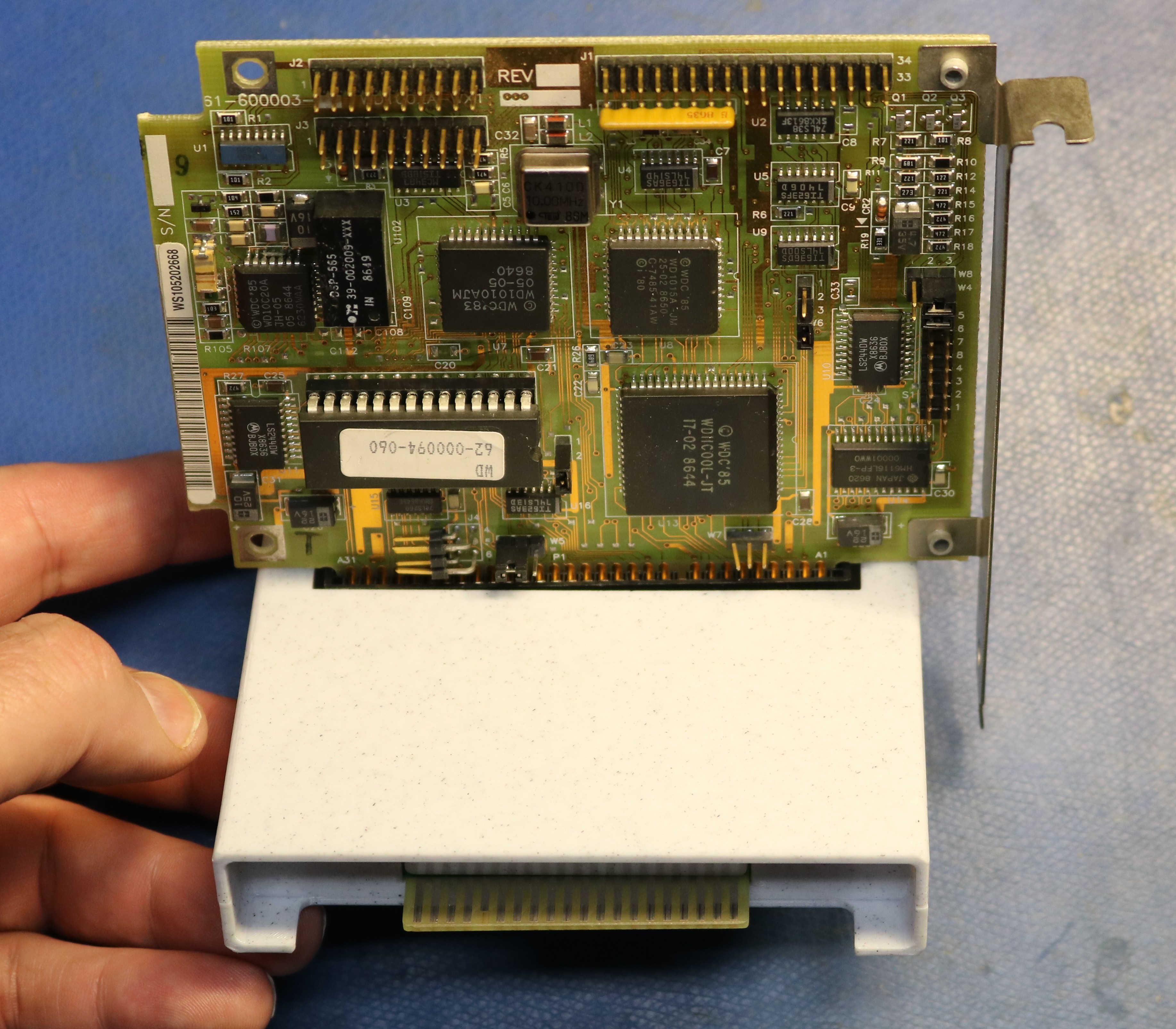
For my controller I used a WD1002A-WX1, and it plugs into the ISA connector on the board. Ideally this would use a right angle connector so that the controller sits parallel to the board, but when I built my prototype I only had vertical connectors, so I ended up with this somewhat inconvenient arrangement. The right angle connectors are on order.
The board didn’t work the first time. The schematic I had used had a jumper,JP1, that appeared to be a bypass of the DS1215. I figured that on my firstbring-up I would omit the DS1215 and use that jumper. Unfortunately, thereis either an error in the schematic I was using, or the jumper was notfor the purpose that I thought it was. I removed the jumper and installedthe DS1215. The correct bypass would be to strap pins 11 and 10 of the DS1215 socket together, but I haven’t tried that, so consider it a theory.
Instead of a real ST-225, I’m using David Gesswein’s MFM emulator, which is a BeagleBone that pretends to be an MFM drive and stores the data in a file. This turned out to be a huge help, because I could copy the drive image over to a PC and look at the sectors directly whenever I wanted to know what had actually been written.
Initializing the drive
Everything is done from BASIC after running Hyper-I/O from floppy. The sequence is `XTFMT` to low-level format the drive, which takes about eight minutes, then `HDFMT` to write the RBF filesystem structures, then `MSATOOL` to create the MSAs, and finally `CONFIG` to assign MSAs to drive numbers and save the configuration back to the floppy. Hyper-I/O ships already configured for an ST-225 class drive, so I didn’t have to enter any geometry.
The first time through I ran all of these steps back to back in one session and ended up with a drive that didn’t work. MSATOOL wouldn’t even get as far as its menu; it died with an `?ST ERROR` before I could press a key. The second time through I rebooted the coco between every step, and it worked on the first try. I don’t have a definitive explanation. My best guess is that the driver caches the last physical sector it touched, and after a format that cached copy no longer matches the drive, so a read-modify-write puts stale data back. Whatever the cause, reboot between steps and you’ll be fine.
One other thing worth knowing is that the hard disk driver embedded in the Hyper-I/O 2.6 disk is the older v2.4 version. Burke & Burke’s v2.5 release notes say the old driver doesn’t initialize newer WD controllers properly, and the fix is on the CoCo XT master disk, not the Hyper-I/O disk. Copying the new `XT.DR` file onto your floppy isn’t enough, because Hyper-I/O loads its drivers out of `HYPERDRV.BIN`, so I spliced the v2.5 driver into that file directly.
Boot ROM
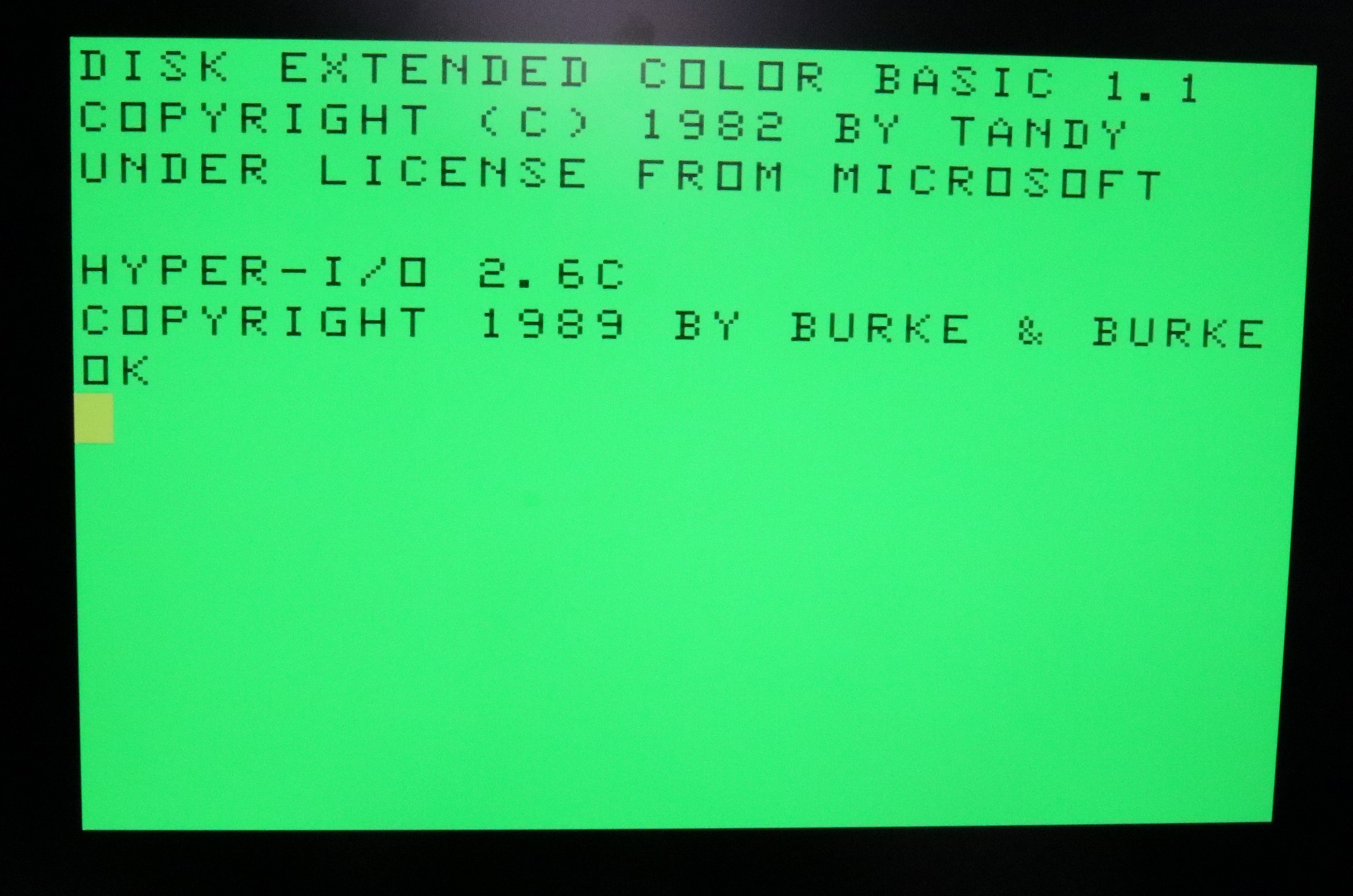
Running `RUN”HYPERIO”` from floppy on every boot gets old. Hyper-I/O has a `SAVESYS` program that snapshots the running, configured system into a ROM image, and Burke & Burke intended you to burn that to an EPROM and put it in the floppy controller in place of the Disk BASIC ROM. The image is 15.5K, because it contains a patched copy of Disk BASIC plus the hard disk driver.
My first thought was that the WD controller already has a ROM socket on it, wired to the coco’s CTS line, so why not put the image there? I wrote a program to scramble the image to match the inverted address lines, burned it to a 27128, set the jumpers according to a jumper table I found on the web, and it did not work at all. It turns out the jumper table was wrong. It described W5 on the WD1002A-WX1 as selecting between a 16K and a 32K ROM. What W5 actually selects is between a 2716 and a 2732/2764, and the socket has pin 26, which would be A13 on a 27128, tied to +5V. The socket is 8K, period.
What I ended up doing was putting the image on my multicart, which serves a full 16K from flash and can sit in any slot of the Multi-Pak. That mostly worked, in that the coco booted straight into Hyper-I/O, but then it immediately printed `?FC ERROR IN 0` and the hard disk was nowhere to be found. Disassembling the startup code turned up the reason. Hyper-I/O does a `LDA #$FF / STA $FF7F` during initialization, which sets both halves of the Multi-Pak’s slot register to slot 4. Burke & Burke could get away with that because their ROM was in the floppy controller, and the floppy controller was in slot 4, so the write changed nothing. With the ROM in a different slot than the floppy controller, that one instruction switches the ROM out from under the running code and you end up in plain Disk BASIC with no hard disk driver. Changing that one byte to point the CTS half of the register at the multicart’s slot fixed it, and now the coco powers up directly into Hyper-I/O with the hard disk online.
Revising and creating V2
The ROM size limitation on the WD controller left me wanting a solution where I could put a 27C128 on the CoCo XT board itself, so I designed a second version of the board with a socket for one. It’s wired straight to the coco’s unscrambled address lines, so the SAVESYS image goes in as-is, and a jumper selects whether CTS goes to the onboard EPROM or out to the WD controller’s socket like before. Since the ROM is then in the same slot as the hard disk rather than a third slot, the `$FF7F` problem above doesn’t apply either. I also tidied up the jumper to bypass the Dallas if you don’t want to use it, so that it connects what I believe are the right pins this time, and made the Q-to-CART connection a jumper instead of a trace.
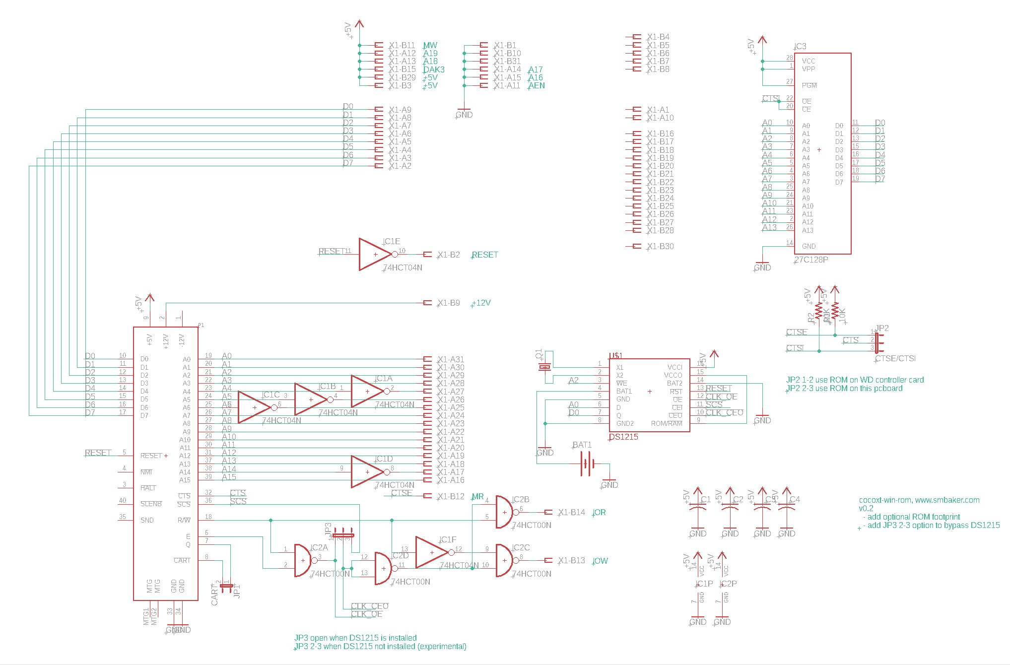
I haven’t built the V2 board yet, so treat it as untested until I do.
Resources
The schematics and Gerbers for both board revisions, along with a much longer set of notes on the software side, are in my GitHub repo at https://github.com/sbelectronics/coco/tree/master/cocoxt. The Burke & Burke software and manuals are on the Color Computer Archive; the notes in the repo say exactly which files you need and where to find them.
