
In this blog post, I build an HDMI adapter for my TRS-80 Color Computer 2
Background
About five years ago I bought a new-in-box CoCo 2 from eBay and made a few improvements. One of the improvements I intended to add was a CoCoVGA. It was sold out. I was added to the waitlist, but my name never came up. There have been other products, such as the CocoDV, but that too was sold out when I wanted to buy one.
Both the CocoDV and CocoVGA are proper digital solutions that tap the 6847 directly, not analog converters. My problem with them was availability, not approach. CoCoVGA outputs VGA; CocoDV is HDMI, but I couldn’t get one. What I wanted was true pixel-perfect HDMI, an open source design that anyone can build, and commonly available parts that someone with through-hole skills can install — at a bill of materials of roughly $30 – $50: about $15 – $30 for the Tang Nano, $5 for the PCB, and $10 for the level shifters, ADC, sockets, and passives. So I made my own!
This project — complete with Gerbers, source code, schematics, and firmware — can be found in my GitHub repo at https://github.com/sbelectronics/coco-hdmi.
Compatibility
I only have one CoCo, and it’s a Korean-made version with the horizontal RF modulator and the non-T1 6847. Because I only have one machine, I can’t say for certain whether this project will work on yours. At the very least, alternative spins of the interposer may be necessary to accommodate different motherboard layouts.
Some machines — particularly Korean-built “CoCo 2B” units — shipped with the MC6847T1 instead, which has true lowercase. The T1 is a genuinely different chip: DD0–DD5 arrive on reversed socket pins, and it has no A/S or INV pins because those functions moved into the data byte. There is a jumper on the board to select the T1 character set, and the data path works in simulation, but I have no T1 machine to test on and I do not consider T1 support verified. Expect at minimum that characters which should appear in inverse video will come out as lowercase glyphs instead, since the T1’s character ROM uses that data bit as a font-bank select rather than an invert.
This will not work with a CoCo 3. Not at all. Different video chip.
The interposer
The TRS-80 Color Computer, versions 1 and 2, uses an MC6847 IC to generate video. The 6847 scans display memory and sends a video signal to an RF modulator that puts the picture onto a TV channel, where it would have fed your 1980s-era TV. Unfortunately, we don’t really use CRTs anymore, and modern LCDs frequently don’t support RF or even composite. So what we’ll do is add an interposer PCB that sits between the CoCo’s motherboard and the 6847. The interposer feeds a Tang Nano, which contains an FPGA and an HDMI connector.
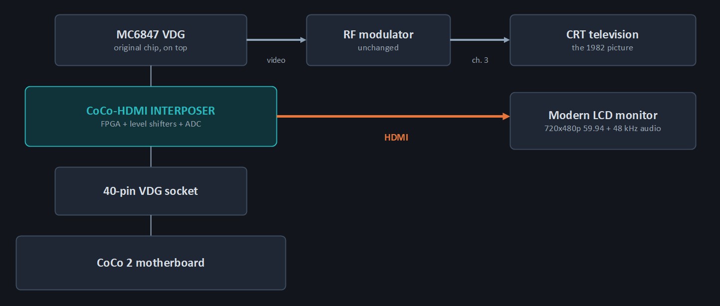
Importantly, the original video path keeps working. The real 6847 is not removed or replaced — it is reinstalled in a socket on top of the interposer and stays fully in circuit, still driving the RF modulator and still generating the HS and FS timing that the rest of the machine depends on. The FPGA only listens. Nothing on the motherboard changes behavior, and you can run the CRT and the HDMI monitor at the same time if you want to compare them.
Design
Design of the interposer was straightforward. The CoCo uses 5 V logic and the Tang Nano uses 3.3 V, so we need to perform level conversion. If we want to put sound on HDMI, we need an ADC to convert the analog sound to digital. A schematic is shown below.
You can find high-quality PDFs of the schematic in the GitHub repo.
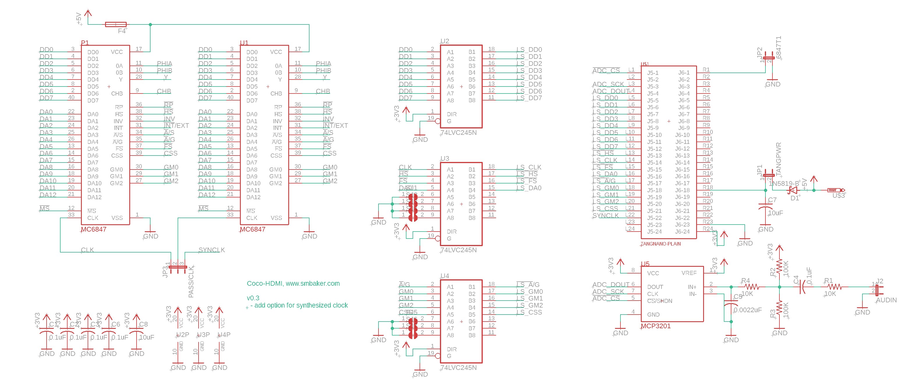
As you can see in the schematic, three 74LVC245 level converters are used. These are the most common level converters I have in my home lab, and even though they’re bidirectional, they can be permanently strapped unidirectional as shown — the CoCo-facing side can never drive. We take the eight data lines (DD0–DD7) from the CoCo’s 6847 socket, as well as CLK, HS, FS, and DA0. We also take several mode bits: A/G, GM0–GM2, and CSS. That’s seventeen signals in total, and from them we can determine the 6847’s operating mode and snoop on its timing as it reads from memory. The audio circuit uses an MCP3201.
Implementation
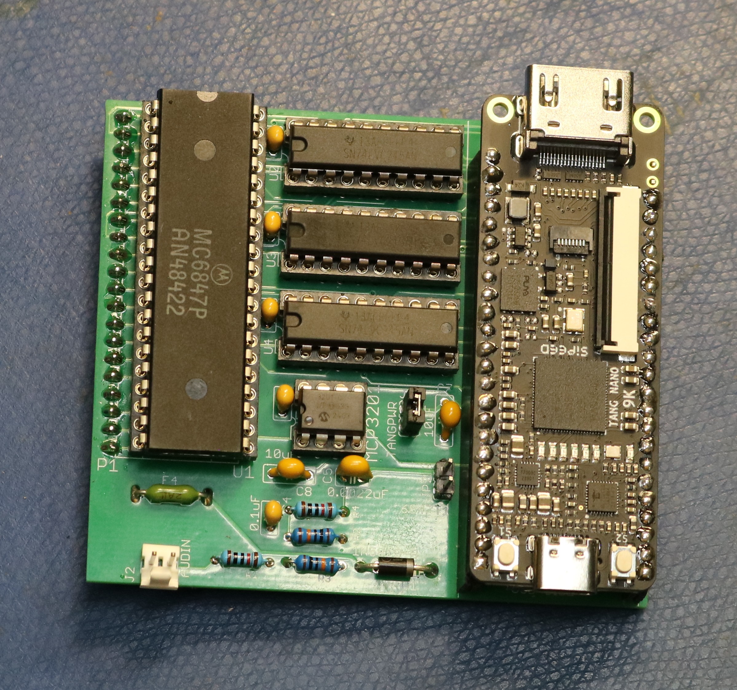
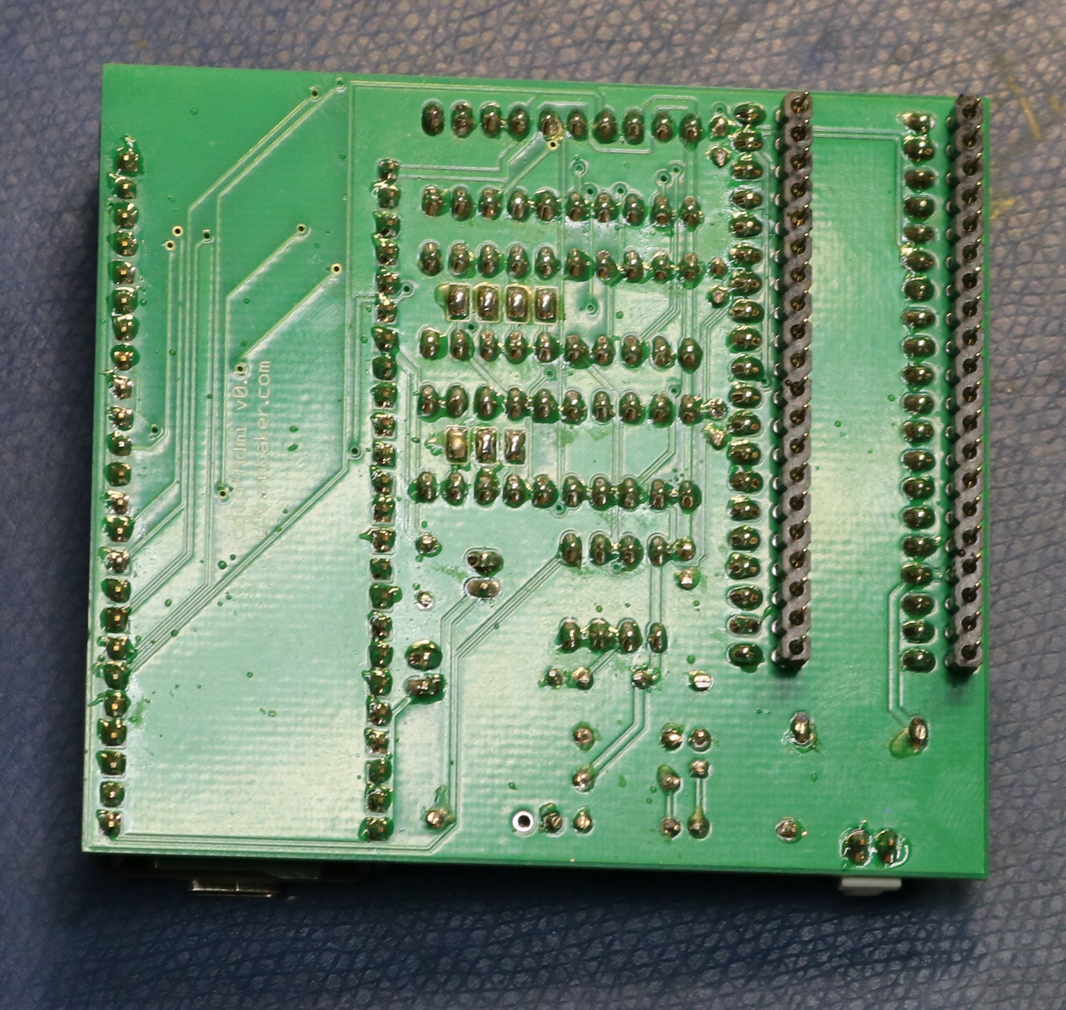
Below are a couple pictures of the circuit board:
Below is a picture of the board installed in my Coco-2:
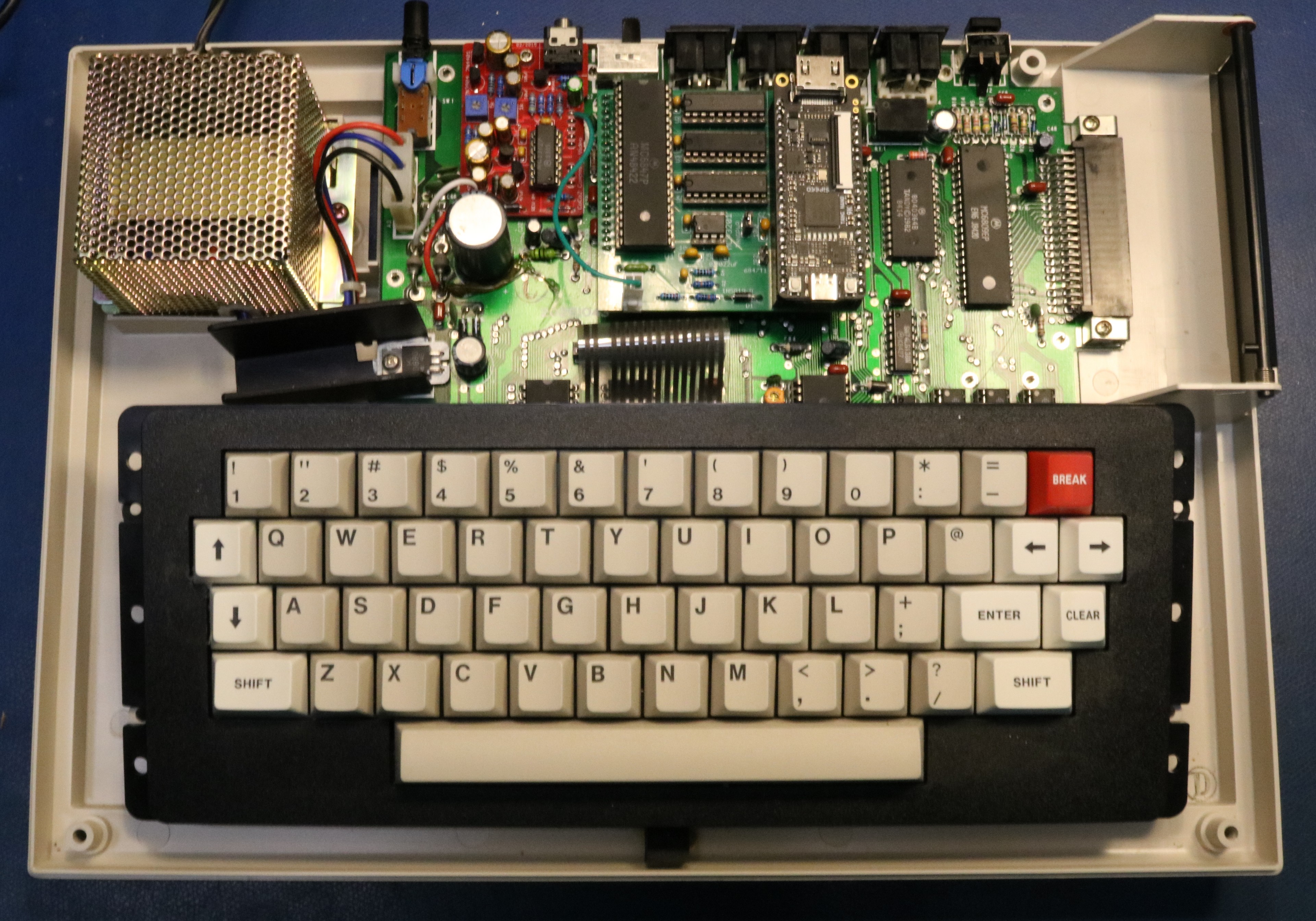
FPGA software
The obvious approach — fully reimplement the 6847 in the FPGA — is the hard one. The hard part of a 6847 isn’t the pixels, it’s the mode decode: four alphanumeric modes, two semigraphics modes with per-row bit shuffling, eight graphics modes with three different shift cadences, and the SG8/SG12/SG24 pseudo-modes that exist only because the SAM and the VDG can be told different things about the same screen.
So I don’t reimplement it. Instead the FPGA runs a second 6847 — an open source VHDL core from https://github.com/hoglet67/AtomGodilVideo — as a rendering engine, and feeds it the exact byte stream we watched the real chip consume. Bytes are recorded by fetch order, indexed by (line, cell), and served back in that same order. Because the replay core is the same logic as the real chip, it makes the same number of fetches per line in the same order, so replay is exact no matter what addresses the SAM actually drove or what tricks the software was playing. The SAM is never modeled at all.
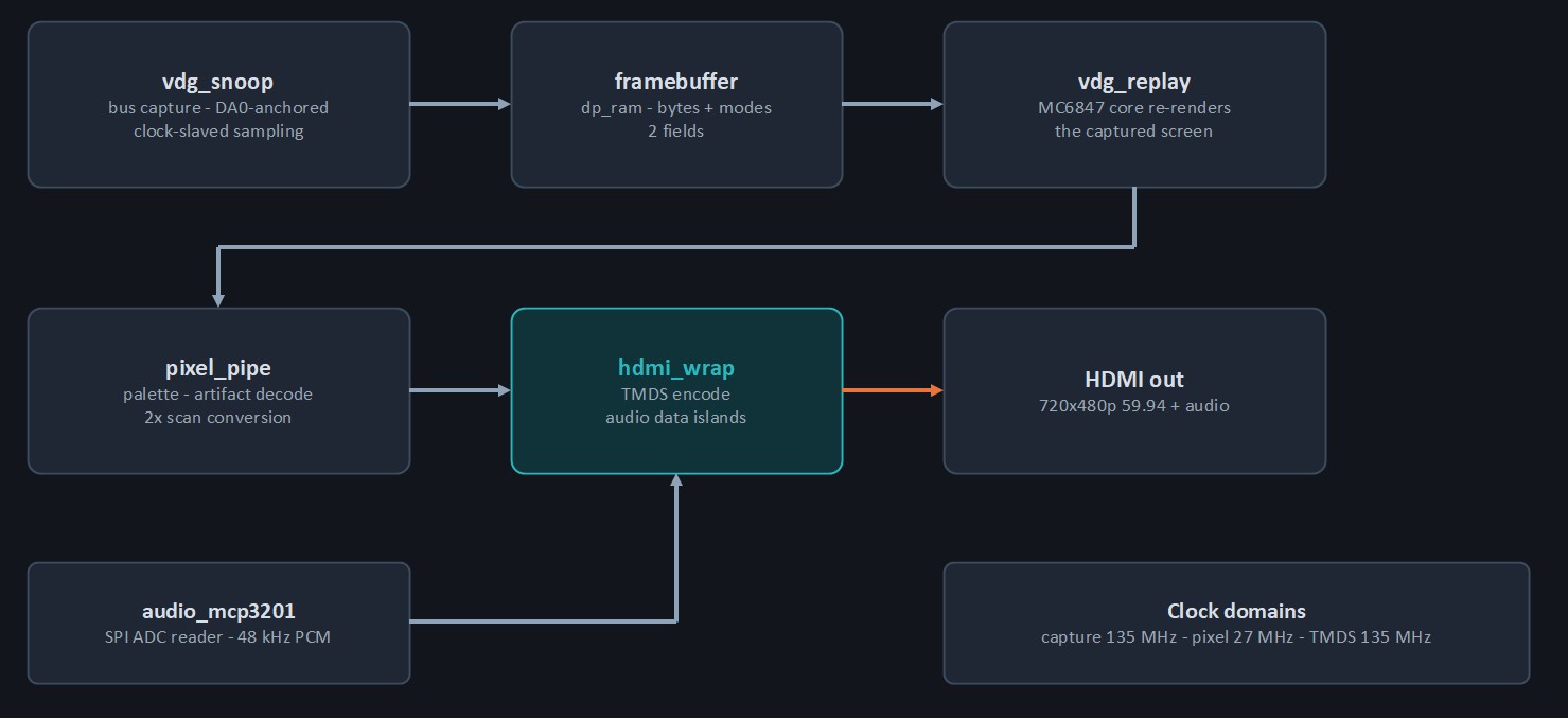
Finding the fetches is the interesting part. Rather than counting clocks from horizontal sync — which needs a calibration constant and breaks when the SAM stalls the video clock — the capture uses DA0, the VDG’s own address LSB, as the fetch strobe. It toggles once per fetch and goes static outside the active display area, so counting its edges self-gates to exactly the visible picture, with no tuning constants for the top border or the line start.
The display side runs at a bit-exact 27.000 MHz straight off the Tang Nano’s crystal, which is precisely the pixel clock for 720×480p59.94 — a mandatory HDMI format, so every monitor accepts it. The replay core is slaved to that raster rather than genlocked to the CoCo, which means no PLL chasing a 40-year-old clock and no framebuffer: a four-line buffer replaces it entirely. The small rate difference between the CoCo’s 59.92 Hz and HDMI’s 59.94 Hz is absorbed by rotating between four captured field buffers, so roughly once a minute a field is repeated or dropped, and no frame ever tears.
The last third of the work was none of the above. A 40-year-old NMOS bus seen through an interposer is genuinely nasty — the address lines legally churn for hundreds of nanoseconds around every fetch, the data byte survives only tens of nanoseconds past the clock edge rather than the datasheet’s 140, and the chip’s largest switching event couples runts onto the clock line itself. Nearly every filter and integrator in the capture engine exists because of a specific artifact I watched on the screen and then reproduced in simulation.
Claude Code assisted with the FPGA implementation.
Resources
Below are resources that may be helpful:
- GitHub repo — https://github.com/sbelectronics/coco-hdmi — containing the Gerbers, schematics, firmware, etc.
- MC6847 core — https://github.com/hoglet67/AtomGodilVideo

Great approach!