I interface an RGB Rotary Encoder to my Raspberry Pi:
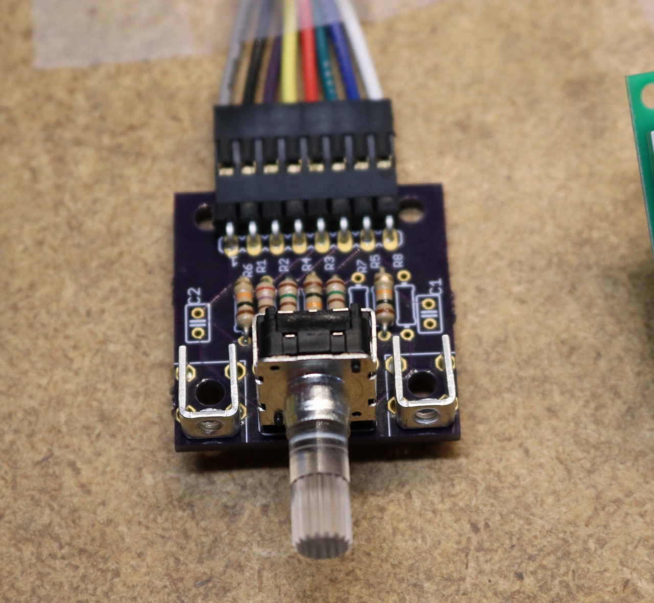
I really should have taken some more pictures… I suggest watching the video for most of the details — I actually whiteboarded the schematic and went through it. I did manage to design a breakout board, and it’s pictured below:
The Rotary Encoder is from SparkFun, com-10984. That’s the right-angle version. There’s also a vertical version, COM-10982, with a slightly different footprint.
The Rotary encoder has a total of 8 pins. Three of them are for the encoder itself:
- Common
- A
- B
The other 5 are for the LED and the switch:
- Red
- Switch
- Green
- Blue
- V+
There’s some code on the encoder demo checked into github at https://github.com/sbelectronics/pi-encoder. The thing was fairly easy to interface, and I made use of a library that Guy Carpenter had written as part of py-gaugette. Unfortunately, it’s not a gray-code encoder, but is a standard incremental quadrature encoder. You watch the A and B lines and depending on how they transition, you’re able to determine the direction and the number of steps that have turned. How the encoder works is explained in my video at the top of the page.
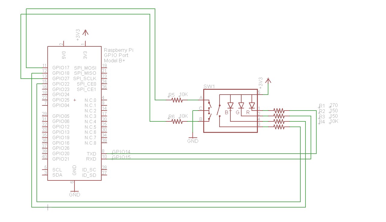
The LED has three elements for red, green, and blue respectively, and you can PWM them to get various shades of colors. The switch is a simple pushbutton — push in on the encoder shaft. This schematic shows which GPIO pins I connected it to on the pi:
I went on to use this encoder in my digital attenuator project.

