After building so many Nixie Tube Clocks from the Internet, I finally decided to design my own. My clock uses IN-12 Nixie Tubes and an 8-core Propeller Microcontroller. The Propeller may a be a bit of overkill for the task, but it’s the microcontroller that I’m most familiar with an is easy to program. A Dallas 1302 RTC chip is used for accurate timekeeping.
Design Choices
I had many choices of which Nixie Tubes to use, and I chose the IN-12 for several reasons. First of all, they’re very cheap. You can pick them up on ebay for around a buck a piece plus shipping. Second, they use pin sockets. I really hate having to solder tubes direct to the board, like in the IN-14s. Third, they’re a horizontal-facing tube as opposed to the upright tubes. I thought it would be fun to do some horizontal projects.
Designing the clock
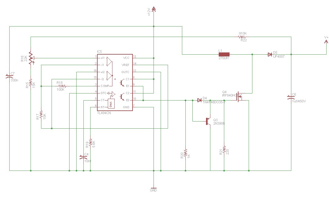
Let’s take a look at a few snippets of the schematic. The first is the high voltage power supply:
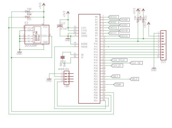
This is the same PSU that I’ve used elsewhere on the web site for other projects (including my dekatron projects). It’s based ont he power supply used in tubehobby’s clock. The TL494 forms a straightforward switching power supply. It’s an easy to build supply, and is very stable and easy to trim for the correct voltage. Next up is the microcontroller:
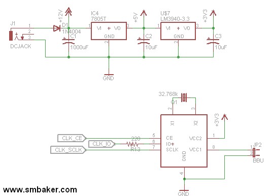
The microcontroller circuit is a very straightforward propeller design, if you’re familiar with the propeller. The 4-pin header is for in-circuit programming. The EEPROM is because the prop stores it’s program in external EEPROM rather than internally. The large header is for expansion. I put 10K pullup resistors on two of the pins on the expansion header in case I want to use them for buttons. Next let’s look at the low-voltage power supply and the DS1302:
The power supply uses a pair of linear regulators. The first regulates down to 5V (for the K155D drivers) and the second regulates the 5V down to 3.3V for the prop, eeprom, and dallas clock. The dallas clock is fairly stragithforward to connect. There’s three pins for control. It has its own crystal. I brought the BBU (battery backup) out to a header in case I want to install a battery at a later time. Next up let’s have a look at the Nixie Tubes and drivers:
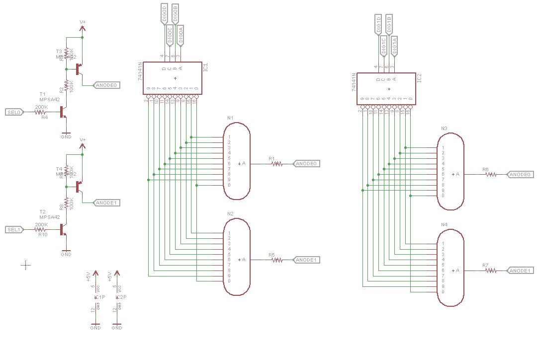
The tube schematic got scaled a little tiny to fit everything on the page. You can click it for a bigger picture (as with all the other schematics on this page). We have a total for four IN-12 tubes. The cathodes are controlled by K155D (similar to 74141) Nixie Tube Drivers. The K155D is a handy chip that takes a 4-bit BCD value and grounds the appropriate cathode to light up the digit for you. You’ll notice that each K155D is connected to two tubes. That’s so we can save a little bit of part count on the board and pin count on the MCU. The anodes are controlled by a pair of transistors, a MPSA42 and a MPSA92. This is called multiplexing. All four tubes aren’t on at the same time — we light them alternatively so fast that a human cannot tell.
To prevent ghosting, it’s important that you use a blanking interval. During the blanking interval, the anodes are turned off. Then during the display interval you turn on the appropriate cathodes (via BCD value to the K155D) and turn on one of the anodes.
I’ve left the anode resistors unmarked in the schematic. I used 10K in my clock. Finally, there’s one last bit in the schematic and it’s entirely optional:
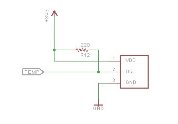
This is a Dallas 1822 thermometer. It’s on the board so I can repurpose the clock board as a nixie tube thermometer.
The Revision 1 Prototype
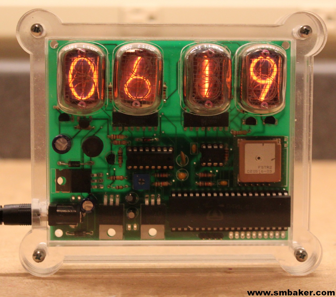
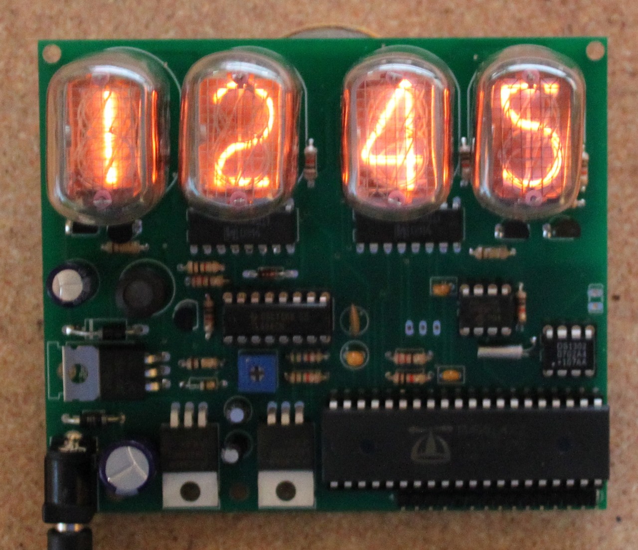
My first prototype is shown below.
Lessons Learned
First of all, my plan has always been to hook a GPS up to this clock so it can set itself. That’s one of the reasons for the expansion header, so there’s a few data pins available to connect a GPS module. I currently have a couple of Sparkfun GPS modules on order, an EM-406A and a UP501. The EM-406A is something I’ve used before. The disadvantage of it is that it requires 5 VDC power, and I didn’t leave a 5 V pin anywhere on the board. The UP501 I haven’t used. It fortunately uses 3.3V, so I’ll be able to use the power pins on the expansion header. In both cases, I wish I’d taken the time to lay out the proper pinout on the board for connecting the GPS modules. It’d be simpler than wiring up a custom cable to go to the expansion header.
I also put the power jack facing down. This is inconvenient if the clock were to sit upright on a desktop. A side-facing power jack probably would have been wiser. In a desktop-clock configuration, one will probably omit the on-board jack and wire a pigtail to a case-mounted jack. A pin header for that purpose would have been handy.
I also made the holes for the nixie socket pins too small. They fit one style of pin (available from ebay sellers sparkletube and unusual_electronics), but I really prefer a different style (available from ebay seller urals). I had thought I chose a hole large enough to accommodate either side of pin. Either the dimensional drawing was off, or I forgot to account for the thickness of the hole on the circuit board.
I also didn’t include a “:” between the hours and minutes digits. I’m of somewhat mixed feelings about colon indicators. However, if I desire the board to be something that third parties may be interested in, then it may be valuable to add neon bulbs. You’ll notice I left off the under-board mounted LEDs that so many nixie kits seem to come with. I don’t think they would look that good on an IN-12, and I’m not all that fond of mixing the display technology.
Thus, the next board revision will have: 1) at least one pin header for a GPS, 2) a side-facing power jack and probably a pin header for it, 3) a hole that will accommodate either nixie pin, and 4) a pin header on board for 5V.
The Code
Let’s take a look at a few code fragments. This first one handles multiplexing of the display. First of all, I’m not entirely sure I’m doing this right. I chose a 250us blakning interval and a 1ms display interval. I output “11” to the K155D to turn off the cathodes (there is no “11” digit).
' in12clockdisplay.spin
' This module handles multiplexing the display

VAR
    long hours
    long minutes
    long myStack[12]

PUB Start
    cognew(ShowValue, @myStack)

PUB SetMinutes(x)
   minutes := x

PUB SetHours(x)
   hours := x

PRI ShowValue
    dira[SEL1] ~~
    dira[SEL2] ~~
    dira[DIG0..DIG0D] ~~
    dira[DIG1..DIG1D] ~~
    repeat
        ' first let's do the hours

        ' blank
        outa[sel1] := 0
        outa[sel2] := 0

        waitcnt(clkfreq / BLK + cnt)   ' 250us

        ' display
        outa[dig0D..dig0] := (hours / 10)
        outa[dig1D..dig1] := (minutes / 10)
        outa[sel1]:= 1

        waitcnt(clkfreq / DSP + cnt)    ' 1ms

        ' blank
        outa[sel1] := 0
        outa[sel2] := 0

       waitcnt(clkfreq / BLK + cnt)

       ' display
       outa[dig0D..dig0] := (hours // 10)
       outa[dig1D..dig1] := (minutes // 10)
       outa[sel2] := 1

      waitcnt(clkfreq / DSP + cnt)
Next is the main module for the clock. It’s still in the prototype stage. I’m not supporting the GPS or the buttons yet. I’ve hardcoded the starting time (yes, every time I recompile the clock, or power it down, I have to change the start time).
VAR
    long hours, minutes, seconds

OBJ
    display : "in12clockdisplay"
    rtc : "ds1302"

PUB main
    display.Start

    rtc.init(16,18,17)
    rtc.config
    rtc.setDateTime(1, 17, 07, 3, 22, 21, 0)

    clockloop

PUB clockloop | lastMinutes
    lastMinutes := 61
    repeat
        rtc.readTime(@hours, @minutes, @seconds)
        if minutes <> lastMinutes
            lastMinutes := minutes
            display.SetMinutes(minutes)
            display.SetHours(hours)
        waitcnt(clkfreq/20 + cnt)
Using a GPS module for automatic time setting
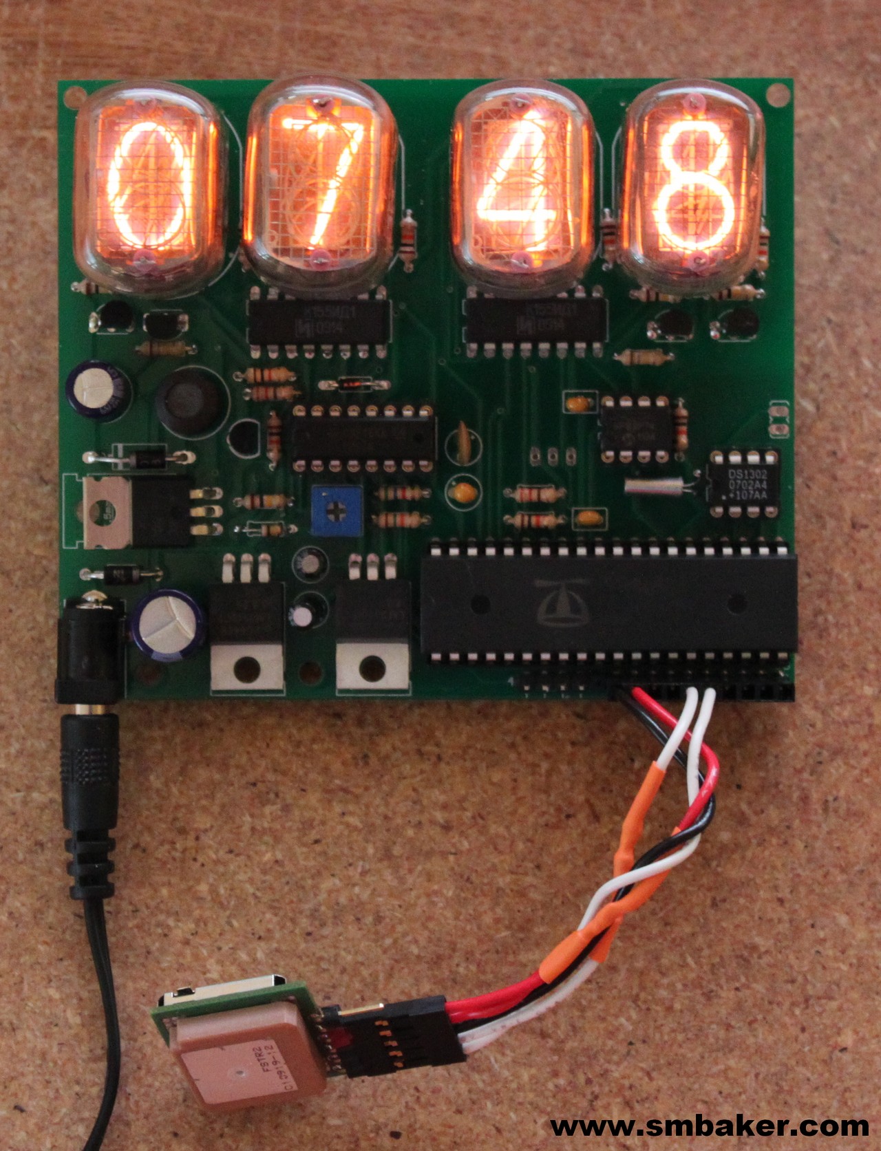
I hate setting clocks, so the next task was to GPS-enable the clock. To do this I chose the UP501 GPS module from Sparkfun. There’s several advantages to this module. First, it’s fairly small. Second, it uses 3.3V instead of the 5V that many other modules use. Here’s a picture of the GPS module connected to the clock’s expansion port:
The next revision of the board will have a footprint and connector on-board for the UP501, so we can get rid of that ugly cable. Now let’s have a look at the code:
CON
  _clkmode = xtal1 + pll16x
  _xinfreq = 5_000_000

VAR
  long hours, minutes, seconds, tzone

OBJ
  display : "in12clockdisplay"
  rtc : "ds1302"
  gps : "gpsdriver"

PUB main
    tzone := -7 ' pacific daylight offset from GMT
    hours := 0
    minutes := 0
    seconds := 0

    display.Start

    gps_clockloop

PUB gps_clockloop | lastMinutes, t, gpsPointer
    gpsPointer := gps.start(10, 0, 9600)
    repeat
        ' we don't really need these in a 4-digit clock
        t := long[gpsPointer+12]
        seconds := ((t>>16) & $FF - 48) * 10 + ((t>>8) & $FF - 48)

        t := long[gpsPointer+8]
        minutes := ((t>>8) & $FF - 48) * 10 + (t & $FF) - 48

        hours := ((t>>24) - 48) * 10 + ((t>>16) & $FF) - 48

        ' adjust time zone
        hours := hours + tzone
        if (hours < 0)             hours := hours + 24         ' convert from 24H to 12H         if (hours > 12)
            hours := hours - 12

        display.SetHours(hours)
        display.SetMinutes(minutes)

        waitcnt(clkfreq/20 + cnt)
The gpsdriver module came from the parallax object exchange (OBEX) and includes code for decoding NMEA GPS data over the serial port. It’s simply a matter of starting this module and collecting the data from it. The gpsdriver module stores its timestamps in a pair of longs. They’re encoded as ASCII digits shifted into the long. For example, the first long contains the first hour digit in the high 8 bits, then the second hour digit, then the first minute digit, then the second minute digit. We shift them out and subtract 48 (“0” is 48 in ASCII).
The nice thing about this is we don’t even need the DS1302 anymore if the GPS option is installed. The GPS automatically outputs the GPRMC packet once per second, and this packet includes the current time and date. For now, I’ve hardcoded the timezone to -7 (pacific daylight). At some point I’ll revise this to automatically compute DST based on the current date.
Designing the case
I designed an acrylic case using inkscape. The inkscape template looks roughly like this:
Above are the three basic shapes that make up the case. They are a top, a bottom, and a side. It takes three of the side pieces to make up a full side. I sent my template off to a company called “ponoko” and a couple weeks later I had a laser-cut sheet of acrylic sitting at my doorstep. Generally it worked out pretty well, although I mistakenly used a measurement that was off by 0.005 on the height of the PCB, and as such the PCB had to take a little visit to the grinder (careful not to cut off any traces).
The Revision 2 Prototype
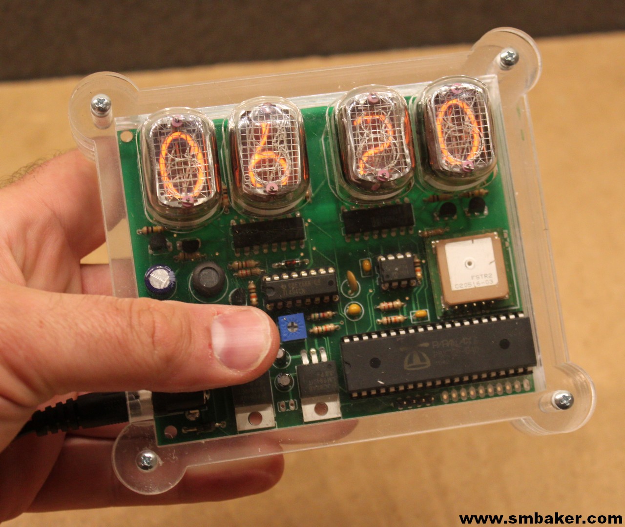
Here is another picture of the revision 2 prototype, along with my hand shown for scale:
The revision 2 prototype is a fully functional complete clock. It includes the UP501 GPS module from sparkfun instead of the DS1302 clock, so the clock is always set to the correct time. It’s installed in my ponoko-manufactured acyrlic case. It’s going somewhere in my house, probably on my desk.
The revision 2 video
While assembling the revision 2 clock, I made this video. It shows me soldering the components and giving a few tips regarding things like soldering the Nixie Tube pins. It also shows assembly of the case, testing, etc.

Very nice project, man!
I start playing with nixie clocks too, it is a very rewarding project =)
They just look so neat.
I am particularly interested on the acrylic case. Do you mind sharing how much $$ it costs to make one like yours?
The ponoko order came to about $85. That included cases for 3 other projects as well (though they were generally smaller than the nixie clock case). My guess would be the case probably cost about $30 of the total order. The cost of making the case depends greatly on the thickness of the material. It’s not the material itself that’s expensive, but the laser time on thicker material is longer than on thinner material. I used 5.6mm material throughout. I probably could have got by with 3.0mm material for the top and bottom and saved a few bucks.
I think I will give it a try =)
I used a cigar box for my clock. But is far from OK!
Now I am converting it to a multimeter (http://www.youtube.com/watch?v=NwBKmTFYuQk)
I have one more question if you do not mind: I did not buy gps unit so far because I am afraid is not going to work inside the house. Did you have any problems with yours regarding this matter?
I haven’t had any trouble using the GPS indoors. The room where I demo’d it was right in the middle of the house and full of lots of noisy devices (computers, routers, multiple HV nixie projects, etc). I’m surprised how well the GPS is able to attain signal. It’s really a lot better than the older GPS units that I remember.
I was reading your page about the IN12 clock build, and I am sort of in the same position as you. I have built a few clocks, but they are not what I am really looking for.
I am curious if you are planning on offering the boards and chips available as a kit. You seem to have done everything right in regards to designing the board, and if you are offering the boards, I am interested in purchasing one. Thanks for any info.
Ron
…Semper Fidelis…
Just stumbled across this site…
Wondering if the “final” code for this project is available? This looks like something I might want to take on… but would love to see the complete code for the project, rather than having to invent some of it for the first time.
THANKS.
Would also like to be able to download the full code, and board design (or even better, be able to purchase a board). Looks like an interesting project, even 8 years after you published it.