There’s something fun about using period tools to work on old radios:
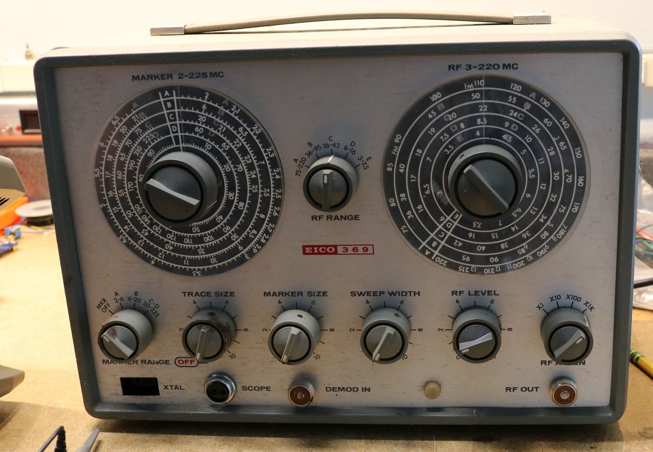
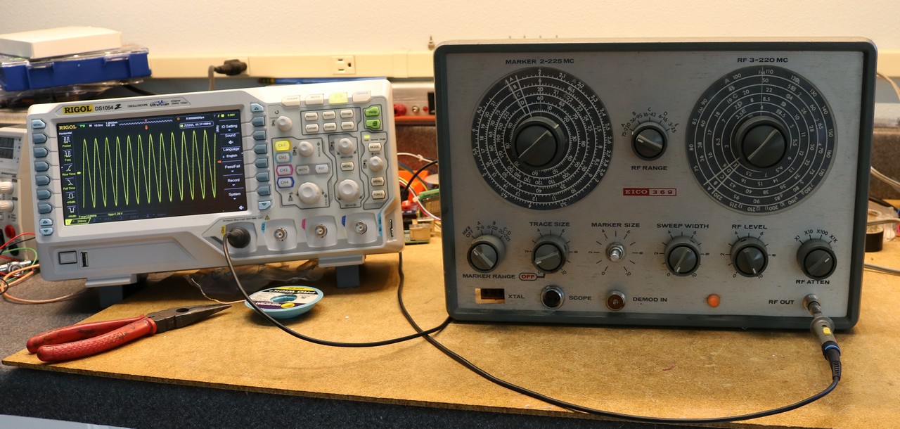
This is my second tube RF generator, and my fifth RF generator overall. Why did I buy this one? I think having an old-school RF sweep generator is both fun, and it’s the type of that the instructions that tell you how to align the old radios expect you to be using. Let’s start with some pictures of the Eico 369:
Let’s take a small tour of the controls. The dial on the left is the marker osciallator frequency. The marker oscillator puts a blip on the output so you can see a specfic spot during the sweep. My video makes it obvious how this works, and I’ll try to describe it below in text as well. The dial on the right is the sweep oscillator center frequency. Between the two big dials is the range of the sweep oscillator. It’s usable from 3Mhz all the way up to 220Mhz.
Starting with the small dials, working left to right, the first is the marker range. It allows you to select the range of the marker oscillator, from 2Mhz up to 225Mhz. The next is the trace size, which controls how large the demodulated swept trace is on your scope. Next is marker size, which determines how big the marker blip is. Sweep width lets you control how wide the sweep is. The final two are an RF pot and an RF stepped attenuator.
You can see it has the weird microphone connector RF probe jacks that are typical of 50s and 60s RF test gear. One of the first things I did was replace those with BNC jacks.
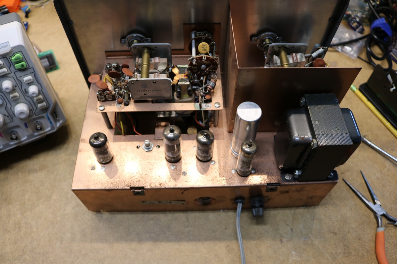
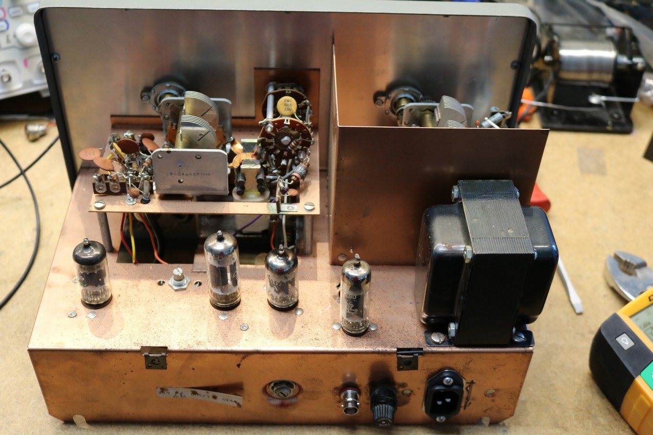
Now for some inside pictures. Let’s start with a view from the top:
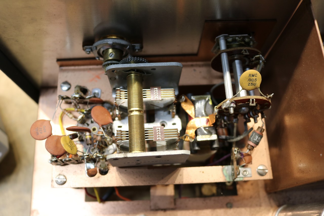
Among the tubes in the above picture is an aluminum cap — that’s the main filter cap. I ended up replacing it because I generally replace all really old electrolytics, even tough it didn’t test bad. Next up is a picture of the Sweep Oscillator Variable Capacitor:
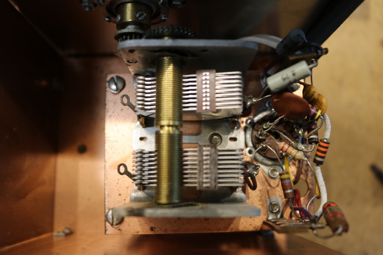
Next up is the Marker Oscillator Variable Capacitor:
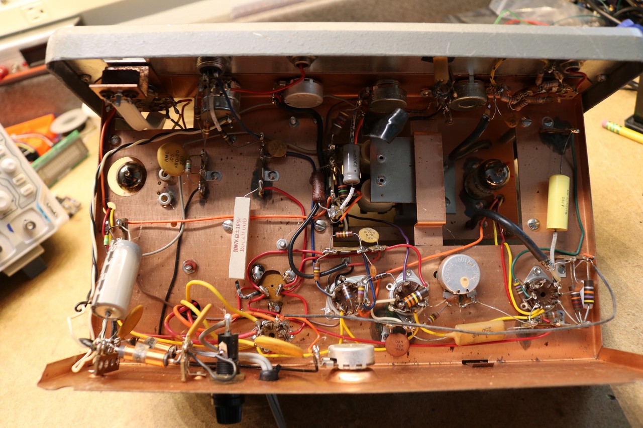
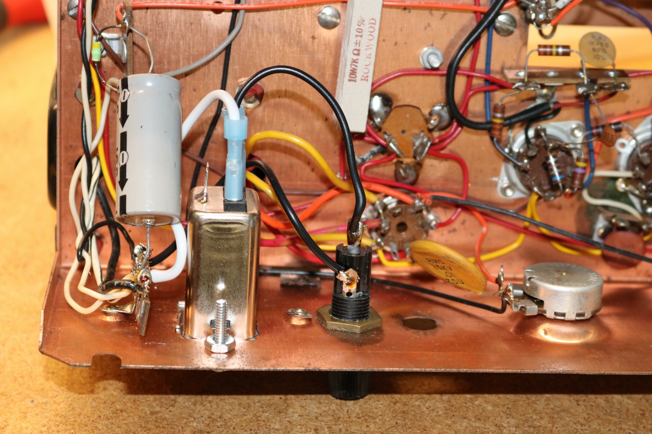
Here is a picture of the underside of the Eico 369:
The very first modification I did was to replace the RF output jack with a BNC jack, then I verified I was getting an RF signal using my Rigol DS1054Z:
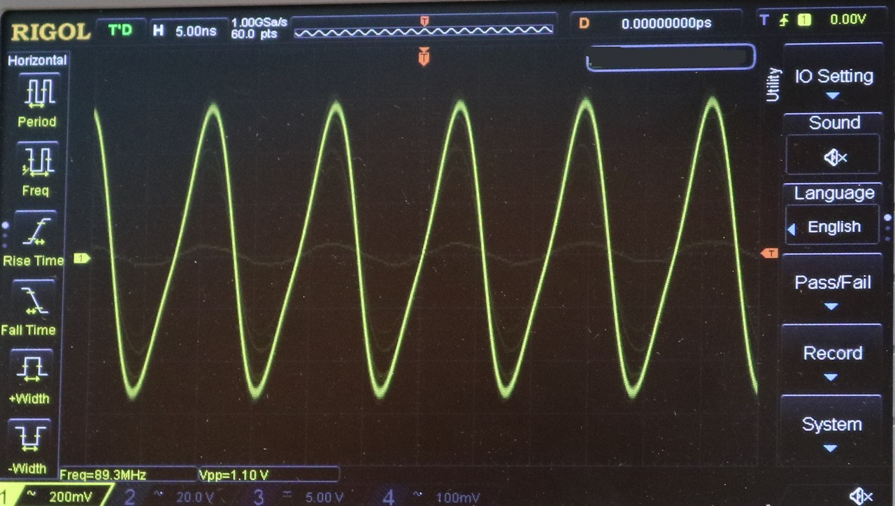
Here’s a closeup of the waveform at 89Mhz:
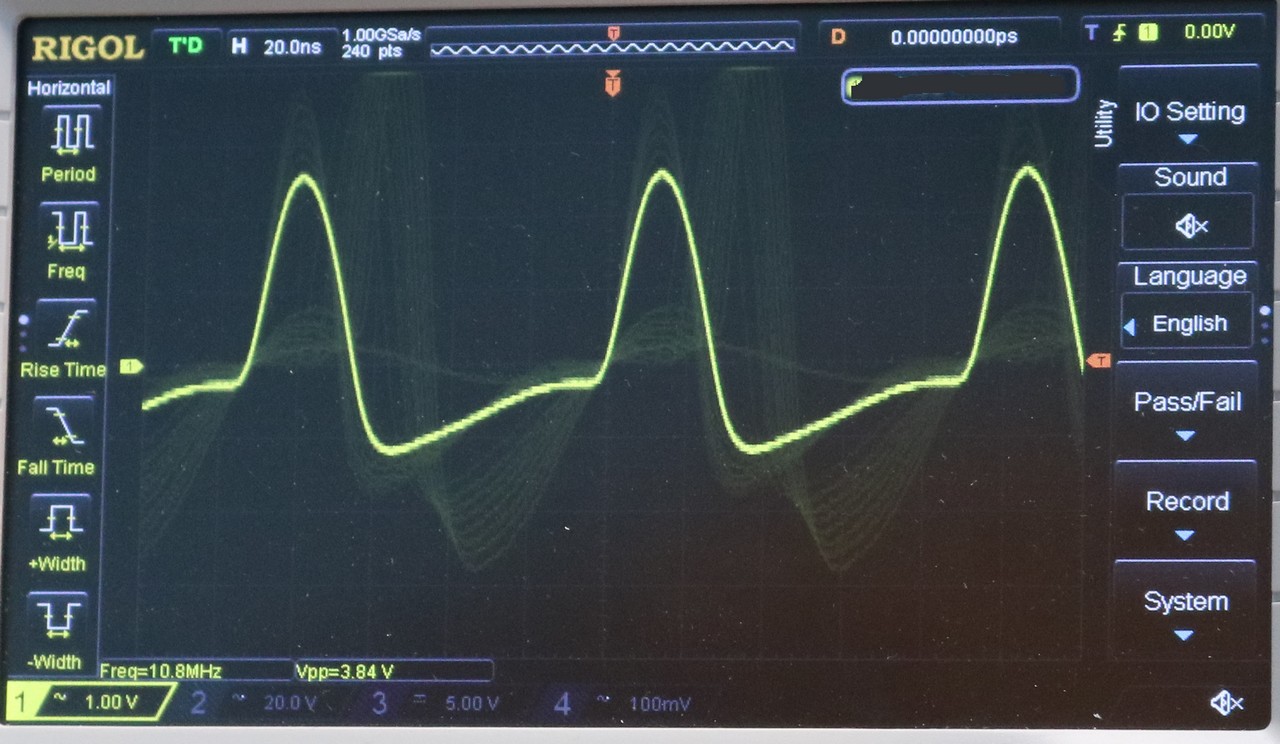
… and here’s one at 10.8 Mhz:
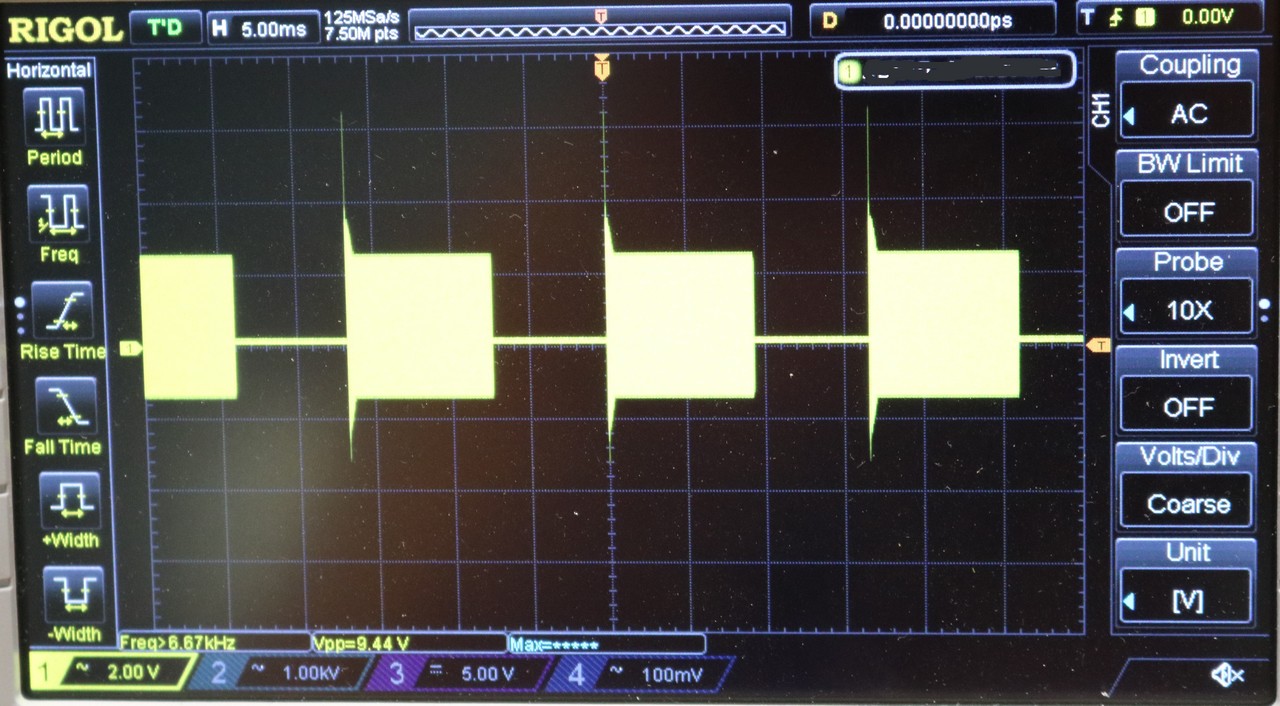
You’ll notice the waveform is not quite sinusoidal. That doesn’t seem to be that uncommon for RF generators of this era and design. However, you’ll also notice if you look closely that there’s a bunch of other dimmer waveforms. This intially had me quite concerned and I went to the antique radio forum for clarification. The Eico 369 has a blanking circuit, that switches the oscillator on and off at 60 Hz, and every time it switches on, it’ll generate a bit of noise. This noise results in those dim waveforms. It looks nasty when viewing the raw RF output, but when you’re actually sweeping it’s not bad, and it’s obvious that the noise is all concentrated at the start of the sweep.
Backing the scope way out, so we can see several blanking intervals, we can understand where the noise is:
Another modification I performed was to remove the old EMI/RFI filtering and old power cord and replace it with a modern EIC receptacle, so I can use any old computer power cord I have laying around:
I also added a BNC jack onto the back that I can use to read the exact freqeuncy of the marker oscillator using my frequency counter:
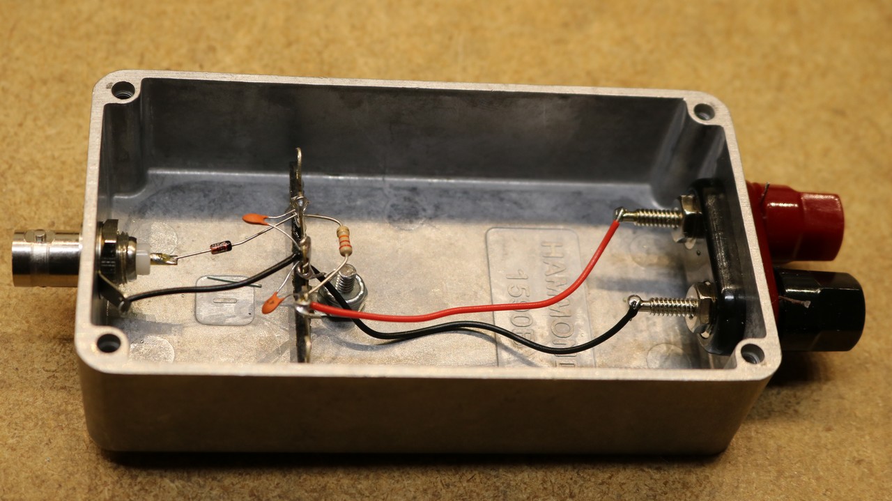
For testing and calibration, the manual suggests you make a ‘broadband detector’. It a germanium diode (I used a 1N60), some caps, and a resistor:
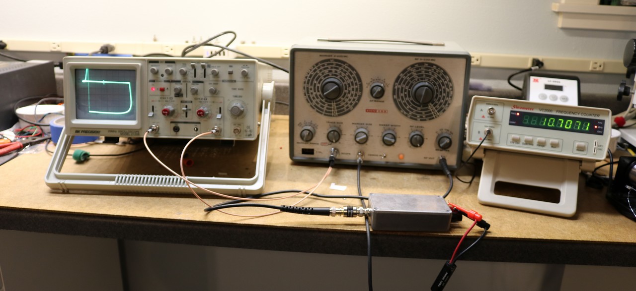
Now that I’ve made the broadband detector, I can finally perform a test sweep. I connect it to my old BK Precision 2120B oscilloscope.
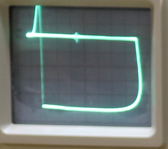
Here’s a close-up:
So let’s discuss what we’re seeing above. The topmost horizontal line is the sweep, and it sweeps from left to right. The blip you see right in the middle is the marker oscillator, which is set to 10.7 Mhz. The line is flat because the broadband detector has a flat response curve — it attenuates all signals equally. On the right hand of the display, you scan see where the Eico 369 blanks, and drops the output down to zero. It then sweeps along the zero line back to the left. The blanking circuit disengages, and we get that big noisy spike that you saw before, and then the sweep begins over again.
All things considered, for a piece of vintage test equipment, this thing is pretty fun to play with, and is a useful addition to the bench.
