Rebuild an IHI RHB5 Turbo and add a Carbon Seal
This article is going to describe how to rebuild an IHI RHB5 turbocharger and add a carbon seal to it.
The difference between dynamic and carbon seals:
- There are two different types of seals in turbochargers: dynamic (aka piston) and carbon (aka positive). The carbon seal is suitable for either blow-through or draw-through applications. Dynamic seals are suitable for blow-through only! I repeat, you cannot use a dynamic seal on a draw-through turbo system. This is important. Ideally, if you want to build a draw-through turbo, you would select a turbocharger that came with a carbon seal already in it, and save yourself a lot of headaches later. Unfortunately, carbon seal turbos are a rarity, because the newer dynamic seal is more efficient, and well suitable to the fuel injected engines that are used these days. So, the moral of the story is if you want a draw-through setup, either a) find a turbo with a carbon seal, or b) rebuild your turbo and convert it to carbon seal.
Parts identification:
- Let’s start out by identifying some parts, so we make sure we know what kind of seals we have. The first picture below is of a dynamic (or “piston”) seal and the seal plate that goes with it:
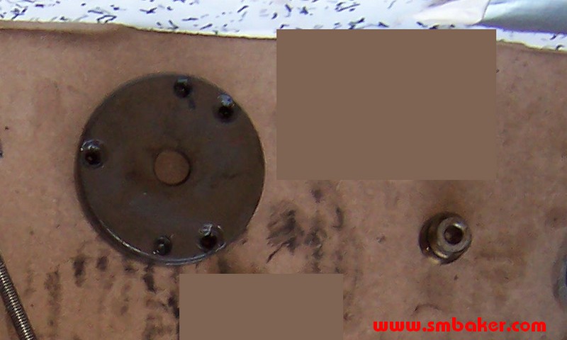 |
DYNAMIC(or PISTON)
seal |
The dynamic seal is composed of two parts. The seal plate (the big flat round thing) and the piston (the little cylindrical thing). The piston should contain two piston rings. They’re little split rings just like on a piston in a motor
The next picture below is of a carbon seal plate and thrust collar:
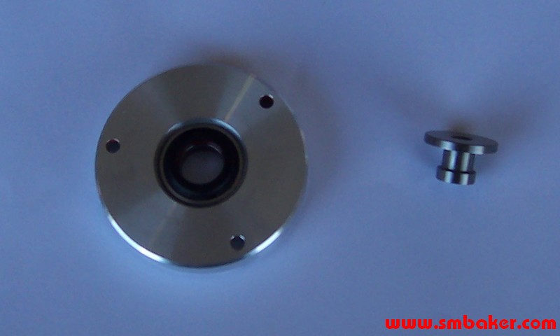 |
CARBON(or POSITIVE)
seal |
The carbon seal has a special seal plate. The seal plate contains a spring-loaded carbon seal (the black part). The carbon seal configuration replaces the piston with a thrust collar. The large flattened surface on the thrust collar should mate perfectly with the black part of the seal plate.
Turbo Disassembly
- The key to a successful turbo reassembly is marking everything during disassembly. Make sure to do this as you go along. Before disassembling the compressor and turbine housings, make them with either a pen or a scribe a little line with a scribing tool. I recommend the scribe rather than the pen, because you will be hitting lots of stuff with parts cleaner that likes to take off pen marks.Step 1: Remove the oil inlet banjo fitting and the water banjo fittings. Life’s just easier with them gone. Personally, I left the oil drain fitting attached.
Step 2: Remove the turbine housing. It is held on by four bolts. Two of the little bastards don’t have enough clearance between them and the water fittings to pull them all the way out until after you’ve got the turbing housing loose. Be careful with these bolts as they may be stuck in pretty damn hard. Personally I broke one off during my disassembly, which led to removing it with an easy-out, which then turned into an adventure in how to remove a broken out easy out, which ended up with me redrilling and retapping the housing. what a mess…
The turbine housing will most likely be stuck pretty good to the center section. Once you have the four bolts out, you’ll most likely have to do some tapping with a (rubber) hammer. I also gave mine some heat with a small butane torch to encourage seperation. If you use heat, only heat the turbine housing, not the center section. You’re trying to get the turbine housing to expand (not the center section!).
[Note: The reason we remove the turbine housing BEFORE the compressor housing is that the turbine housing is the more difficult of the two to remove. You want to leave the compressor side nice and protected while you’re beating on and cursing at the stuck turbine housing….]
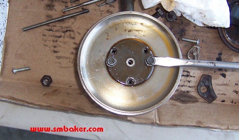
Below is a picture of the center section with the turbine housing removed:
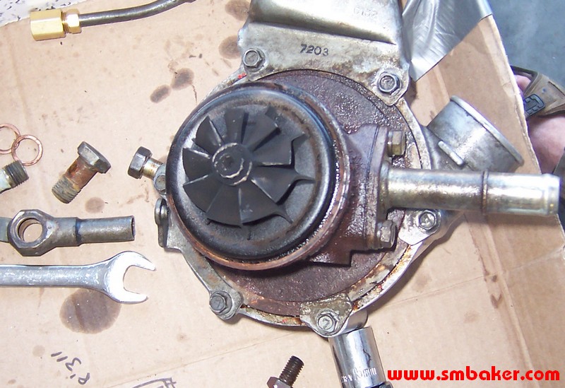
Step #3: Remove the compressor housing. This is compartively simple in comparison to the turbine housing. There’s just a bunch of little bolts around the permimeter of the compressor housing to remove. The turbine housing may be siliconed in, and might be a little hard to remove. Once that’s done, we should be left with just the center housing:
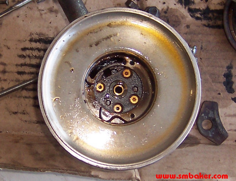
 |
Here is a picture of the center section.Note that this picture shows the nut loosened — don’t do that yet! You need to mark the positions of the rotating parts first (see next step) |
Step #4: Mark rotating part positions. This is critical if you intend to reassemble your turbo without balancing it first. The turbine shaft is balanced to a very precise standard. If you take it apart without marking it first, you will be screwed unless you intend to reblance it. You need to mark the position of the compressor wheel relative to the turbine wheel. There’s several ways you can do this. You can either mark them with a pen, or (lightly) scribe a line into them. The problem with the pen is that you will be dumping them in solvent to clean them up, and the solvent will take off the pen marks. Someone else’s FAQ recommended against scribing the parts, but personally, I found mine were already scribed by the previous rebuilder so it must be at least a fairly common practice.
The critical thing is that you must be able to line up the compressor wheel with the turbine wheel. Once you take the nut loose, the compressor wheel will be free to turn.
Also take a look at your nut. It may be ground on one side for balance. If this is the case, you might also want to mark the alignment of the nut to the rest of the parts. Presumably, you will be torquing the nut to spec later on, but in my opinion marking these parts it important enough that you really can’t mark too many things.
Step #5: Remove the compressor nut. It has a reverse thread on it. So make sure to turn the nut backwards from the way you’d normally remove a nut. Otherwise it’ll just get tighter and tighter and you’ll get more and more confused.
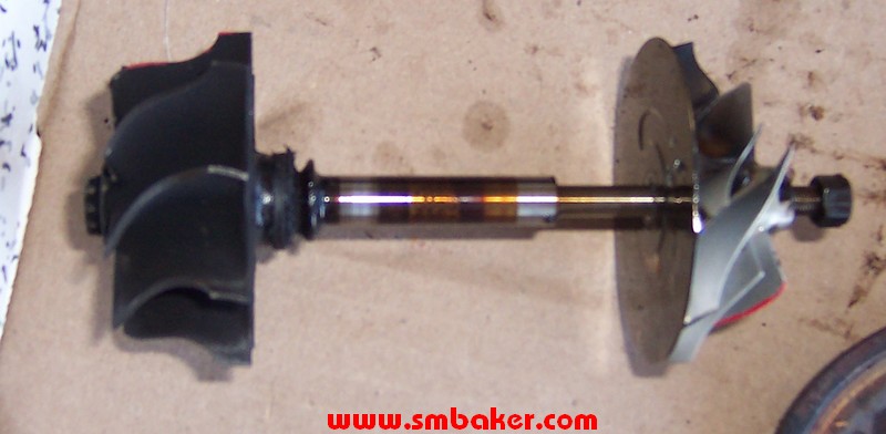
Step #6: Remove the compressor wheel and turbine shaft. Dump them in some solvent. Here is a picture of a removed turbine shaft, compressor wheel, and nut:
Step #7: Remove the seal. The seal is held on by three torx screws. Once you remove the screws, it will most likely be stuck on because the previous builder will have siliconed it in there. You can remove it by threading some bolts into the two other holes in the seal plate and prying with a screwdriver. Be careful not to damage anything while prying:
Step #8: Remove the thrust plate. This is held on by four more torx screws. It shouldn’t be siliconed in, and therefore shouldn’t be as hard to pull as the seal plate was. Personally. I tapped on the backside of it (very gently) by inserting a rod at an angle through the turbine side of the center section.
Step #9: Remove snap rings and bearings. The compressor-side bearing will come right out after you’ve removed the thrust plate. The turbine side bearing will need a snap ring pulled before you can remove it. Getting these snap rings out is difficult because they take very small snap ring pliers. I found a pair at sears that would do the job, but the tips were very fragile and easy to damage. You only need to get the one snap ring out to gain access to the turbine side bearing. You can leave the two center snap rings in.
Congratulations. You’ve taken an assembled turbocharger and converted it into a pile of useless parts. In the next section, we’ll start talking about how to put it all back together again.
Intermission:
- Before we reassemble everything, it’s time to clean up and evaluate our parts. Dump everything that will fit into a can of solvent or a parts washer and get them cleaned up real well. Look over your compressor and turbine wheels for any nicks or obvious damage. Any damage to the turbines will mean they are unusable.This is also time to decide whether or not you want your shaft rebalanced. Balancing is a good idea, but some people may opt to put it back together without having it balanced. In order to avoid balancing, you’d better have marked the alignment of the parts prior to disassembly.
- Below is a picture of a rebuild kit. Normally rebuild kits do not include the carbon seal plate (the big round flat silver looking thing in the picture below). The carbon seal plate must be purchased seperately.
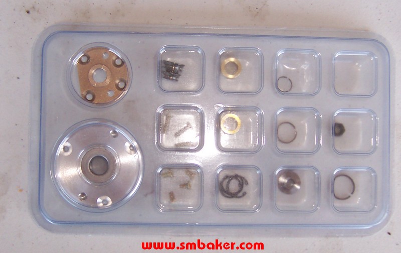
Note that your rebuild kit should include (2) replacement bearings, (3) replacement snap rings, (4) replacement thrust plate screws, (3) replacement seal plate screws, (1) replacement compressor nut, (1) replacement thrust bearing, and (1) replacement thrust spacer. You should also have a replacement piston ring for the turbine side of the shaft. Your kit will probably also include a replacement piston and (2) piston rings to go on it. The replacement piston and rings are not used if you’re installing a carbon seal.
To upgrade to a carbon seal, you’ll probably need to order a carbon seal and a thrust collar in addition to the standard rebuild kit. Here is what the carbon seal and the thrust collar look like:
Rebuilding:
- to be continued…
Hello,
I appreciate this article greatly as there is no longer any information on these turbochargers. However I was shocked when the rebuilding part was “to be continued…”
Do you still see yourself finishing this article? Please let me know at ryanx.klingler@gmail.com.